Universal Joint Analysis Using Ansys Workbench
OBJECTIVE
- To assign the structural steel, stainless steel, and titanium alloy material for the joint with the spring part, according to the case, and structural steel for the rest of the parts.
- To assign the joints.
- To mesh the model.
- To apply the boundary condition.
- To collect the results and interpret.
PROCEDURE
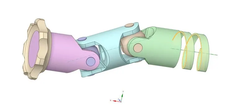
This simulation was an analysis of a double universal joint with spring. The universal joint model can be seen in the figure below. The simulation seems to be transient-structural, therefore, it had to solve using the transient-structural module of Ansys. The simulation was solved with three different cases. In the first case, the material of the joint with spring part was kept as structural steel, in the second it was stainless steel, and third, it was titanium alloy.
 |
|
Figure 1: Double universal joint with spring model in Ansys GUI. |
The Mesh section of the Transient Structural module was opened. In that, the material of all the parts was set to structural steel (default), for the first case, and set the material of the joint with spring to parametrical.
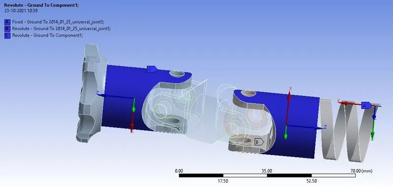
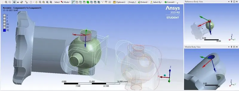
Further, the automatically detected contacts by Ansys were deleted, and several revolute joints were created as shown in the figure below.
A revolute joint was defined for the driving joint, the joint with spring, and all the other parts keeping the spider of the universal joint as reference.
 |
|
Figure 2: Fixed joint for the spring, the revolute joint for the joint with spring, and the driving joint. |
 |
|
Figure 3: Revolute joint for the universal joint, keeping the spider as reference. Similar joints were created for all the remaining 7 joints. |
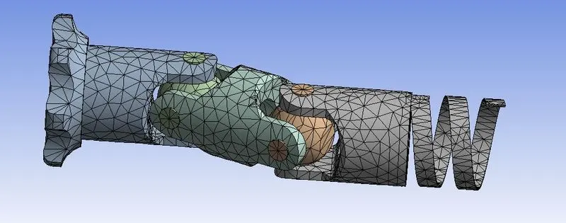
Next, the mesh was created for the model, as shown in the figure below.
 |
|
Figure 4: Meshing of the model. |
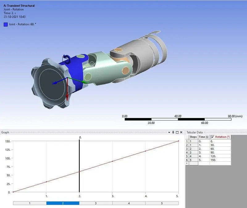
The analysis was solved in 5 steps. In boundary condition, the rotation was applied to the driving joint in 5 steps, as shown in the figure.
 |
|
Figure 5: Rotation applied to the driving joint. |
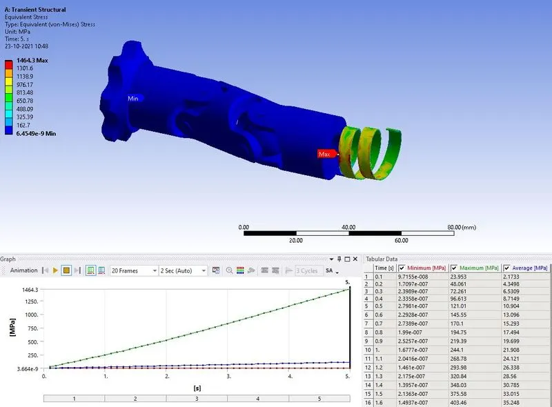
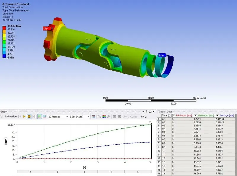
In the solution, the results were requested for the equivalent stress, total deformation, and set the maximum value of it to parametrical. All the results are shown in the figures below.
 |
|
Figure 6: Equivalent stress in the model, with maximum stress of 1464.3 MPa, on spring. |
 |
|
Figure 7: Total deformation in the model with maximum deformation of 38.637 mm, at wheel, and minimum at fixed joint. |
 |
|
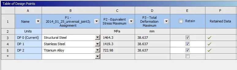
Figure 8: Results of all the cases. |
CONCLUSION
This simulation was performed to study the procedure of simulating the double universal joint model. In this model a spring was fixed at one end and was pressed through the double universal joint, using the handle. After pressing it, the stress increased in it was observed. It was found that the stress generation is more when the structural steel material was used, and the least when the titanium alloy material was used. The deformation remained the same.