Universal Joint
AIM:
- To perform transient structural analysis of Universal joint and evaluate the stress and deformation results.
OBJECTIVES OF THE PROJECT:
- To assign Structural steel, stainless steel and titanium alloy material for the Shaft A.
- To define the joints for the ball joint.
- To define Joint loads.
- To mesh the model.
- To evaluate the stress, deformation and strain in the work piece.
PROCEDURE:
- Case 1 – Structural steel
- OPEN WORKBENCH21 > NEW PROJECT > TRANSIENT STRUCTURAL.
- This will start a new transient structural project.
- Rename the project as Case1.
- Go to ENGINEERING DATA > STRUCTURAL STEEL.
- Then double click on Geometry. This will open the Spaceclaim.
- In Space claim check the model for any dents or irregularities.
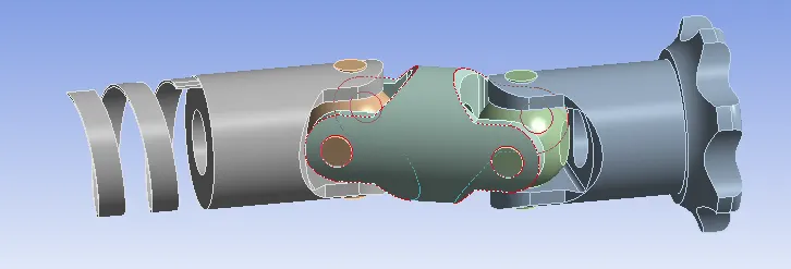
- The geometry looks good, exit the Spaceclaim.
- Then double click on Model. This will open Mechanical module.
- Now, rename the geometry as Shaft A, Shaft B, ball A, ball B and coupler.
- Then assign Structural steel to all the parts.
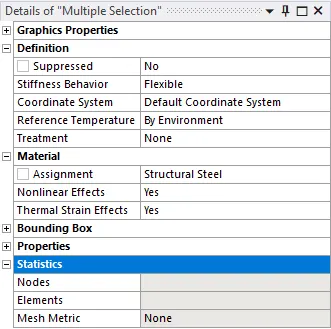
- Then go to CONTACTS > CONTACT > DELETE ALL CONTACTS.
- CONNECTIONS > INSERT > JOINT > TYPE = BODY-GROUND > TYPE = FIXED > SCOPE = SPRING END.
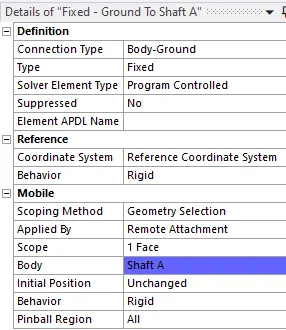
- CONNECTIONS > INSERT > JOINT > TYPE = BODY-GROUND > TYPE = REVOLUTE > SCOPE = SHAFT B.
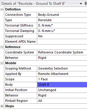
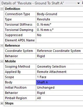
- CONNECTIONS > INSERT > JOINT > TYPE = BODY-GROUND > TYPE = REVOLUTE > SCOPE = SHAFT A.
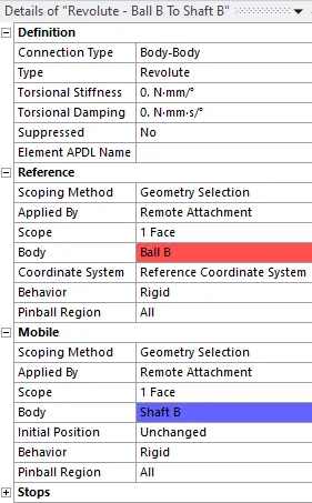
- CONNECTIONS > INSERT > JOINT > TYPE = BODY-BODY > TYPE = REVOLUTE > REFERENCE SCOPE = BALL B > MOBILE SCOPE = SHAFT B.
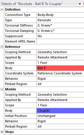
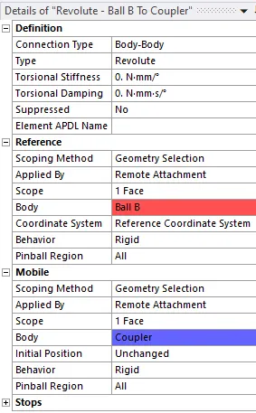
- CONNECTIONS > INSERT > JOINT > TYPE = BODY-BODY > TYPE = REVOLUTE > REFERENCE SCOPE = BALL B > MOBILE SCOPE = COUPLER.
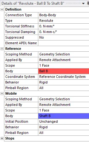
- CONNECTIONS > INSERT > JOINT > TYPE = BODY-BODY > TYPE = REVOLUTE > REFERENCE SCOPE = BALL B > MOBILE SCOPE = SHAFT B.
- CONNECTIONS > INSERT > JOINT > TYPE = BODY-BODY > TYPE = REVOLUTE > REFERENCE SCOPE = BALL B > MOBILE SCOPE = COUPLER.
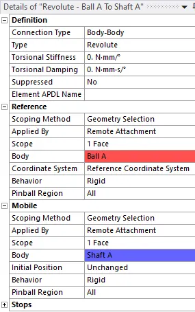
- CONNECTIONS > INSERT > JOINT > TYPE = BODY-BODY > TYPE = REVOLUTE > REFERENCE SCOPE = BALL A > MOBILE SCOPE = SHAFT A.
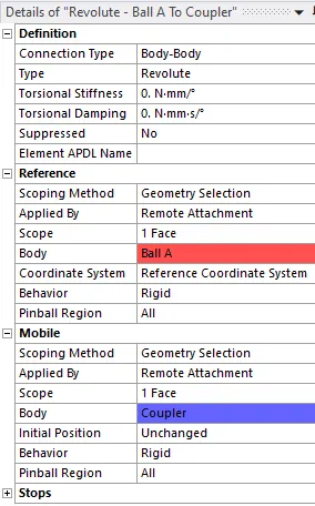
- CONNECTIONS > INSERT > JOINT > TYPE = BODY-BODY > TYPE = REVOLUTE > REFERENCE SCOPE = BALL A > MOBILE SCOPE = COUPLER.
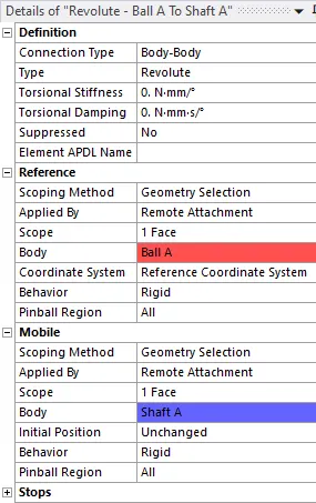
- CONNECTIONS > INSERT > JOINT > TYPE = BODY-BODY > TYPE = REVOLUTE > REFERENCE SCOPE = BALL A > MOBILE SCOPE = SHAFT A.
- CONNECTIONS > INSERT > JOINT > TYPE = BODY-BODY > TYPE = REVOLUTE > REFERENCE SCOPE = BALL A > MOBILE SCOPE = COUPLER.
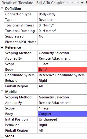
- This will define the Joint loads.
- Now, go to MESH > ELEMENT LENGTH = 4MM > GENERATE MESH.
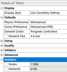
- The mesh will be generated on the model.
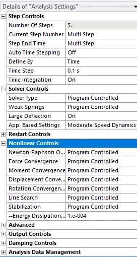
- Then go to STATIC STRUCTURAL > ANALYIS SETTINGS > NO OF STEPS = 5 > AUTO TIME STEPPING = OFF > TIME STEP = 0.1S > TIME INTEGRATION = ON > LARGE DEFLECTION = ON > WEAK SPRINGS = PROGRAM CONTROLLED > OUTPUT CONTROLS = YES.
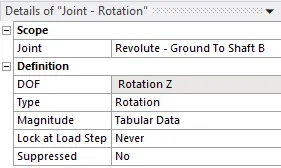
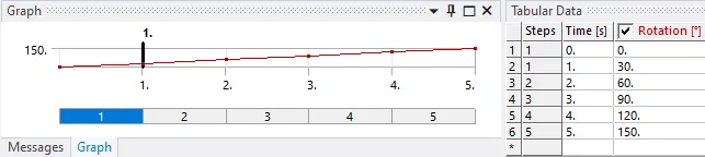
- Go to STATIC STRUCTURAL > INSERT > JOINT LOAD = REVOLUTE – GROUND TO SHAFT B > TYPE = ROTATION > MAGNITUDE = TABULAR DATA.
- Then, go to SOLUTION > INSERT > STRESS > STRAIN > DEFORMATION.
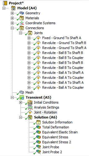
- This will set the output results.
- Then SOLUTION > SOLVE.
- Case 2 – Stainless Steel
- Create a duplicate project of the case 1 and rename it as case 2.
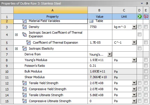
- Go to ENGINEERING DATA > STAINLESS STEEL > ADD.
- Then open Mechanical module.
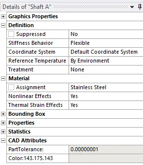
- Assign Stainless steel to shaft A.
- Go to SOLUTION and SOLVE.
- Case 3 – Titanium Alloy
- Create a duplicate project of the case 1 and rename it as case 3.
- Go to ENGINEERING DATA > TITANIUM ALLOY > ADD.
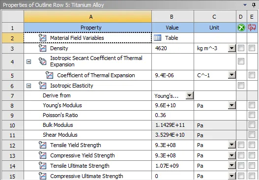
- Then open Mechanical module.
- Assign Titanium alloy to shaft A.
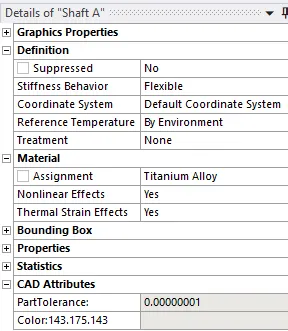
- Go to SOLUTION and SOLVE.
RESULTS:
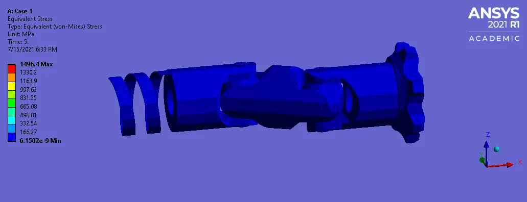
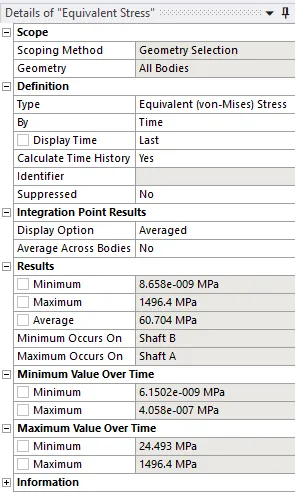
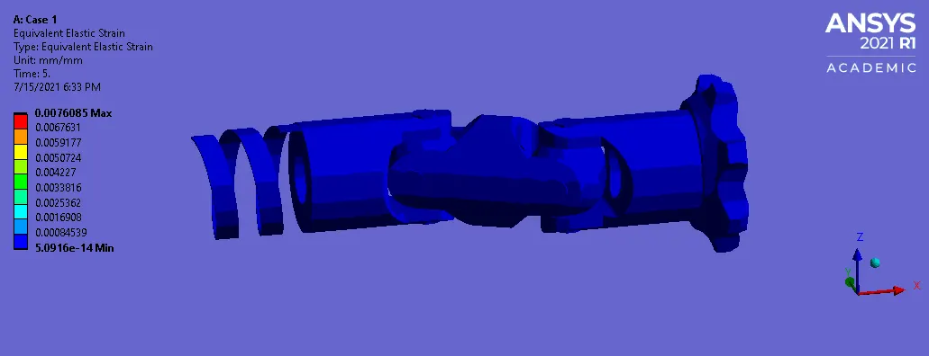
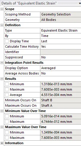
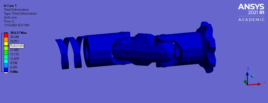
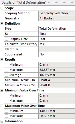
- Case 1 – Structural steel
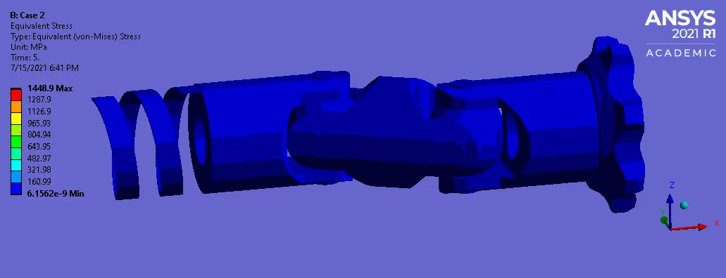
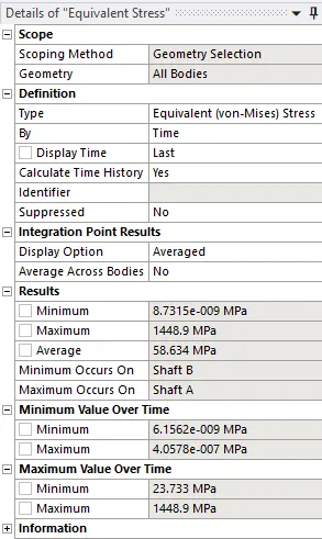
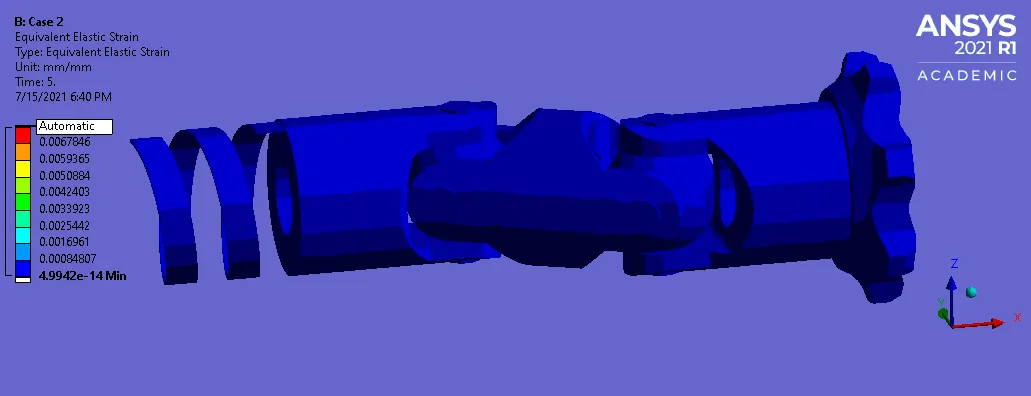
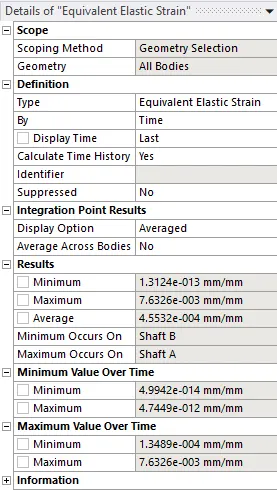
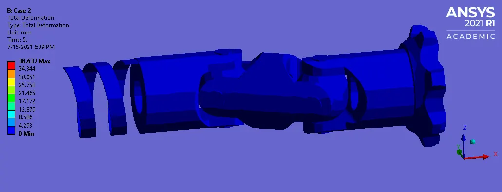
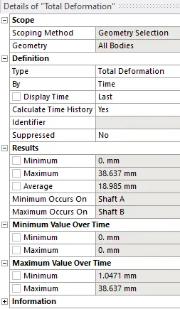
- Case 2 – Stainless Steel
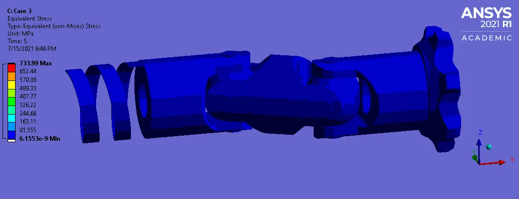
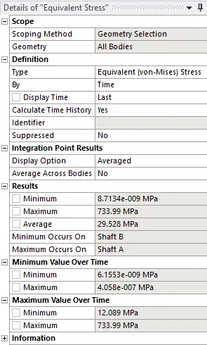
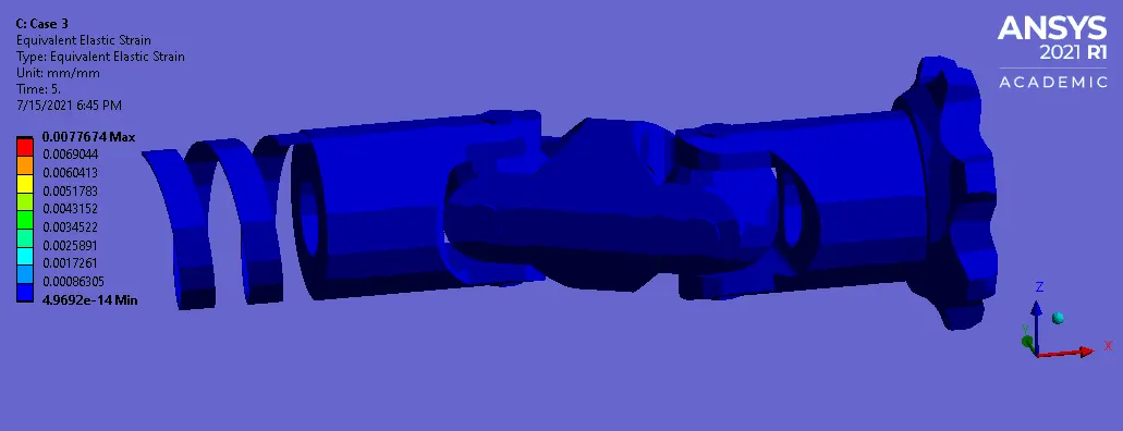
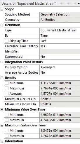
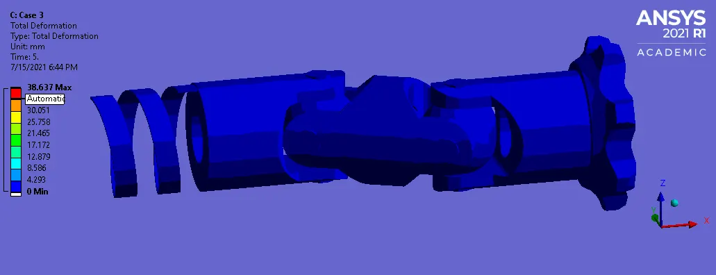
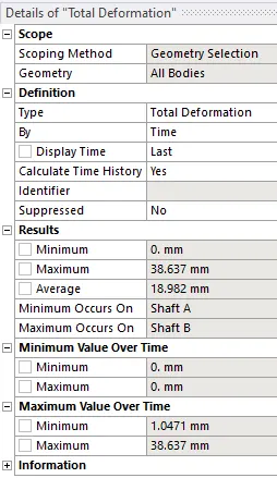
- Case 3 – Titanium Alloy
COMPARISON TABLE:
| Stress (MPa) | Strain | Deformation (mm) | |
| Structural Steel | 1496.4 | 7.6085E-3 | 38.637 |
| Stainless Steel | 1448.9 | 7.6326E-3 | 38.637 |
| Titanium Alloy | 733.99 | 7.7674E-3 | 38.637 |
- We can observe that, Structural steel produces more stress than Stainless steel and Titanium alloy.
- The variation in strain rate is observed to be less.
- The deformation remains constant.
LEARNING OUTCOMES:
- To setup transient structural analysis
- To assign material from the material library.
- To define joint loads.
- To define rotation for Shaft B.
- To deploy mesh on the geometry.
- To define output results.
CONCLUSION:
- By performing this project we conclude that the Transient analysis of Universal Joint is performed and the stress, strain and deformation results are obtained.
MODEL LINK:
https://drive.google.com/file/d/1KrWaemy_OsZ9lsNhyU3ESSw_lSUqbds_/view?usp=sharing