Week 8 - Universal Joint
SIMULATION OF DOUBLE UNIVERSAL JOINT WITH A SPRING
OBJECTIVE
To perform Transient Structural analysis on a Double Universal Joint with a spring using three different materials namely,
- Structural Steel
- Stainless Steel
- Titanium alloy
The above three materials must be assigned to the joint with springs alone
Compare the results of Equivalent stress and Total Deformation for all the three cases
MODEL SETUP
The 3D model of the setup is imported into ANSYS Space Claim. Check for any abnormalities in the Geometry.
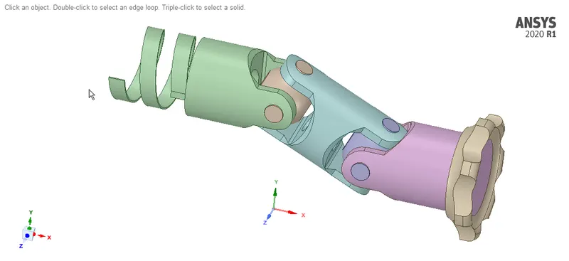
MATERIAL ASSINGMENT:
Structural Steel is assigned to the components, but the materials assigned to the joint with springs are changed for three different cases. They are,
Case 1: Structural Steel
Case 2: Stainless Steel
Case 3: Titanium alloy
The properties of various materials used are shown below
- Structural Steel :
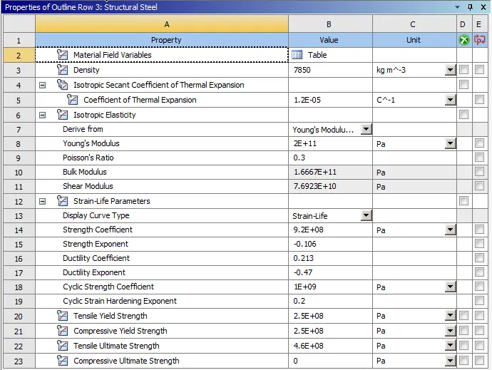
- Stainless Steel :
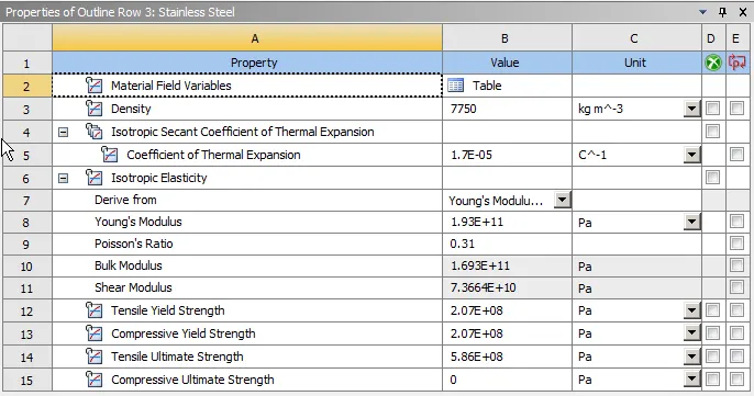
- Titanium alloy:
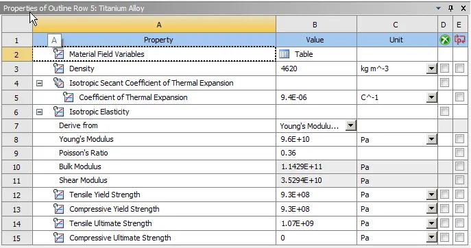
MODEL SETUP:
After importing the Geometry, rename the Parts and assign respective materials.
JOINT DEFINITION:
We need to define joints for the model, they are
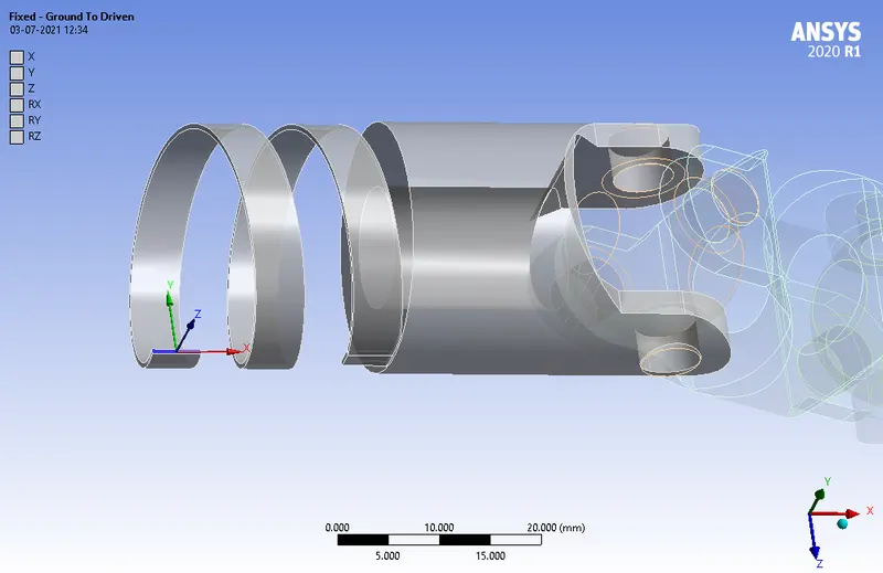
- A Fixed Support at the end face of the Spring:
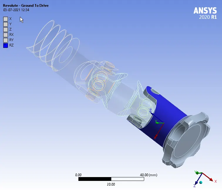
- A Revolute joint is assigned to the Drive :
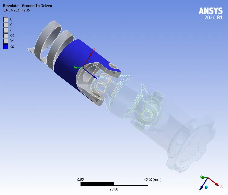
- A Revolute joint is assigned to the Driven :
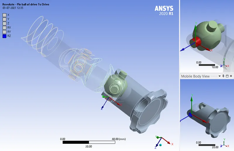
- Two Body-Body Revolute joints is assigned between the Pin ball of Drive and the Drive:
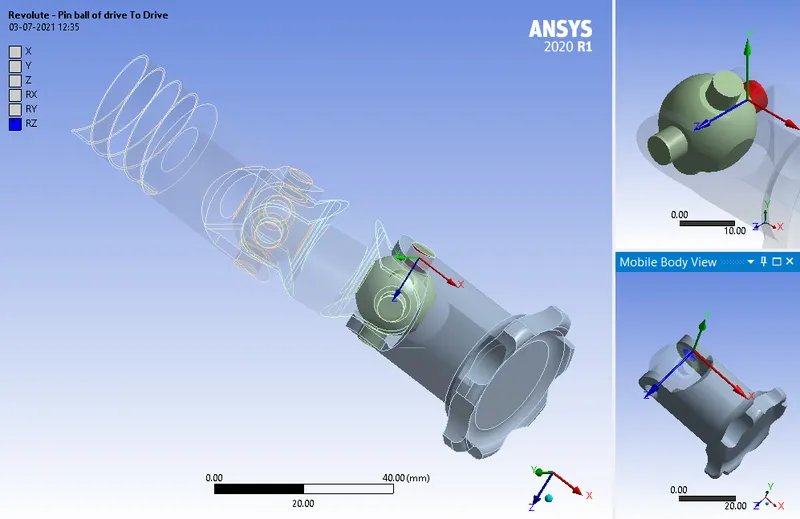
- Two Body-Body Revolute joints is assigned between the Pin ball of Drive and the Coupler:
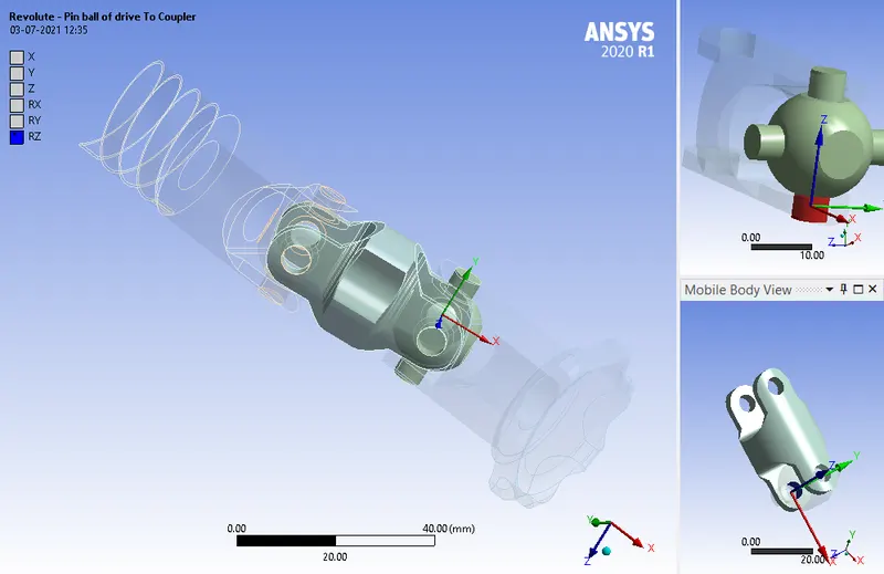
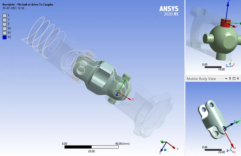
- Two Body-Body Revolute joints is assigned between the Pin ball of Driven and the Driven:
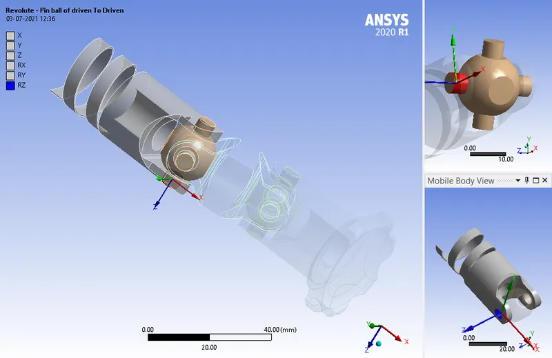
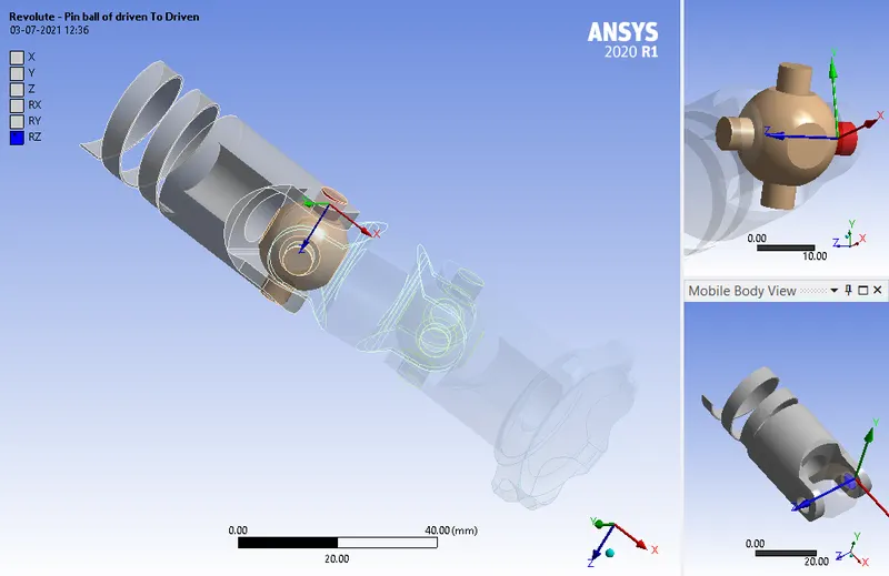
- Two Body-Body Revolute joints is assigned between the Pin ball of Driven and the Coupler:
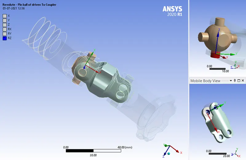
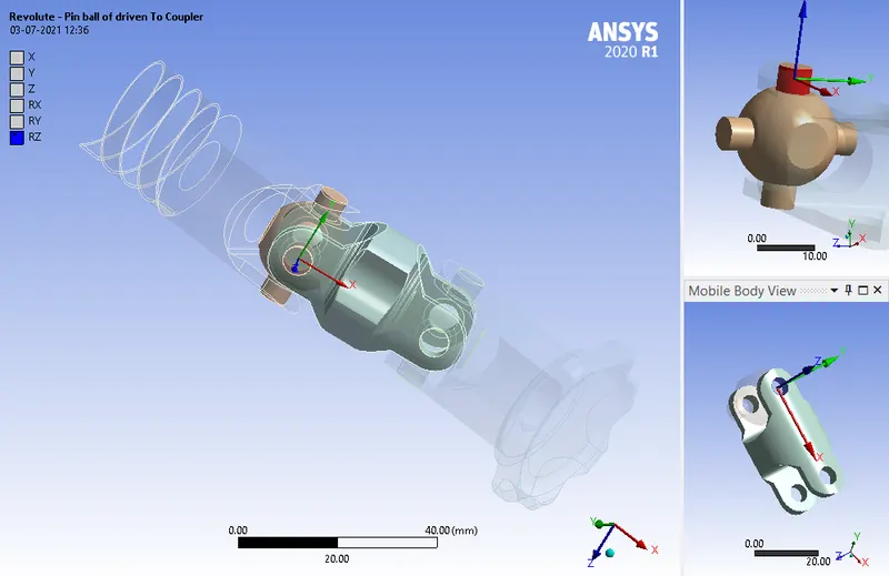
Also make sure the reference co-ordinate system assigned to the joints are same as shown above.
MESHING:
The meshing is done as follows,
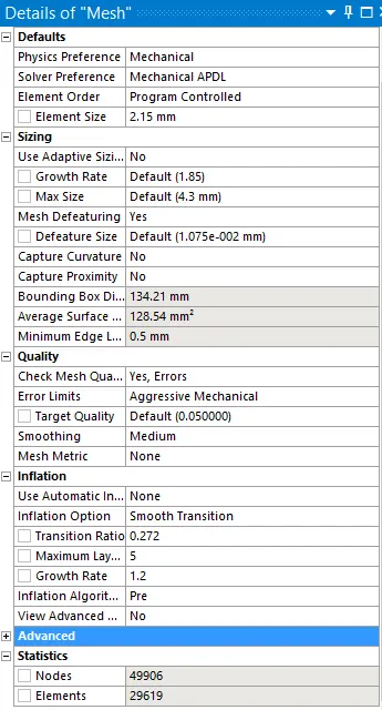
- A element size of 2.15 mm is assigned to all the components.
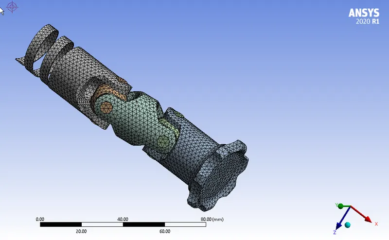
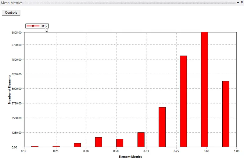
The details and settings of the mesh are shown below.
MESH QUALITY:
ANALYSIS SETTINGS:
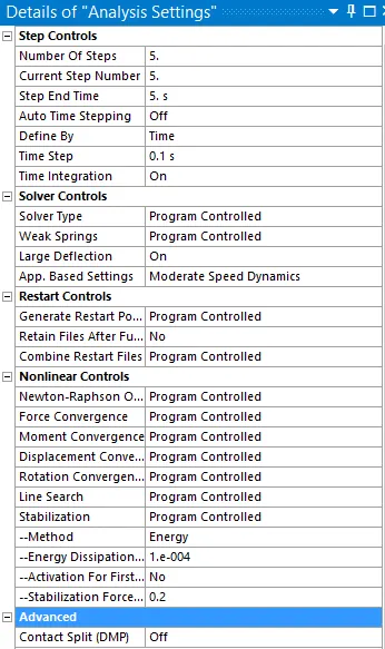
Now, the simulation is run for 5 steps. The following settings are modified
Auto Time stepping is set to OFF and Time step values are assigned as shown below.
Solver Type is set to Program Controlled
Weak springs are set to Program Controlled
The Large deflection is set to ON.
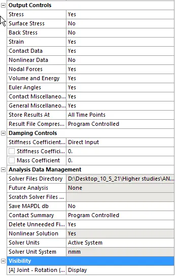
Other settings are as shown below
BOUNDARY CONDITIONS:
The boundary condition for this model are
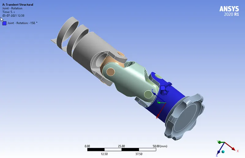
- A Rotational Joint load is assigned to the Drive :
RESULTS:
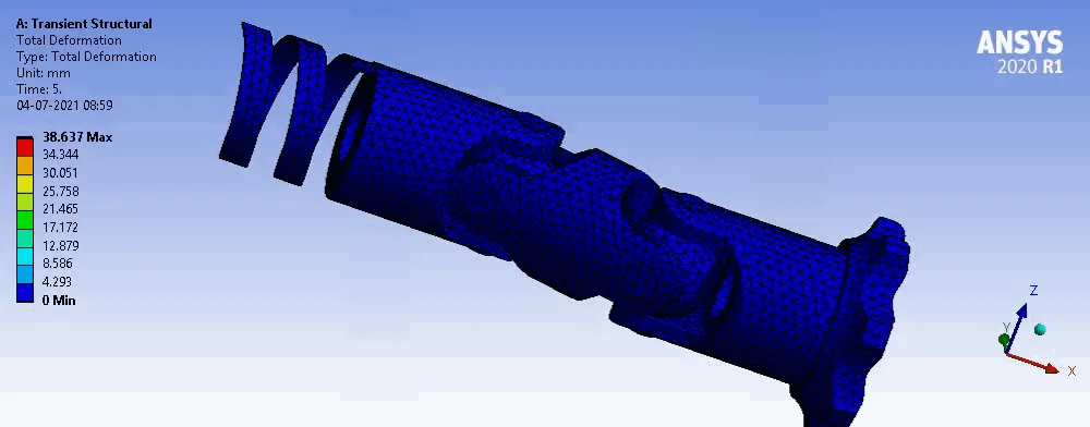
ANIMATION:
CASE 1:
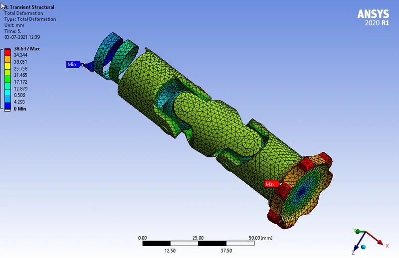
- Total deformation
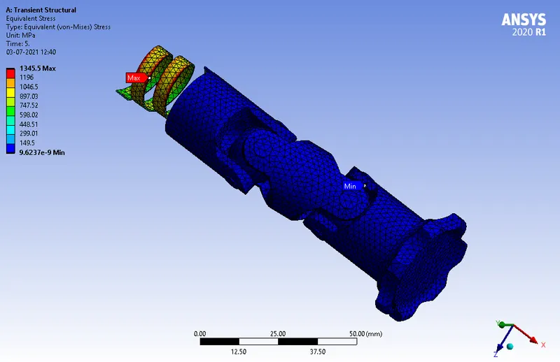
- Equivalent stress
CASE 2:
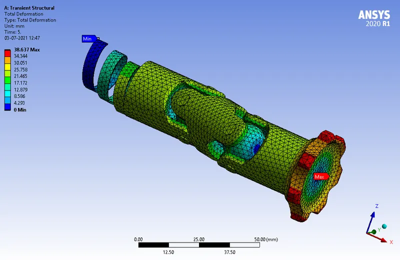
- Total deformation
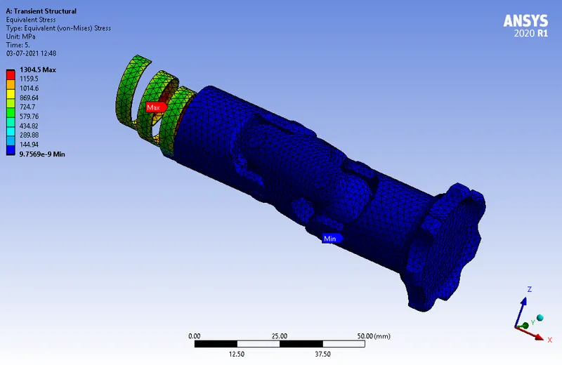
- Equivalent stress
CASE 3:
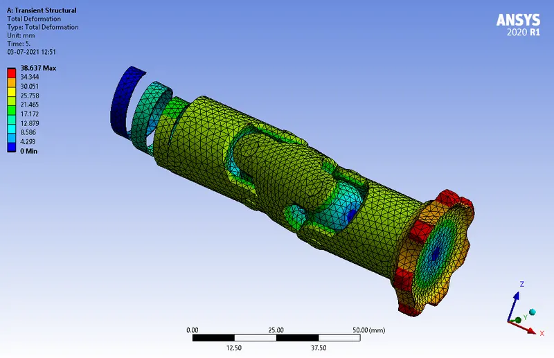
- Total deformation
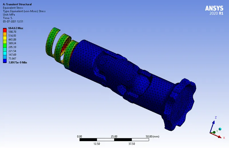
- Equivalent stress
CONCLUSION:
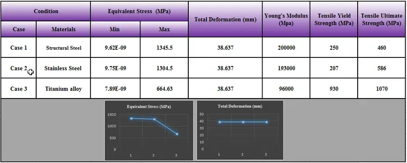
From the results, it can be inferred that
- Equivalent Stress remains almost same for both Case 1 (Structural Steel) and Case 2 (Stainless Steel), but decreases to almost half of the value in Case 3 (Titanium Alloy)
- Total Deformation remains the same for all the three cases
- For same Deformation, Equivalent Stress induced is greater than both Tensile Yield Strength and Ultimate Strength in Case 1 and Case 2, but for Titanium Alloy, Stress induced is less than the Tensile Yield Strength and well below the Ultimate Tensile Strength. So it is recommended to use Titanium Alloy as the material for the Joint with Spring
The simulation files are attached below