Week 4- Rolling operation
STATIC STRUCTURAL ANALYSIS ON ROLLING OPERATION
OBJECTIVE
To perform static structural analysis on the Rolling operation of Copper.
The simulation have to be carried out in 14 steps with random values for displacement and displace the workpiece by 90mm.
Finally compute the following results,
- Equivalent stress for the whole setup
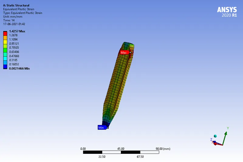
- Equivalent Plastic strain for the workpiece
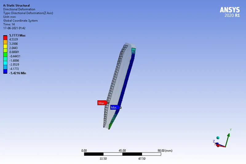
- Directional Deformation in the Z axis for the workpiece
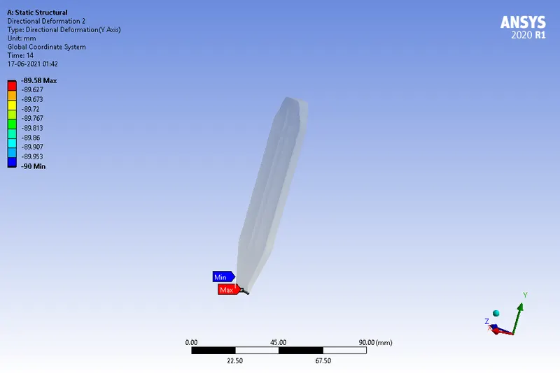
- Prove that the workpiece has displaced by 90mm.
MODEL SETUP
The 3D model of the setup is imported into ANSYS Space Claim. Check for any abnormalities in the Geometry. The dimension of the workpiece is (100*9*10) mm.
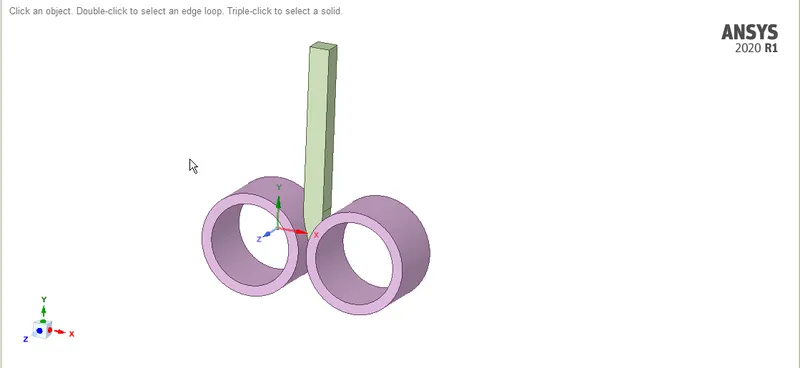
MATERIAL ASSINGMENT:
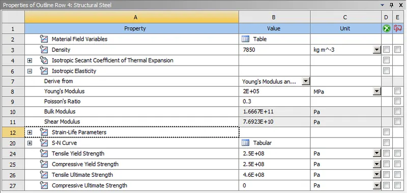
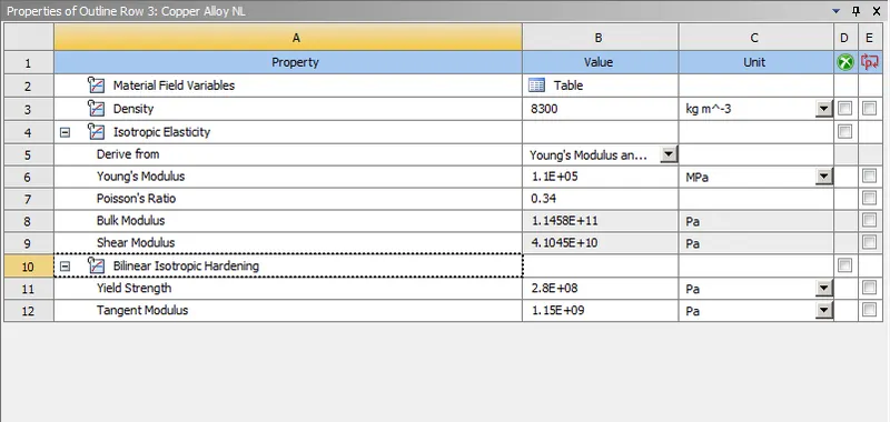
The properties of various materials used are shown below
- Structural Steel:
- Copper Alloy NL:
CONTACTS DEFINITION:
We need to define 2 contact regions for this model.
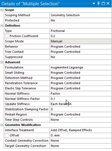
Frictional contact with a coefficient of friction as 0.2 is selected between the
- External surface of Wheel 1 and one face of the workpiece which is in contact with wheel 1
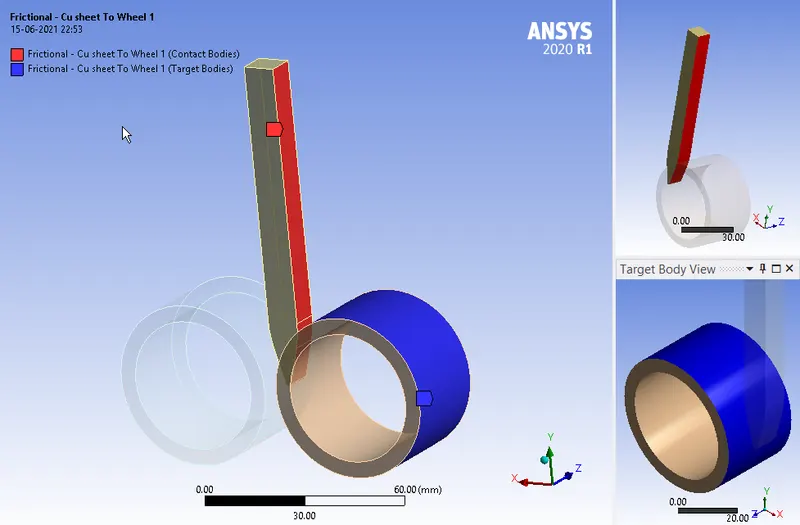
- External surface of Wheel 2 and other face of the workpiece which is in contact with wheel 2
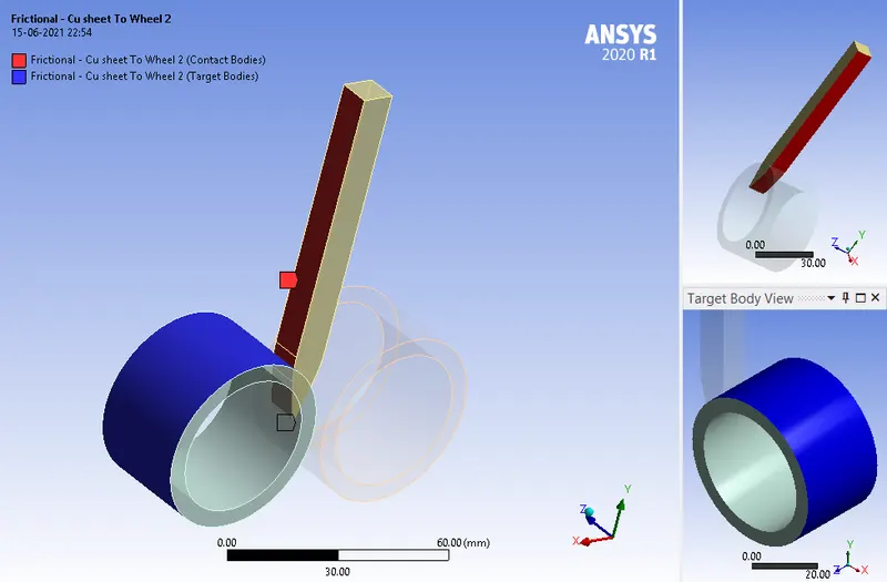
The settings are shown as below
MESHING:
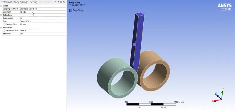
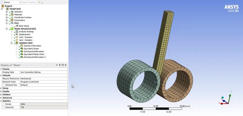
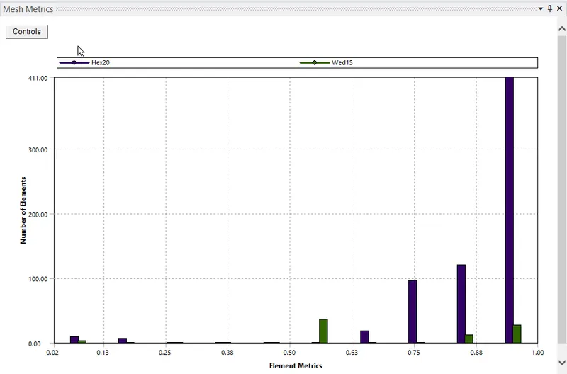
The workpiece has been meshed for a element size of 3mm and all other parts are of default mesh
JOINT DEFINITION:
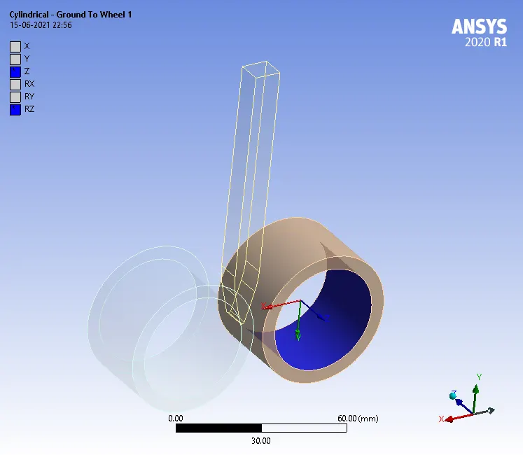
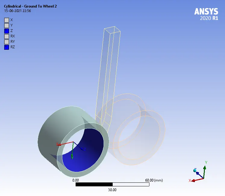
We need to define two joints for this rolling operation. They are
- A Cylindrical joint for wheel 1
- A cylindrical joint for wheel 2
ANALYSIS SETTINGS:
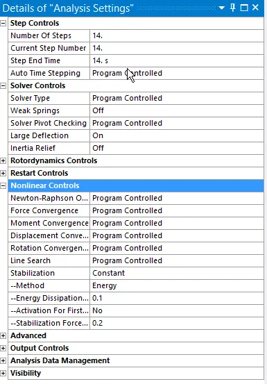
Now, the simulation is run for 14 step. Auto Time stepping is set to Program Controlled. The Large deflection is set to ON. Other settings are as shown below
BOUNDARY CONDITIONS:
The boundary condition for this model are
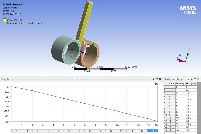
- A Displacement of 90mm in the Y direction:
For this, the sides of the workpiece which doesn’t contact the rollers have to be selected to avoid slipping.
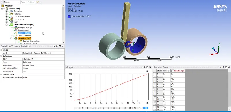
- A revolute joint load for wheel 1
The angles of rotation are tabulated as shown
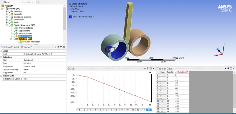
- A revolute joint load for wheel 2
The angles of rotation are tabulated as shown
RESULTS:
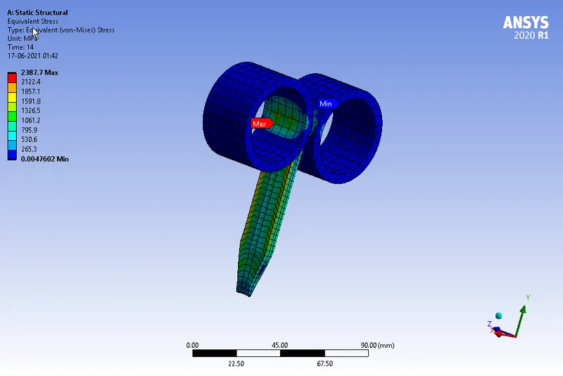
- Equivalent Stress for the whole setup:
- Equivalent Plastic Strain of the workpiece:
- Directional Deformation in the Z axis for the workpiece:
- Displacement of workpiece by 90mm:
CONCLUSION:
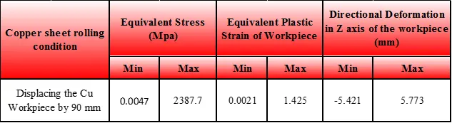
- From the above results, it can be inferred that the workpiece thickness is increased to approximately 5.5mm on both sides.
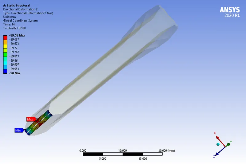
- From the above diagram, it can be proved that the workpiece have been displaced by 90 mm in the Y direction. Here the displacement is calculated from the movement of the selected two surfaces of the tip of workpiece in the Y direction. So the tip of the Workpiece travels 90mm.
The simulation files are attached below