Week 8 - Simulation of a backward facing step in OpenFOAM
Backward Facing Step:
- It is a representative model for separation flows, which find wide application in aerodynamic flows.
- The flow separation occurring due to sudden expansion geometry introduces various important features such as flow recirculation and re-attachment as shown in fig.
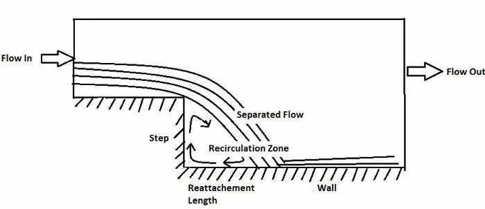
- In the current challenge simulation of incompressible laminar viscous flow using OpenFoam is presented.
- for this icoFoam solver in open foam is used. icoFoam solves the incompressible laminar Navier-stokes equation which is suitable for the problem.
Steps followed:
- In order to solve the problem tutorial on incompressible/icofoam/cavity is selected. In order to set up geometry and mesh the blockMesh file is used.
- BlockMeshDict:
- In this section, we edit the geometry of the problem and use blockMesh to create meshes with grading and curved edges.
- the file is located in the systems folder.
- The first 7 lines of the file give header information about OpenFoam and the version
- In the FoamFile section, the file information is provided.
- the scale shows the conversion factor to scale units of the geometry in meters. in our case, it is kept 1 as the geometry dimensions are already in meters.
- The principle of blockMesh is to divide the geometry into a set of 1 or more 3D hexahedral blocks. mesh is specified by the number of cells in each direction of the block.
- first, we define all the 21 vertices of the geometric of the given geometry in their respective x,y,z coordinates with 0 as the origin.
- The given geometry is defined as a collection of 5 blocks as shown in the figure below:
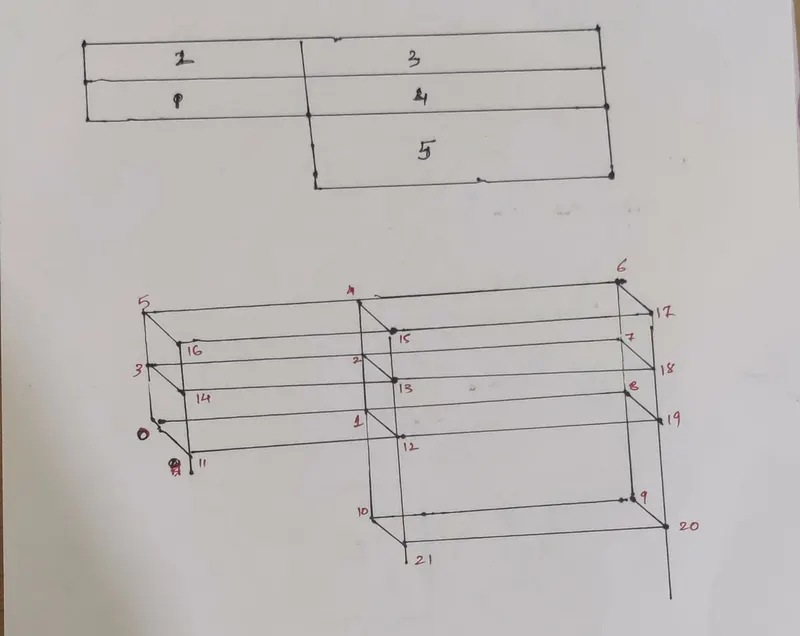
- The next step is to define these blocks in the format : hex (0 1 2 3 11 12 13 14) (80 10 1) simpleGrading (1 1 1)
- the hex(define 8 vertices that constitutes the block) (number of cells in each direction for the block) simpleGrading(1 1 1 - indicates that the sizes of all the cells are the same).
- this process is followed for all five blocks
- The next step is to define boundaries. A boundary is broken up into a set of patches. i.e the walls and faces like inlet, outlets upper and lower walls, and front and back walls
- we can see different types in each case the patch is a basic patch type and does not contain any information about the mesh ( exception wall)
- wall type is defined to store the distance from the wall, of the cell centers next to the wall as part of the patch.
- the empty type is defined to solve a 3D geometry problem in 1 or 2 dimensions. this is defined on each patch whose plane is normal to the 3rd ( and 2nd ) dimension for which no solution is required.
/*--------------------------------*- C++ -*----------------------------------*\
  =========                 |
  \\      /  F ield         | OpenFOAM: The Open Source CFD Toolbox
   \\    /   O peration     | Website:  https://openfoam.org
    \\  /    A nd           | Version:  8
     \\/     M anipulation  |
\*---------------------------------------------------------------------------*/
FoamFile
{
    version     2.0;
    format      ascii;
    class       dictionary;
    object      blockMeshDict;
}
// * * * * * * * * * * * * * * * * * * * * * * * * * * * * * * * * * * * * * //

convertToMeters 1;

vertices
(
    (0 0 0)
    (0.08 0 0)
    (0.08 0.005 0)
    (0 0.005 0)
    (0.08 0.01 0)
    (0 0.01 0)
    (0.2 0.01 0)
    (0.2 0.005 0)
    (0.2 0 0)
    (0.2 -0.01 0)
    (0.08 -0.01 0)
    (0 0 0.1)
    (0.08 0 0.1)
    (0.08 0.005 0.1)
    (0 0.005 0.1)
    (0.08 0.01 0.1)
    (0 0.01 0.1)
    (0.2 0.01 0.1)
    (0.2 0.005 0.1)
    (0.2 0 0.1)
    (0.2 -0.01 0.1)
    (0.08 -0.01 0.1)
);

blocks
(
    hex (0 1 2 3 11 12 13 14) (80 10 1) simpleGrading (1 1 1)
    hex (3 2 4 5 14 13 15 16) (80 10 1) simpleGrading (1 1 1)
    hex (2 7 6 4 13 18 17 15) (120 10 1) simpleGrading (1 1 1)
    hex (1 8 7 2 12 19 18 13) (120 10 1) simpleGrading (1 1 1)
    hex (10 9 8 1 21 20 19 12) (120 10 1) simpleGrading (1 1 1)
);

edges
(
);

boundary
(
    Inlet
    {
        type patch;
        faces
        (
            (0 11 14 3)
            (3 14 16 5)
        );
    }
    Outlet
    {
        type patch;
        faces
        (
            (9 8 19 20)
            (8 7 18 19)
            (7 6 17 18)
        );
    }
    frontAndBack
    {
        type empty;
        faces
        (
            (0 1 2 3)
            (3 2 4 5)
            (2 7 6 4)
            (1 8 7 2)
            (10 9 8 1)
            (11 12 13 14)
            (14 13 15 16)
            (13 18 17 15)
            (12 19 18 13)
            (21 20 19 12)
        );
    }
    fixedWalls
    {
    	type wall;
    	faces
    	(
    	     (6 4 15 17)
    	     (4 5 16 15)
    	     (10 21 12 1)
    	     (1 0 11 12)
    	     (9 10 21 20)
    	);
    }
);

mergePatchPairs
(
);

// ************************************************************************* //- ControlDict
- In OpenFOAM solvers begin all runs by setting up a database. controlDict dictionary sets parameters important for creating this database.
- In this we set the start-time to 0, end time to 10sec, time step DeltaT to 0.001 ( this should be selected such that the CFL number is less than 1, otherwise it will lead to stability and accuracy issues).
- writeControl controls the timing of writing the output to file. The writeInterval 100 i.e. time data should be written for every 100-time steps interval.
/*--------------------------------*- C++ -*----------------------------------*\
  =========                 |
  \\      /  F ield         | OpenFOAM: The Open Source CFD Toolbox
   \\    /   O peration     | Website:  https://openfoam.org
    \\  /    A nd           | Version:  8
     \\/     M anipulation  |
\*---------------------------------------------------------------------------*/
FoamFile
{
    version     2.0;
    format      ascii;
    class       dictionary;
    location    "system";
    object      controlDict;
}
// * * * * * * * * * * * * * * * * * * * * * * * * * * * * * * * * * * * * * //

application     icoFoam;

startFrom       startTime;

startTime       0;

stopAt          endTime;

endTime         10;

deltaT          0.001;

writeControl    timeStep;

writeInterval   100;

purgeWrite      0;

writeFormat     ascii;

writePrecision  6;

writeCompression off;

timeFormat      general;

timePrecision   6;

runTimeModifiable true;


// ************************************************************************* //- transportProperties
- The file is located in the constant folder of the case.
- here we set the viscosity to 1e-5 i.e. f
/*--------------------------------*- C++ -*----------------------------------*\
  =========                 |
  \\      /  F ield         | OpenFOAM: The Open Source CFD Toolbox
   \\    /   O peration     | Website:  https://openfoam.org
    \\  /    A nd           | Version:  8
     \\/     M anipulation  |
\*---------------------------------------------------------------------------*/
FoamFile
{
    version     2.0;
    format      ascii;
    class       dictionary;
    location    "constant";
    object      transportProperties;
}
// * * * * * * * * * * * * * * * * * * * * * * * * * * * * * * * * * * * * * //

nu              [0 2 -1 0 0 0 0] 1e-5;


// ************************************************************************* //- Initial conditions:
- the initial conditions for the problem can be set up from the 0 folder in the case where the 0 folder indicates the conditions at time = 0 sec (start time).
- it is important to define the boundaries as we have defined in the blockMeshDict.
- here we change the velocity at the inlet to 0.02 sec.
- the zeroGradient condition is specified at the outlet to indicate that the velocity is fully developed at the outlet.
- the empty condition reduces the 3D geometries to 1D or 2D. it is applied to the front and back as no solution is required in the direction normal to them.
- the noSlip condition is specified at the top and bottom fixed walls.
- the initial conditions for the problem can be set up from the 0 folder in the case where the 0 folder indicates the conditions at time = 0 sec (start time).
/*--------------------------------*- C++ -*----------------------------------*\
  =========                 |
  \\      /  F ield         | OpenFOAM: The Open Source CFD Toolbox
   \\    /   O peration     | Website:  https://openfoam.org
    \\  /    A nd           | Version:  8
     \\/     M anipulation  |
\*---------------------------------------------------------------------------*/
FoamFile
{
    version     2.0;
    format      ascii;
    class       volVectorField;
    object      U;
}
// * * * * * * * * * * * * * * * * * * * * * * * * * * * * * * * * * * * * * //

dimensions      [0 1 -1 0 0 0 0];

internalField   uniform (0 0 0);

boundaryField
{
    Inlet
    {
        type            fixedValue;
        value           uniform (0.02 0 0);
    }

    Outlet
    {
    	type		zeroGradient
    }

    frontAndBack
    {
        type            empty;
    }

    fixedWalls
    {
        type            noSlip;
    }
}

// ************************************************************************* //- p:
- similar to U the initial condition of pressure is changed.
- the inlet is specified to zerogradient.
- outlet to a fixed value of 0.
- the fixed walls are given zeroGradient boundary condition which means the normal gradient of pressure is zero.
- the front and back case are set to empty as it is a 2D case.
/*--------------------------------*- C++ -*----------------------------------*\
  =========                 |
  \\      /  F ield         | OpenFOAM: The Open Source CFD Toolbox
   \\    /   O peration     | Website:  https://openfoam.org
    \\  /    A nd           | Version:  8
     \\/     M anipulation  |
\*---------------------------------------------------------------------------*/
FoamFile
{
    version     2.0;
    format      ascii;
    class       volScalarField;
    object      p;
}
// * * * * * * * * * * * * * * * * * * * * * * * * * * * * * * * * * * * * * //

dimensions      [0 2 -2 0 0 0 0];

internalField   uniform 0;

boundaryField
{
    Inlet
    {
        type            zeroGradient;
    }

    Outlet
    {
        type            fixedValue;
        value		 uniform 0;
    }

    fixedWalls
    {
        type            zeroGradient;
    }

    frontAndBack
    {
        type            empty;
    }
}

// ************************************************************************* //
Results:
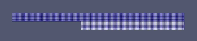
- we can see from the mesh of case 1 shown in fig 1 that all the cell sizes are equal thus indicating no mesh grading incorporated in this case.
- Velocity Magnitude plot:
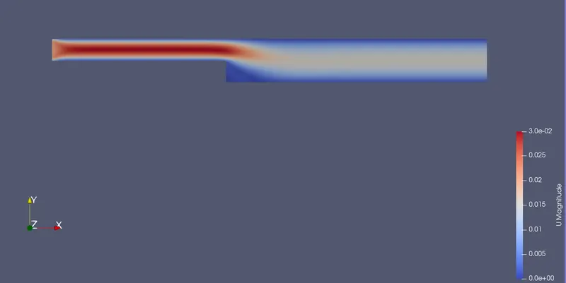
- The velocity magnitude plot is shown in the figure.2 minor recirculation is observed near the backward step.
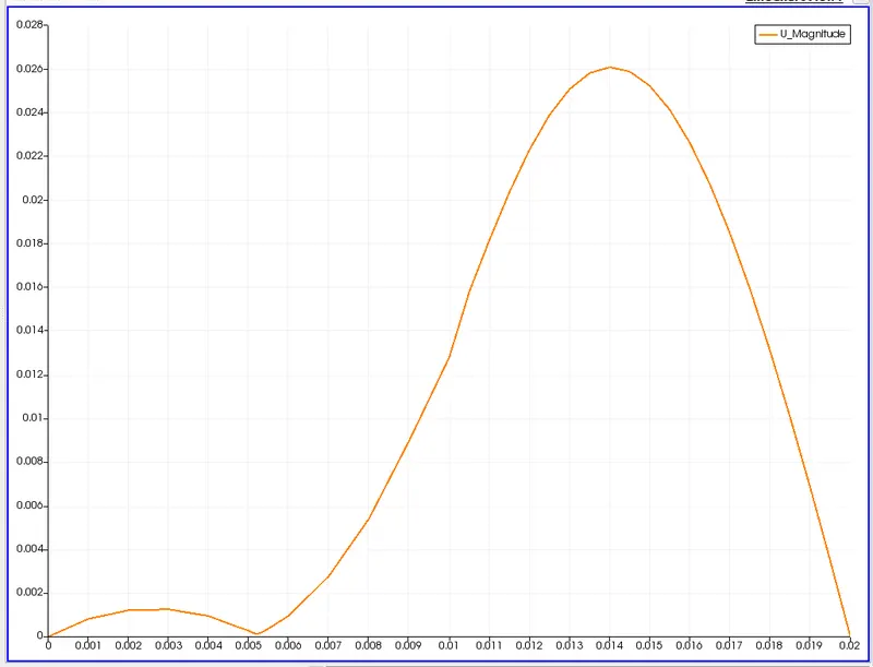
- The plot shown in figure 3 shows the velocity distribution at a distance of 0.085 m from the inlet.
Mesh Grading:
- the error in the numerical solution is more in the regions where the nature of the true solution deviates from that assumed in the numerical scheme ( eg. if a numerical scheme assumes linear variation of variables over cells and the error is largest in the regions where true solution deviates greatest from the linear form). this error decreases with cell size.
- So the mesh should be made finer in such regions and for that mesh, grading can be used.
- This can be done by changing the values of the simplegrading. these values indicate a ratio of `("last cell")/("first cell")`. the significance is given below:
-
L/F =1 all cells are of equal size L/F >1 starting cells are finner L/F <1 ending cells are finer
-
- For the current problem the regions where mesh grading is desired are as shown below:
- Also, we need to be careful while grading as it could also affect the CFL number as the dx value decreases.
- another important consideration is that neighboring blocks should have grading such that connectivity is maintained. for eg. in the case of blocks 1 and 4, there is no need for y grading in the block for but it should be the same as block 1 so that the mesh lines connect.
/*--------------------------------*- C++ -*----------------------------------*\
  =========                 |
  \\      /  F ield         | OpenFOAM: The Open Source CFD Toolbox
   \\    /   O peration     | Website:  https://openfoam.org
    \\  /    A nd           | Version:  8
     \\/     M anipulation  |
\*---------------------------------------------------------------------------*/
FoamFile
{
    version     2.0;
    format      ascii;
    class       dictionary;
    object      blockMeshDict;
}
// * * * * * * * * * * * * * * * * * * * * * * * * * * * * * * * * * * * * * //

convertToMeters 1;

vertices
(
    (0 0 0)
    (0.08 0 0)
    (0.08 0.005 0)
    (0 0.005 0)
    (0.08 0.01 0)
    (0 0.01 0)
    (0.2 0.01 0)
    (0.2 0.005 0)
    (0.2 0 0)
    (0.2 -0.01 0)
    (0.08 -0.01 0)
    (0 0 0.1)
    (0.08 0 0.1)
    (0.08 0.005 0.1)
    (0 0.005 0.1)
    (0.08 0.01 0.1)
    (0 0.01 0.1)
    (0.2 0.01 0.1)
    (0.2 0.005 0.1)
    (0.2 0 0.1)
    (0.2 -0.01 0.1)
    (0.08 -0.01 0.1)
);

blocks
(
    hex (0 1 2 3 11 12 13 14) (80 10 1) simpleGrading (0.2 5 1)
    hex (3 2 4 5 14 13 15 16) (80 10 1) simpleGrading (0.2 0.2 1)
    hex (2 7 6 4 13 18 17 15) (120 10 1) simpleGrading (5 0.2 1)
    hex (1 8 7 2 12 19 18 13) (120 10 1) simpleGrading (5 5 1)
    hex (10 9 8 1 21 20 19 12) (120 10 1) simpleGrading (5 5 1)
);

edges
(
);

boundary
(
    Inlet
    {
        type patch;
        faces
        (
            (0 11 14 3)
            (3 14 16 5)
        );
    }
    Outlet
    {
        type patch;
        faces
        (
            (9 8 19 20)
            (8 7 18 19)
            (7 6 17 18)
        );
    }
    frontAndBack
    {
        type empty;
        faces
        (
            (0 1 2 3)
            (3 2 4 5)
            (2 7 6 4)
            (1 8 7 2)
            (10 9 8 1)
            (11 12 13 14)
            (14 13 15 16)
            (13 18 17 15)
            (12 19 18 13)
            (21 20 19 12)
        );
    }
    fixedWalls
    {
    	type wall;
    	faces
    	(
    	     (6 4 15 17)
    	     (4 5 16 15)
    	     (10 21 12 1)
    	     (1 0 11 12)
    	     (9 10 21 20)
    	);
    }
);

mergePatchPairs
(
);

// ************************************************************************* //- for this case, all the other files will be exactly the same as in case 1.
Results:
- In this case, the mesh grading is very clearly observed in fig.1 indicating finer mesh near the walls and region of step.
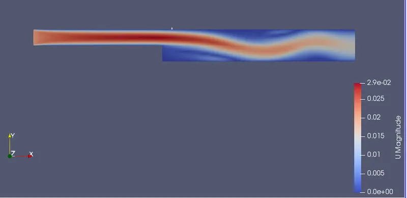
- In figure 2 represents the velocity magnitude plot, as compared to case 1 the recirculation regions are very prominent in this case.
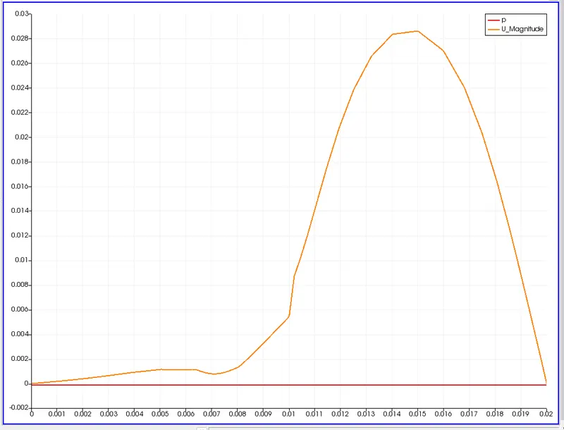
- figure 3 represents the velocity profile at a distance of 0.085m from the inlet. The results are better as compared to case 1.

Conclusion :
- We can conclude that the mesh grading generates more accurate results.
- The recirculation region is better captured when mesh grading is incorporated.
- Thus Mesh Grading reduces the error as the cells are finner in the regions where the true solution deviates from the assumed behavior.
- CFL number is sensitive to the mesh grading and thus it one should be careful while implementing it.