Week 8 - Simulation of a backward facing step in OpenFOAM
Aim of this project to create the geometry of back ward facing step with blockmesh and to simulate with an incompressible-laminar-viscous flow in the backward facing step
Description:-
First of all we need to find the correct tutorial in openfoam for our described physics then after we can change the necessary changes for the simulation we need to run.
The tutorial we need is in the Incompressible/laminar/cavity folder we'll make a copy of this folder into the $FOAM_RUN folder. then we will have copy of the tutorial so we can our own changes to this folder
in the cavity folder we'll have
- 0
- constant
- system
-0 folder will have initial conditions of our simulation for 0 time step
-constant folder holds the constant properties for our selected physics like transport properties, mesh etc..,
- system folder holds the our geometry, solvers
Navigate through the system folder and edit blockMeshDict file.
Creating the Geometry:-
Here we can create the geometry in terms of hexagonal blocks, a block must contain 8 vertices this should be kept in mind.!
I created my geometry by using 3 blocks and 15 vertices Every vertex has (x, y, z) co-ordinate length Here it is two dimensional.
The top of the file contains some dictionary file key values to run the C++ program.
then we'll have scaling factor followed by our vertices and blocks function.
In blocks function we'll define our 3 blocks with vertices and also by no of cells in x,y,z direction here (100, 20, 1) In z-direction we'll have one block becoz it is a two dimensional.
case :1 - In first we'll define by grading factor of 1
Grading factor is the ratio between length of end cell to first cell.
case:2 In second case we'll introduce the grading factor of 0.2 near the walls to observe the boundary layer phenomenon.
Multigrading option can be used to grade single block at both sides. The syntax as follows
simpleGrading
(
1 // x-direction expansion ratio
(
(0.2 0.3 4) // 20% y-dir, 30% cells, expansion = 4
(0.6 0.4 1) // 60% y-dir, 40% cells, expansion = 1
(0.2 0.3 0.25) // 20% y-dir, 30% cells, expansion = 0.25 (1/4)
)
1 // z-direction expansion ratio
)
For G.F = 0.2
simpleGrading (0.2 ((0.3 0.3 5) (0.4 0.4 1) (0.3 0.3 0.2)) 1 )
simpleGrading (5 ((0.3 0.3 5) (0.4 0.4 1) (0.3 0.3 0.2)) 1)
simpleGrading (5 5 1)
Boundary:-
Then we'll define our inlet,outlet of type patch , front and back face of type empty and Noslip wall of type wall by defining the faces of the geometry.
the order of the vertices should be in a way that the normal should always point out side to the face. In other way we can use the right hand thumb rule.
At last we'll have mergepatchpairs.
Blockmesh file:-
/*--------------------------------*- C++ -*----------------------------------*\
  =========                 |
  \\      /  F ield         | OpenFOAM: The Open Source CFD Toolbox
   \\    /   O peration     | Website:  https://openfoam.org
    \\  /    A nd           | Version:  8
     \\/     M anipulation  |
\*---------------------------------------------------------------------------*/
FoamFile
{
    version     2.0;
    format      ascii;
    class       dictionary;
    object      blockMeshDict;
}
// * * * * * * * * * * * * * * * * * * * * * * * * * * * * * * * * * * * * * //

convertToMeters 0.1;

vertices
(
    (0 0 0)	 //0
    (8 0 0)	// 1
    (8 1 0)	//2
    (0 1 0)	//3
    (20 1 0)	//4
    (20 0 0)	//5
    (20 -1 0)	//6
    (8 -1 0)	//7
    (0 0 0.1)	 //8
    (8 0 0.1)	// 9
    (8 1 0.1)	//10
    (0 1 0.1)	//11
    (20 1 0.1)	//12
    (20 0 0.1)	//13
    (20 -1 0.1) //14
    (8 -1 0.1)	//15
);

blocks
(
    hex (0 1 2 3 8 9 10 11) (100 20 1) simpleGrading (1 1 1)
    hex (1 5 4 2 9 13 12 10) (100 20 1) simpleGrading (1 1 1)
    hex (7 6 5 1 15 14 13 9) (100 20 1) simpleGrading (1 1 1)
);

edges
(
);

boundary
(
	inlet
	{
		type patch;
		faces
		(
			(0 8 11 3)
		);
	}
	outlet
	{
		type patch;
		faces
		(
			(5 4 12 13)
			(6 5 13  14)
		);
	}
	frontAndBack
        {
        	type empty;
        	faces
        	(
            		(0 3 2 1)
            		(1 2 4 5)
            		(1 5 6 7)
            		(8 9 10 11)
            		(9 13 12 10)
            		(15 14 13 9)
        	);
        }
	noslipwall
	{
		type wall;
		faces
		(
			(2 3 11 10)
			(2 10 12 4)
			(0 1 9 8)
			(1 7 15 9)
			(7 6 14 15)
		);
	}
);

mergePatchPairs
(
);

// ************************************************************************* //
Navigate through the system and edit the controlDict file.
In this file we'll initialze start and end time of our simulation and time step dt and some more parameters like write interval.
we can play around with start and end time. dt should be choosen in such a way that the our cfl should be minimum.
controlDict:-
/*--------------------------------*- C++ -*----------------------------------*\
  =========                 |
  \\      /  F ield         | OpenFOAM: The Open Source CFD Toolbox
   \\    /   O peration     | Website:  https://openfoam.org
    \\  /    A nd           | Version:  8
     \\/     M anipulation  |
\*---------------------------------------------------------------------------*/
FoamFile
{
    version     2.0;
    format      ascii;
    class       dictionary;
    location    "system";
    object      controlDict;
}
// * * * * * * * * * * * * * * * * * * * * * * * * * * * * * * * * * * * * * //

application     icoFoam;

startFrom       startTime;

startTime       0;

stopAt          endTime;

endTime         0.5;

deltaT          0.0001;

writeControl    timeStep;

writeInterval   20;

purgeWrite      0;

writeFormat     ascii;

writePrecision  6;

writeCompression off;

timeFormat      general;

timePrecision   6;

runTimeModifiable true;


// ************************************************************************* //
Navigate through the 0 folder and edit U file .
In this file we'll define our initial velocity of inlet value 40m/s and type fixedValue and outlet of tyep zerogradient and faces of type empty and Noslip wall of type noSlip.
Velocity:-
/*--------------------------------*- C++ -*----------------------------------*\
  =========                 |
  \\      /  F ield         | OpenFOAM: The Open Source CFD Toolbox
   \\    /   O peration     | Website:  https://openfoam.org
    \\  /    A nd           | Version:  8
     \\/     M anipulation  |
\*---------------------------------------------------------------------------*/
FoamFile
{
    version     2.0;
    format      ascii;
    class       volVectorField;
    object      U;
}
// * * * * * * * * * * * * * * * * * * * * * * * * * * * * * * * * * * * * * //

dimensions      [0 1 -1 0 0 0 0];

internalField   uniform (0 0 0);

boundaryField
{
    inlet
    {
        type            fixedValue;
        value           uniform (40 0 0);
    }

    outlet
    {
        type            zeroGradient;
    }

    frontAndBack
    {
        type            empty;
    }

    noslipwall
    {
    	type		noSlip;
    }

}

// ************************************************************************* //
we'll also define the pressure
Pressure:-
/*--------------------------------*- C++ -*----------------------------------*\
  =========                 |
  \\      /  F ield         | OpenFOAM: The Open Source CFD Toolbox
   \\    /   O peration     | Website:  https://openfoam.org
    \\  /    A nd           | Version:  8
     \\/     M anipulation  |
\*---------------------------------------------------------------------------*/
FoamFile
{
    version     2.0;
    format      ascii;
    class       volScalarField;
    object      p;
}
// * * * * * * * * * * * * * * * * * * * * * * * * * * * * * * * * * * * * * //

dimensions      [0 2 -2 0 0 0 0];

internalField   uniform 0;

boundaryField
{
    inlet
    {
        type            zeroGradient;
    }

    outlet
    {
        type            fixedValue;
        value		 uniform 0;
    }

    frontAndBack
    {
        type            empty;
    }

    noslipwall
    {
    	type		zeroGradient;
    }
}

// ************************************************************************* //
Navigate through the constant folder and edit the transportproperties file
In this file we'll define our kinematic viscosity of our medium which is air of 1.48e-5 m2/s
Transport properties:-
/*--------------------------------*- C++ -*----------------------------------*\
  =========                 |
  \\      /  F ield         | OpenFOAM: The Open Source CFD Toolbox
   \\    /   O peration     | Website:  https://openfoam.org
    \\  /    A nd           | Version:  8
     \\/     M anipulation  |
\*---------------------------------------------------------------------------*/
FoamFile
{
    version     2.0;
    format      ascii;
    class       dictionary;
    location    "constant";
    object      transportProperties;
}
// * * * * * * * * * * * * * * * * * * * * * * * * * * * * * * * * * * * * * //

nu              [0 2 -1 0 0 0 0] 1.48e-5;


// ************************************************************************* //
After setting the all our physics first we'll run our blockmeshdict file by typing blockMesh in $FOAM_RUN/cavity folder.after running block mesh succesfully
polymesh file will be generated in the constant folder we can see our block mesh file paraview by typing paraFoam command.
after visualizing the file we can run the simulation file by typing icoFoam in $FOAM_RUN/cavity folder
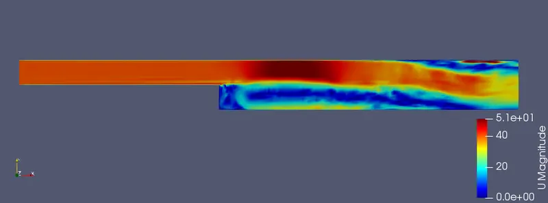
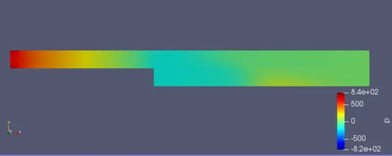
After running our simulation we can see our results in paraview and results are seen as below
Results:-
Velocity:-
Pressure:-
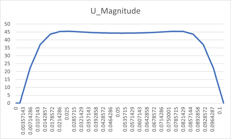
Plot over G.F= 1
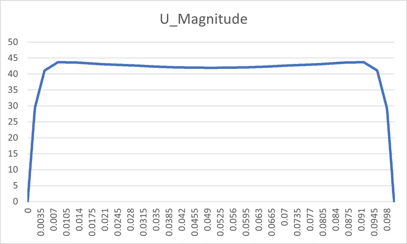
Plot over G.F = 0.2
Concluison:-
From the above two cases of G.F 1 and 0.2 we noticed that there is a change in the velocity profiles near the walls it is because of the boundary layer at noslip wall condition.
Therefore necesssary care should be taken in our mesh topology when such phenomenon is present.