Simulation of a backward facing step in OpenFOAM
QUES- In this challenge, you are going to simulate an incompressible-laminar-viscous flow through the backward facing step geometry. You should perform a transient simulation. The solver can be chosen based on the described physics of the flow. You need to explain the entire simulation procedure (how you set up the case). You should also provide explanations to every change you make inside the reference case files obtained from OpenFOAM tutorials.
Objective -
Case 1 - Simulate the flow without using any grading factor (i.e., GF = 1)
Case 2 - Simulate the flow with grading factor of 0.2. The cells should be finer near the walls (includig the step wall).
Theory-
Here the aim is simulate an incompressible-laminar-flow through backward facing step geometry. Accordingly need to select the solver respectively.
Solver - ICOFOAM
Futher since the solver uses PISO algorithm for continunity equa - `nabla*u=0`
Momentum equa - `del/(delt)(u)+nabla*(uoxu)-nabla*(v*nabla*u)=-nabla*p`
`u - Velocity`& `p`- Kinematic Pressure
Procedure-
1.Generate Blockmesh
- Geometry
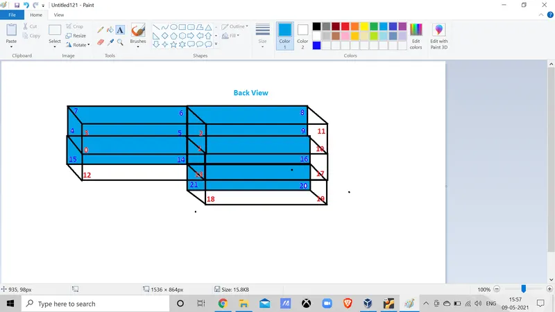
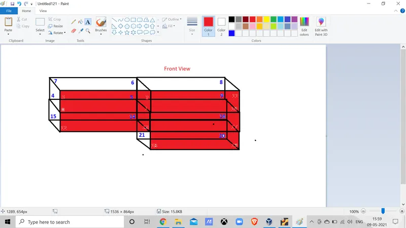
- Boundary
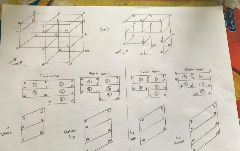
2.OpenFoam Script -
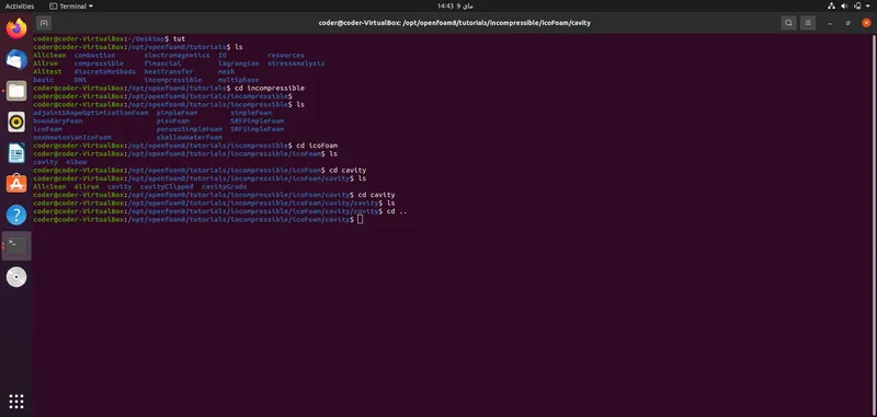
- To start the simulation process. Open the terminal on Ubuntu operating system by shortcut - Ctrl+alt+T or right click->Open terminal(4th from bottom).
- Enter short - 'tut' then 'ls' and it will take you to the in-built tutorial files present and display the file names.
- In our case we are solving an incompressible problem. So enter 'cd incompressible' followed by 'ls' it takes you to the solvers present in incompressible file.
- We are using solver IcoFoam. So enter 'cd icofoam' then 'ls' . Followed by another 'cd cavity'.
- Now copy the cavity file by -'cp -r cavity/$FOAM_RUN/cavity_test. It successful copies into a run folder and saves it as cavity_test.
- Note- Before copying make a new working directoty by 'mkdir Run_test' so that u dont mess up things.
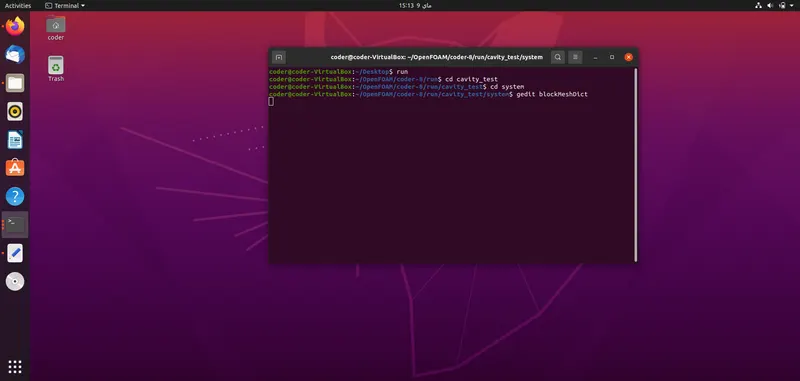
- Follow the commands to create blockMesh.
-----------------------------------------------------------------------------------------------------------------
Code
/*--------------------------------*- C++ -*----------------------------------*
  =========                 |
  \      /  F ield         | OpenFOAM: The Open Source CFD Toolbox
   \    /   O peration     | Website:  https://openfoam.org
    \  /    A nd           | Version:  8
     \/     M anipulation  |
*---------------------------------------------------------------------------*/
FoamFile
{
    version     2.0;
    format      ascii;
    class       dictionary;
    object      blockMeshDict;
}
// * * * * * * * * * * * * * * * * * * * * * * * * * * * * * * * * * * * * * //

convertToMeters 0.001;

vertices
(
    (0 0 0) //0
    (80 0 0)//1
    (80 5 0)//2
    (0 5 0)//3
    (0 0 1)//4
    (80 0 1)//5
    (80 5 1)//6
    (0 5 1)//7
    (200 5 1)//8
    (200 0 1)//9
    (200 0 0)//10
    (200 5 0)//11
    (0 -5 0)//12
    (80 -5 0)//13
    (80 -5 1)//14
    (0 -5 1)//15
    (200 -5 1)//16
    (200 -5 0)//17
    (80 -10 0)//18
    (200 -10 0)//19
    (200 -10 1)//20
    (80 -10 1)//21

);

blocks
(
    hex (0 1 2 3 4 5 6 7) (200 20 1) simpleGrading (1 1 1)
    hex (1 10 11 2 5 9 8 6) (200 20 1) simpleGrading (1 1 1)
    hex (12 13 1 0 15 14 5 4) (200 20 1) simpleGrading (1 1 1)
    hex (13 17 10 1 14 16 9 5) (200 20 1) simpleGrading (1 1 1)
    hex (18 19 17 13 21 20 16 14) (200 20 1) simpleGrading (1 1 1)

);

edges
(

);

boundary
(
    Inlet
    {
        type patch;
        faces
        (
            (3 0 4 7)
            (0 12 15 4)
        );
    }
    Outlet
    {
        type patch;
        faces
        (
            (11 10 9 8)
            (10 17 16 9)
            (17 19 20 16)
        );
    }
    fixedWalls
    {
        type wall;
        faces
        (
          (3 2 6 7)
          (2 11 8 6)
          (12 13 14 15)
          (18 19 20 21)
          (13 18 21 14)
        );
    }
    FrontAndBack
    {
        type empty;
        faces
        (
          (0 3 2 1) //Front
          (12 0 1 13)
          (18 13 17 19)
          (13 1 10 17)
          (1 2 11 10)

          (4 5 6 7)
          (15 14 5 4)
          (21 20 16 14)
          (5 9 8 6)

        );
    }
);

mergePatchPairs
(
);

// ************************************************************************* //
- The coordinace of the geometer are in meters. So we will use convertToMeters be 0.001
- Total vertices are 21. To define the vertices firstly set a origin and use x-,y-and z- coordinace for every verties.
- Now define the blocks of the mesh. Each block is a compound entry consisiting of list of vertice labels.
- So follow an orderly manner and giving the number of grids different-different such that one grid is 1mm.
- Use mergePatchPairs to merge the faces for creating % blocks and save it.
- In the terminal enter 'cd ..' one step back i.e out of 'system file' , enter 'blockMesh'
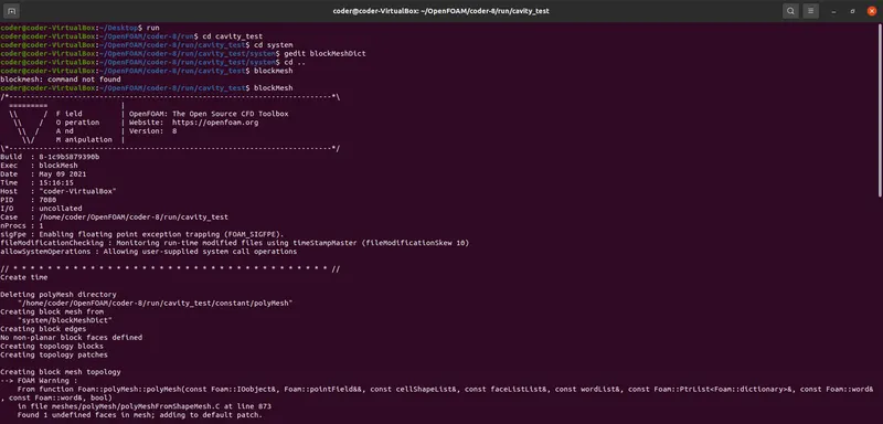
- Enter 'checkMesh' to know whether the created mesh is good or bad. Enter 'paraFoam' to check it in paraFoam.
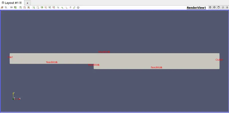
- Similarly define the inlet, outlet, fixedwalls(noSlip) and FrontAndback faces.
- Further define ControlDict,pressure,velocity and transportProperties, Just that the commands will be similar but the files for them will have different location.
/*--------------------------------*- C++ -*----------------------------------*
  =========                 |
  \      /  F ield         | OpenFOAM: The Open Source CFD Toolbox
   \    /   O peration     | Website:  https://openfoam.org
    \  /    A nd           | Version:  8
     \/     M anipulation  |
*---------------------------------------------------------------------------*/
FoamFile
{
    version     2.0;
    format      ascii;
    class       dictionary;
    location    "system";
    object      controlDict;
}
// * * * * * * * * * * * * * * * * * * * * * * * * * * * * * * * * * * * * * //

application     icoFoam;

startFrom       startTime;

startTime       0;

stopAt          endTime;

endTime         0.2;

deltaT          0.00001;

writeControl    timeStep;

writeInterval   20;

purgeWrite      0;

writeFormat     ascii;

writePrecision  6;

writeCompression off;

timeFormat      general;

timePrecision   6;

runTimeModifiable true;


// ************************************************************************* //
-----------------------------------------------------------------------------------------------------------------
/*--------------------------------*- C++ -*----------------------------------*
  =========                 |
  \      /  F ield         | OpenFOAM: The Open Source CFD Toolbox
   \    /   O peration     | Website:  https://openfoam.org
    \  /    A nd           | Version:  8
     \/     M anipulation  |
*---------------------------------------------------------------------------*/
FoamFile
{
    version     2.0;
    format      ascii;
    class       volScalarField;
    object      p;
}
// * * * * * * * * * * * * * * * * * * * * * * * * * * * * * * * * * * * * * //

dimensions      [0 2 -2 0 0 0 0];

internalField   uniform 0;

boundaryField
{
    Inlet
    {
        type           zeroGradient;
    }
    Outlet
    {
        type            fixedValue;
        value           uniform 0;
    }
    fixedWalls
    {
        type           zeroGradient;
    }

    frontAndBack
    {
        type            empty;
    }
}

// ************************************************************************* //
-----------------------------------------------------------------------------------------------------------------
/*--------------------------------*- C++ -*----------------------------------*
  =========                 |
  \      /  F ield         | OpenFOAM: The Open Source CFD Toolbox
   \    /   O peration     | Website:  https://openfoam.org
    \  /    A nd           | Version:  8
     \/     M anipulation  |
*---------------------------------------------------------------------------*/
FoamFile
{
    version     2.0;
    format      ascii;
    class       volVectorField;
    object      U;
}
// * * * * * * * * * * * * * * * * * * * * * * * * * * * * * * * * * * * * * //

dimensions      [0 1 -1 0 0 0 0];

internalField   uniform (0 0 0);

boundaryField
{
   Inlet
   {
     type        fixedValue;
     value       uniform (1 0 0);
   }
   Outlet
   {
     type       zeroGradient;

   }
   fixedWalls
   {
     type     noSlip;

   }
   frontAndBack
   {
     type    empty;
   }
}

// ************************************************************************* //
-----------------------------------------------------------------------------------------------------------------
/*--------------------------------*- C++ -*----------------------------------*
  =========                 |
  \      /  F ield         | OpenFOAM: The Open Source CFD Toolbox
   \    /   O peration     | Website:  https://openfoam.org
    \  /    A nd           | Version:  8
     \/     M anipulation  |
*---------------------------------------------------------------------------*/
FoamFile
{
    version     2.0;
    format      ascii;
    class       dictionary;
    location    "constant";
    object      transportProperties;
}
// * * * * * * * * * * * * * * * * * * * * * * * * * * * * * * * * * * * * * //

nu              [0 2 -1 0 0 0 0] 0.001;


// ************************************************************************* //
-----------------------------------------------------------------------------------------------------------------
Below is the BlockMesh created -
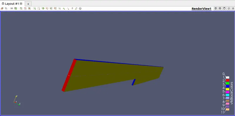
- To calculate the value type 'icoFoam' in terminal.Now when it solves the values do appear on the terminal.
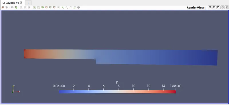
- To check the effect of pressure and velocity on the mesh. We are sipposed to see the mesh on paraview. Apply the properties and we can see on mesh's paraview. Also after playing the frame it shows at many different time frames.
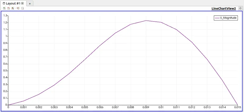
- Final plot the graph of mesh velocity at the line 0.085m.
- Incase of diifculty in plotting then refer to the text file present in videos section of OpenFoam.
3. Mesh -
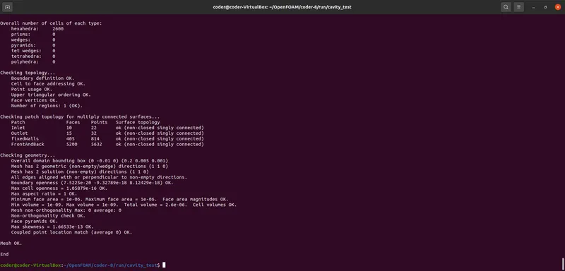
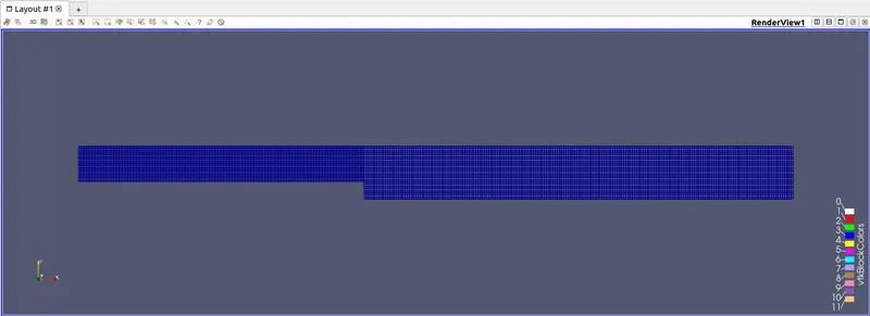
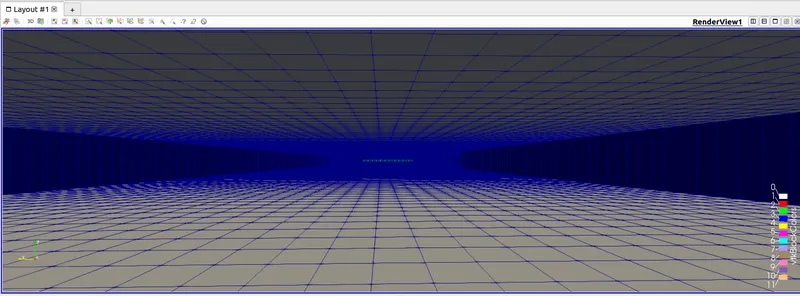
If we look at the below mesh. One can notice that mesh is not uniform all over the surface.Inorder to make it equal we can do the following changes-
-----------------------------------------------------------------------------------------------------------------
blocks
(
    hex (0 1 2 3 4 5 6 7) (80 5 1) simpleGrading (1 1 1)
    hex (1 10 11 2 5 9 8 6) (120 5 1) simpleGrading (1 1 1)
    hex (12 13 1 0 15 14 5 4) (80 5 1) simpleGrading (1 1 1)
    hex (13 17 10 1 14 16 9 5) (120 5 1) simpleGrading (1 1 1)
    hex (18 19 17 13 21 20 16 14) (120 5 1) simpleGrading (1 1 1)

);
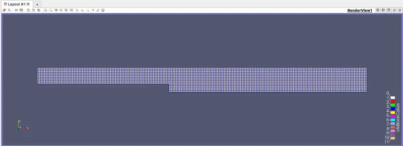
After the making the changes, now the mesh is uniformly distributed.
3.1.Mesh from inside-
FixedEnd-
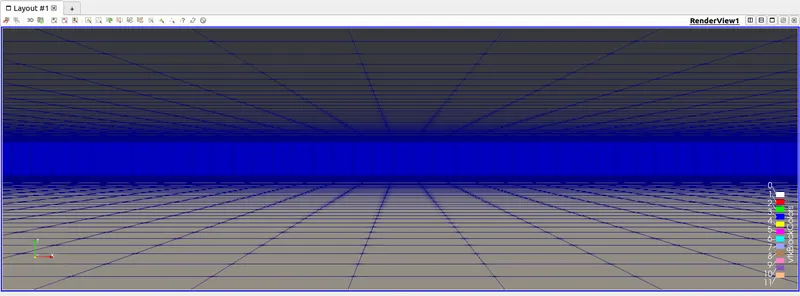
Inlet -
Results -
Case 1 - Grading factor =1
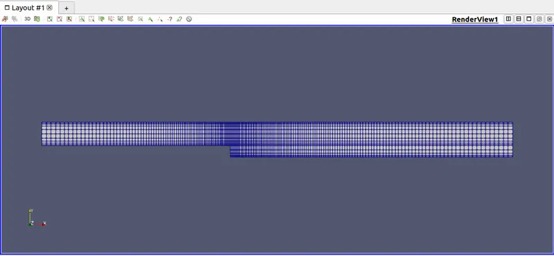
Mesh Grid
Velocity Distribution along the domain area with velocity at distance 0.085 from inlet
Velocity Plot
Pressure Distribution along the domain area
-----------------------------------------------------------------------------------------------------------------
Case 2 - Grading factor 0.2(cell near Fixed walls)
Code
/*--------------------------------*- C++ -*----------------------------------*
  =========                 |
  \      /  F ield         | OpenFOAM: The Open Source CFD Toolbox
   \    /   O peration     | Website:  https://openfoam.org
    \  /    A nd           | Version:  8
     \/     M anipulation  |
*---------------------------------------------------------------------------*/
FoamFile
{
    version     2.0;
    format      ascii;
    class       dictionary;
    object      blockMeshDict;
}
// * * * * * * * * * * * * * * * * * * * * * * * * * * * * * * * * * * * * * //

convertToMeters 0.001;

vertices
(
    (0 0 0) //0
    (80 0 0)//1
    (80 5 0)//2
    (0 5 0)//3
    (0 0 1)//4
    (80 0 1)//5
    (80 5 1)//6
    (0 5 1)//7
    (200 5 1)//8
    (200 0 1)//9
    (200 0 0)//10
    (200 5 0)//11
    (0 -5 0)//12
    (80 -5 0)//13
    (80 -5 1)//14
    (0 -5 1)//15
    (200 -5 1)//16
    (200 -5 0)//17
    (80 -10 0)//18
    (200 -10 0)//19
    (200 -10 1)//20
    (80 -10 1)//21

);

blocks
(
    hex (0 1 2 3 4 5 6 7) (80 5 1) simpleGrading (0.2 0.2 1) //Block1

    hex (1 10 11 2 5 9 8 6) (120 5 1) simpleGrading (5 0.2 1) //Block2

    hex (12 13 1 0 15 14 5 4) (80 5 1) simpleGrading (0.2 5 1) //Block3

    hex (13 17 10 1 14 16 9 5) (120 5 1) simpleGrading (5 5 1) //Block4

    hex (18 19 17 13 21 20 16 14) (120 5 1)  simpleGrading (5 5 1) //Block5
);

edges
(

);

boundary
(
    Inlet
    {
        type patch;
        faces
        (
            (3 0 4 7)
            (0 12 15 4)
        );
    }
    Outlet
    {
        type patch;
        faces
        (
            (11 10 9 8)
            (10 17 16 9)
            (17 19 20 16)
        );
    }
    fixedWalls
    {
        type wall;
        faces
        (
          (3 2 6 7)
          (2 11 8 6)
          (12 13 14 15)
          (18 19 20 21)
          (13 18 21 14)
        );
    }
    FrontAndBack
    {
        type empty;
        faces
        (
          (0 3 2 1) //Front
          (12 0 1 13)
          (18 13 17 19)
          (13 1 10 17)
          (1 2 11 10)

          (4 5 6 7)
          (15 14 5 4)
          (21 20 16 14)
          (14 16 9 5)
          (5 9 8 6)

        );
    }
);

mergePatchPairs
(
);

// ************************************************************************* //
Mesh generated by above Code
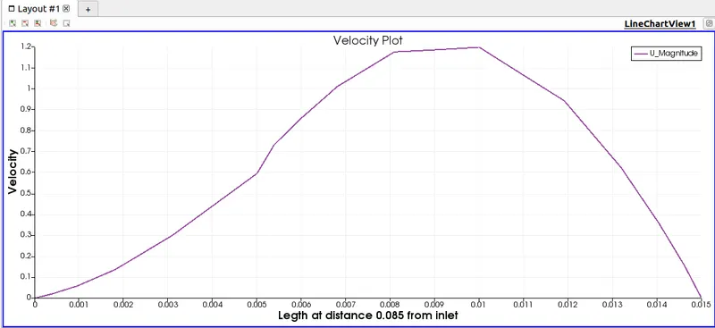
Velocity Distribution along domain area
Velocity Plot
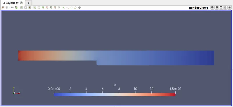
Pressure Distribution along domain area
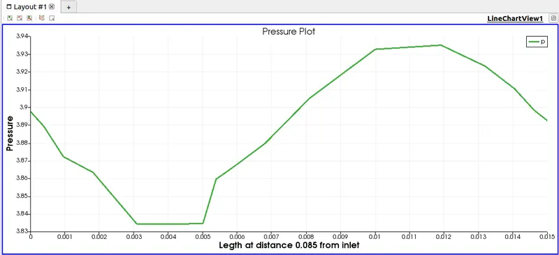
Pressure Plot
-----------------------------------------------------------------------------------------------------------------
Case 2 - Grading factor 0.2(cell near All walls)
Code
/*--------------------------------*- C++ -*----------------------------------*
  =========                 |
  \      /  F ield         | OpenFOAM: The Open Source CFD Toolbox
   \    /   O peration     | Website:  https://openfoam.org
    \  /    A nd           | Version:  8
     \/     M anipulation  |
*---------------------------------------------------------------------------*/
FoamFile
{
    version     2.0;
    format      ascii;
    class       dictionary;
    object      blockMeshDict;
}
// * * * * * * * * * * * * * * * * * * * * * * * * * * * * * * * * * * * * * //

convertToMeters 0.001;

vertices
(
    (0 0 0) //0
    (80 0 0)//1
    (80 5 0)//2
    (0 5 0)//3
    (0 0 1)//4
    (80 0 1)//5
    (80 5 1)//6
    (0 5 1)//7
    (200 5 1)//8
    (200 0 1)//9
    (200 0 0)//10
    (200 5 0)//11
    (0 -5 0)//12
    (80 -5 0)//13
    (80 -5 1)//14
    (0 -5 1)//15
    (200 -5 1)//16
    (200 -5 0)//17
    (80 -10 0)//18
    (200 -10 0)//19
    (200 -10 1)//20
    (80 -10 1)//21

);

blocks
(
    hex (0 1 2 3 4 5 6 7) (80 5 1)                    //Block1
    simpleGrading
    (
      (
        (0.5 0.5 5)//50 y-direc, 50% cells, expansion=5
        (0.5 0.5 0.2)//50 y-direc, 50% cells, expansion=0.2
      )
      (
        (0.2 0.1 1)//20 y-direc, 10% cells, expansion=1
        (0.8 0.9 0.2)//80 y-direc, 90% cells, expansion=0.2
      )
      1   //z-direction expansion ratio
    )
    hex (1 10 11 2 5 9 8 6) (120 5 1)                    //Block2
    simpleGrading
    (
      (
        (0.5 0.5 5) //50 y-direc, 50% cells, expansion=5
        (0.5 0.5 0.2)//50 y-direc, 50% cells, expansion=0.2
      )
      (
        (0.2 0.1 1)//20 y-direc, 10% cells, expansion=1
        (0.8 0.9 0.2)//80 y-direc, 90% cells, expansion=0.2
      )
      1   //z-direction expansion ratio
    )
    hex (12 13 1 0 15 14 5 4) (80 5 1)                    //Block3
    simpleGrading
    (
      (
        (0.5 0.5 5)//50 y-direc, 50% cells, expansion=5
        (0.5 0.5 0.2)//50 y-direc, 50% cells, expansion=0.2
      )
      (
        (0.8 0.9 0.2)//80 y-direc, 90% cells, expansion=0.2
        (0.2 0.1 1)//20 y-direc, 10% cells, expansion=1
      )
      1   //z-direction expansion ratio
    )
    hex (13 17 10 1 14 16 9 5) (120 5 1)                    //Block4
    simpleGrading
    (
      (
        (0.5 0.5 5)//50 y-direc, 50% cells, expansion=5
        (0.5 0.5 0.2)//50 y-direc, 50% cells, expansion=0.2
      )
      (
        (0.8 0.9 0.2)//80 y-direc, 90% cells, expansion=0.2
        (0.2 0.1 1)//20 y-direc, 10% cells, expansion=1
      )
      1   //z-direction expansion ratio
    )
    hex (18 19 17 13 21 20 16 14) (120 5 1)                    //Block5
    simpleGrading
    (
      (
        (0.5 0.5 5)//50 y-direc, 50% cells, expansion=5
        (0.5 0.5 0.2)//50 y-direc, 50% cells, expansion=0.2
      )
      (
        (0.9 0.9 5)//90 y-direc, 90% cells, expansion=5
        (0.1 0.1 1)//10 y-direc, 10% cells, expansion=1
      )
      1   //z-direction expansion ratio
    )

);

edges
(

);

boundary
(
    Inlet
    {
        type patch;
        faces
        (
            (3 0 4 7)
            (0 12 15 4)
        );
    }
    Outlet
    {
        type patch;
        faces
        (
            (11 10 9 8)
            (10 17 16 9)
            (17 19 20 16)
        );
    }
    fixedWalls
    {
        type wall;
        faces
        (
          (3 2 6 7)
          (2 11 8 6)
          (12 13 14 15)
          (18 19 20 21)
          (13 18 21 14)
        );
    }
    FrontAndBack
    {
        type empty;
        faces
        (
          (0 3 2 1) //Front
          (12 0 1 13)
          (18 13 17 19)
          (13 1 10 17)
          (1 2 11 10)

          (4 5 6 7)
          (15 14 5 4)
          (21 20 16 14)
          (14 16 9 5)
          (5 9 8 6)

        );
    }
);

mergePatchPairs
(
);

// ************************************************************************* //
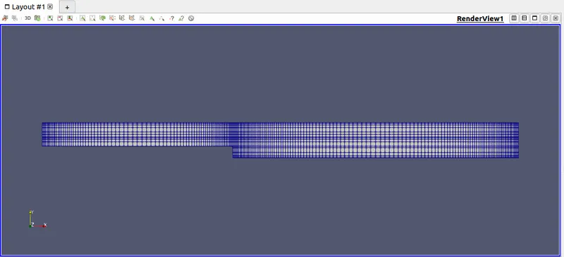
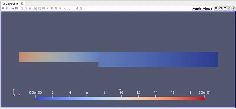
Mesh generated by above Code
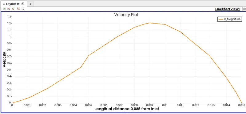
Velocity Distribution along the domain area
Velocity Plot
Pressure Distribution along the domain area
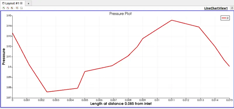
Pressure Plot
Inference from above results -
- From the above challenge, we have learnt to plotting velocity for both without and with Grading factor 0.2 cases.
- When we compare all velocity plot, one can that velocity plot without grading factor is more smooth and accurate than other 2 plots. From which we can assume that grading factor dispruts result.That isn't true, as it is noticable mesh is fine at step walll along X-axis whereas very coarse along Y-axis. Hence the reason for the velocity plot not to be smoot at distance 0.085 along Y-axis.
- Upto here we know how mesh actually works. One should keep in mind that using fine mesh near the point obtains a better reults.
- In CFD, fluids usually show large changes near the walls and obstacles along its way.
- To get efficaious results, one sholud know where to finer grading factor.
- In a bid to obtain results, one might supposedly use large number of fine element, which could lead to large computational time and memory allocation. Other wordds total wastage.
- Therefore, how to use grading factor is important.
- One should use fine mesh to capture flow at boundary walls and obstacles whereas coarse mesh for more open area.