Week 8 - Simulation of a backward facing step in OpenFOAM
Aim:- Aim of this challange is to perform a transient simulation of an incompressible-laminar-viscous flow through the backward facing step geometry in OpenFoam.
Objective:- The simualtion in OpenFoam is shuch that the inlet velocity of flow is laminar. and you have to compare result of two case studies
- Simulate the flow without using any grading factor (i.e., GF = 1)
- Simulate the flow with grading factor of 0.2. The cells should be finer near the walls (includig the step wall).
Mesh specification:-
- Number of cells along the x direction (longer dimension) = 200
- Number of cells along the longer y direction = 20
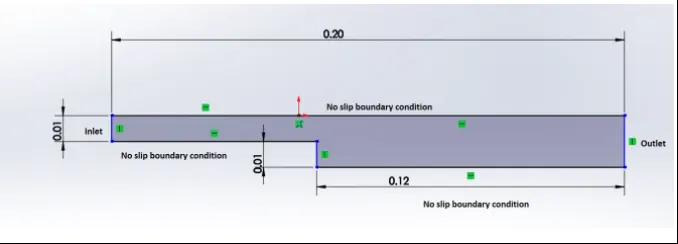
Boundary condition specification:- The domain specifications are provided in the following figure.
Procedure:-
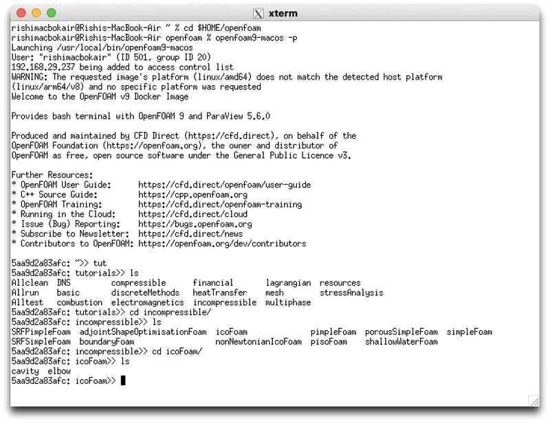
1) First open the terminal type cd $HOME/openfoam and press enter // Open foam directory is open now , then
Type openfoam9-macos -p // Now we run open foam in parafoam
Now open tutorial directory by typing tut enter, then type ls enter to show files and folders inside the tutorial directory.
now type cd incompressible enter and again type ls enter. Now you are in incompressible directory and you can se files and folder in this directory.
then go to icoFoam directory by same procedure as above. Now again type ls enter and you can see cavity folder inside it.
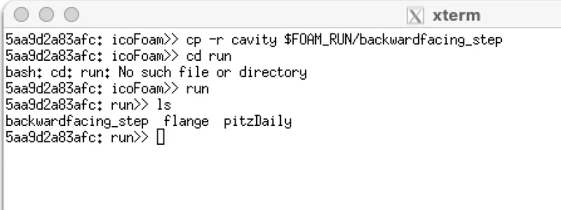
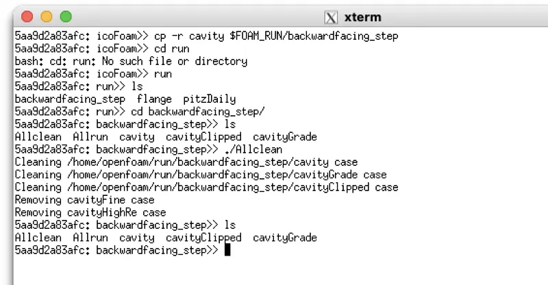
2). Now we copy this directory in our run folder so type cp -r cavity $FOAM_RUN/backwarfacing_step and press enter.
here you copy yours cavity folder as backwardfacing_step in run folder .
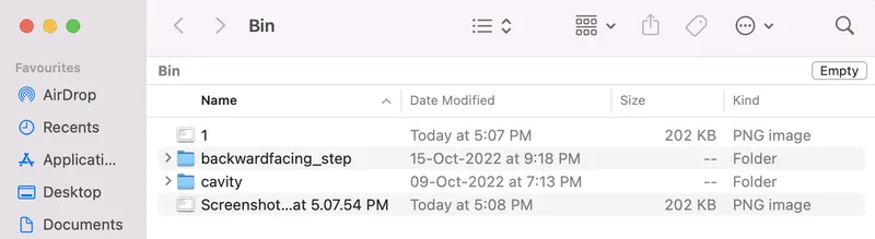
3). Now if you open this backwardfacing_step and you find folder cavity in which you find 0,constan and system folder. if you find other folder like 0.1 etc so type ./Allclean to clean then privious analysis result.
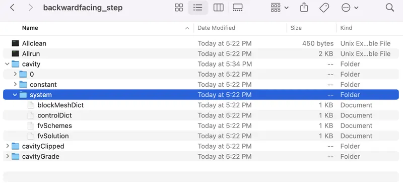
4). Now go to the system folder and open blockMeshDict file
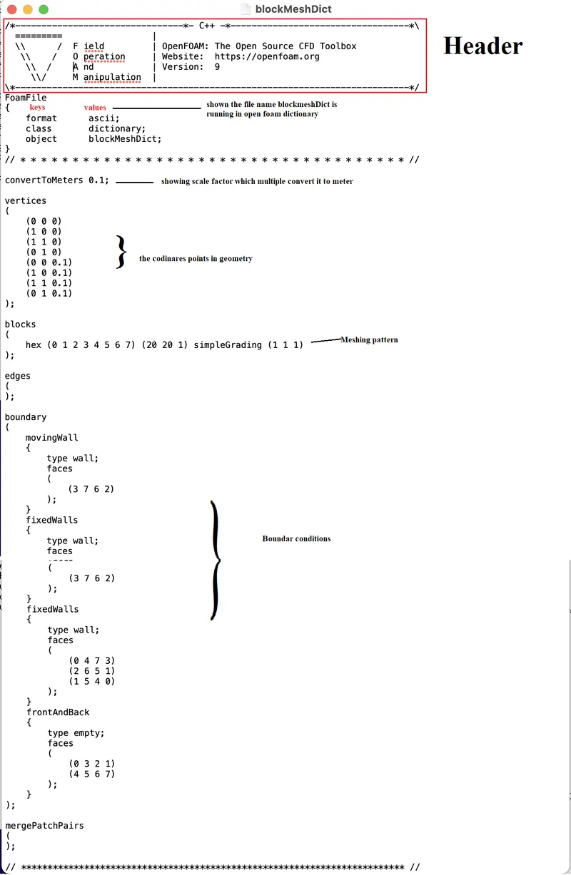
Now you can see in this bolockMeshDict file
upper portion is show header ( open foam version information), then you can see file information i.e. in which formates it is running and in what is its class. the class dictionary means it follows cpp dictionary to write program.
Now compes to our challange we have to creates a block mesh like this image
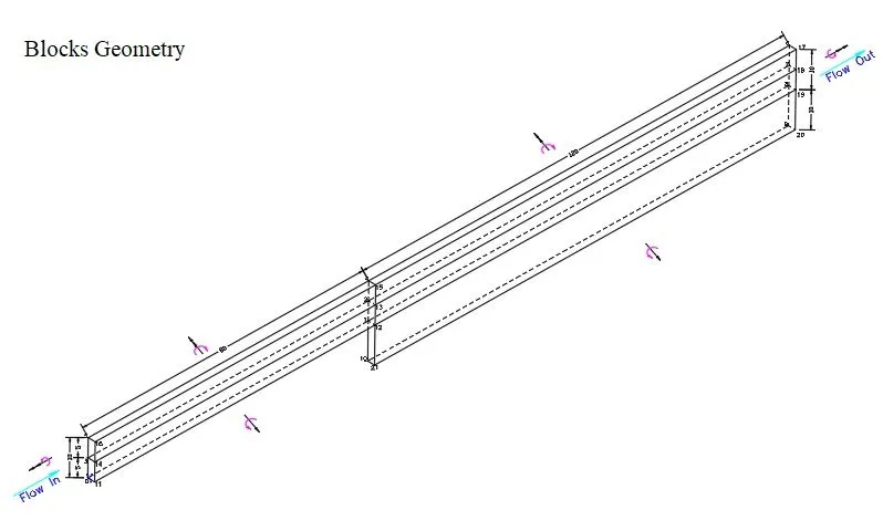
a) Define vertices:- The above image is wireframe model of our block mesh project which dimension is taken from the challange image, here we have give only 2d dimension and i assume block wall thickness 1mm. here in image the given values in meter so i gave sclae factor of 0.001 in my program.
Now i gives my coordinate values vertices in mm as shown in below image
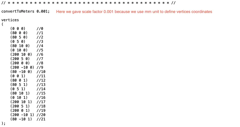
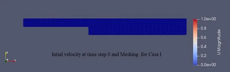
b) Define meshing block:- In the above progarm we define number of grids in x dirction is 200 in each block and 20 in y direction. in z direction we assine only one grid. and as per our case study we define grading by facor 1 in each direction i.e. in each direction grid generation is constan or we can say grids are equal in size at start and end.
The pattern of define mesh in openFoam is
Element type (Vertex numbering) (Number of cell in x,y and z direction) Grading type(GF in x,y and z direction)
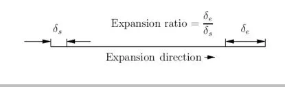
Cell expansion ratios or Grading factor (GF):- The expansion ratio enables the mesh to be graded, or refined, in specified directions. The ratio is that of the width of the end cell  along one edge of a block to the width of the start cell
  along that edge.
For simple grading we have to define GF in x,y and z direction only but in edge grading we have to define it for each edge.
Case 1 - Simulate the flow without using any grading factor (i.e., GF = 1)
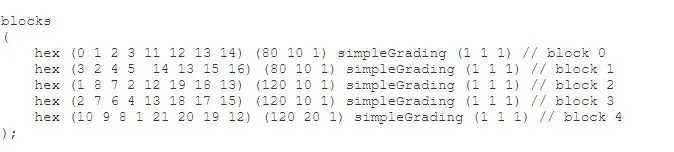
in this case each element of size in x direction is 1 mm and in y direction 0.5.

Case 2 - Simulate the flow with grading factor of 0.2. The cells should be finer near the walls (includig the step wall).
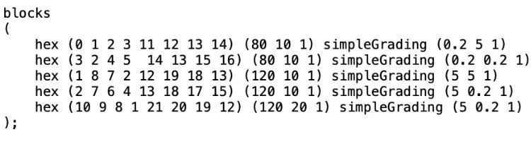
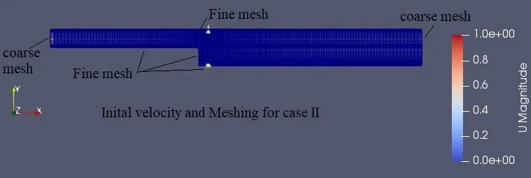
in this case in first block in x direction GF is 0.2 and in y direction GF is 5 , This is why ecause here cells should be finer near the walls have finer mesh, so in x direction (.i.e on edge 0 to 1 ) the ratio cell size at vertic 1 and cell size at veric 0 is 0.2.And ratio of cell size at 3 and 0 is 5 i.e. edge '32' have coarce mesh then edge '01'. Similary we apply grading on other blocks.
C) Define Boundaries:- Now we define boundaries inlet , outlet, fixed walls and front and back faces in shuch a way if we apply Rigth hand thumb rule the direction of thumb is outward to each face and direction of fingure is given sqeuence of coner point of that face to define it as shoen in above image of Blockes geometry.
Copy files for caeII
first go to run directory in terminal and copy backwordfacing_step folder as new name case 2 in root directory.

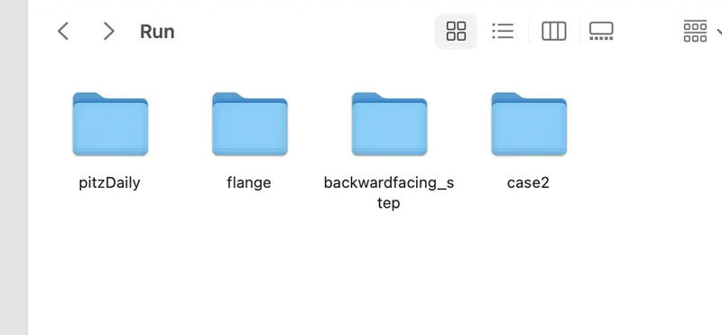
Now edith both case blockMeshDict file and controlDict fiels.
blockMeshDict for Case I
/*--------------------------------*- C++ -*----------------------------------*\
  =========                 |
  \\      /  F ield         | OpenFOAM: The Open Source CFD Toolbox
   \\    /   O peration     | Website:  https://openfoam.org
    \\  /    A nd           | Version:  9
     \\/     M anipulation  |
\*---------------------------------------------------------------------------*/
FoamFile
{
    format      ascii;
    class       dictionary;
    object      blockMeshDict;
}
// * * * * * * * * * * * * * * * * * * * * * * * * * * * * * * * * * * * * * //

convertToMeters 0.001;

vertices
(
    (0 0 0)     //0
    (80 0 0)    //1
    (80 5 0)    //2
    (0 5 0)     //3
    (80 10 0)   //4
    (0 10 0)    //5
    (200 10 0)  //6
    (200 5 0)   //7
    (200 0 0)   //8
    (200 -10 0) //9
    (80 -10 0)  //10
    (0 0 1)     //11
    (80 0 1)    //12
    (80 5 1)    //13
    (0 5 1)     //14
    (80 10 1)   //15
    (0 10 1)    //16
    (200 10 1)  //17
    (200 5 1)   //18
    (200 0 1)   //19
    (200 -10 1) //20
    (80 -10 1)  //21
);

blocks
(
    hex (0 1 2 3 11 12 13 14) (80 10 1) simpleGrading (1 1 1) // block 0
    hex (3 2 4 5  14 13 15 16) (80 10 1) simpleGrading (1 1 1) // block 1
    hex (1 8 7 2 12 19 18 13) (120 10 1) simpleGrading (1 1 1) // block 2
    hex (2 7 6 4 13 18 17 15) (120 10 1) simpleGrading (1 1 1) // block 3
    hex (10 9 8 1 21 20 19 12) (120 20 1) simpleGrading (1 1 1) // block 4
);

edges
(
);

boundary
(
  Inlet                   // patch 0
  {
      type patch;
      faces
      (
         (0 11 14 3)      // face 1
         (3 14 16 5)      // face 2
      );
   }
  FixedWalls             // patch 1
  {
      type wall;
      faces
      (
         (4 5 16 15)      // face 1
         (6 4 15 17)      // face 2
         (0 1 12 11)      // face 3
         (1 10 21 12)     // face 4
         (10 9 20 21)     // face 5
      );
   }
  Outlet                 // patch 2
  {
      type patch;
      faces
      (
         (6 17 18 7)     // face 1
         (7 18 19 8)     // face 2
         (8 19 20 9)     // face 3
      );
   }
  FrontAndBack          // patch 3
  {
      type empty;
      faces
      (
         (3 2 1 0)     // face 1
         (5 4 2 3)     // face 2
         (1 8 9 10)    // face 3
         (2 7 8 1)     // face 4
         (4 6 7 2)     // face 5
         (11 12 13 14)     // face 6
         (14 13 15 16)     // face 7
         (21 20 19 12)     // face 8
         (12 19 18 13)     // face 9
         (13 18 17 15)     // face 10
      );
   }
);

mergePatchPairs
(
);

// ************************************************************************* //
blockMeshDict for Case II
/*--------------------------------*- C++ -*----------------------------------*\
  =========                 |
  \\      /  F ield         | OpenFOAM: The Open Source CFD Toolbox
   \\    /   O peration     | Website:  https://openfoam.org
    \\  /    A nd           | Version:  9
     \\/     M anipulation  |
\*---------------------------------------------------------------------------*/
FoamFile
{
    format      ascii;
    class       dictionary;
    object      blockMeshDict;
}
// * * * * * * * * * * * * * * * * * * * * * * * * * * * * * * * * * * * * * //

convertToMeters 0.001;

vertices
(
    (0 0 0)     //0
    (80 0 0)    //1
    (80 5 0)    //2
    (0 5 0)     //3
    (80 10 0)   //4
    (0 10 0)    //5
    (200 10 0)  //6
    (200 5 0)   //7
    (200 0 0)   //8
    (200 -10 0) //9
    (80 -10 0)  //10
    (0 0 1)     //11
    (80 0 1)    //12
    (80 5 1)    //13
    (0 5 1)     //14
    (80 10 1)   //15
    (0 10 1)    //16
    (200 10 1)  //17
    (200 5 1)   //18
    (200 0 1)   //19
    (200 -10 1) //20
    (80 -10 1)  //21
);

blocks
(
    hex (0 1 2 3 11 12 13 14) (80 10 1) simpleGrading (0.2 5 1) // block 0
    hex (3 2 4 5  14 13 15 16) (80 10 1) simpleGrading (0.2 0.2 1) // block 1
    hex (1 8 7 2 12 19 18 13) (120 10 1) simpleGrading (5 5 1) // block 2
    hex (2 7 6 4 13 18 17 15) (120 10 1) simpleGrading (5 0.2 1) // block 3
    hex (10 9 8 1 21 20 19 12) (120 20 1) simpleGrading (5 0.2 1) // block 4
);

edges
(
);

boundary
(
  Inlet                   // patch 0
  {
      type patch;
      faces
      (
         (0 11 14 3)      // face 1
         (3 14 16 5)      // face 2
      );
   }
  FixedWalls             // patch 1
  {
      type wall;
      faces
      (
         (4 5 16 15)      // face 1
         (6 4 15 17)      // face 2
         (0 1 12 11)      // face 3
         (1 10 21 12)     // face 4
         (10 9 20 21)     // face 5
      );
   }
  Outlet                 // patch 2
  {
      type patch;
      faces
      (
         (6 17 18 7)     // face 1
         (7 18 19 8)     // face 2
         (8 19 20 9)     // face 3
      );
   }
  FrontAndBack          // patch 3
  {
      type empty;
      faces
      (
         (3 2 1 0)     // face 1
         (5 4 2 3)     // face 2
         (1 8 9 10)    // face 3
         (2 7 8 1)     // face 4
         (4 6 7 2)     // face 5
         (11 12 13 14)     // face 6
         (14 13 15 16)     // face 7
         (21 20 19 12)     // face 8
         (12 19 18 13)     // face 9
         (13 18 17 15)     // face 10
      );
   }
);

mergePatchPairs
(
);

// ************************************************************************* //
save the blockMeshDict file and go to the terminal Type bockMesh and Enter

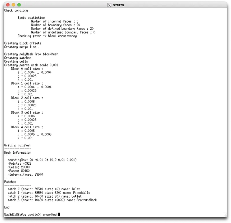
Now we get 4 patch i.e. boundaries and no error is found now chech the mesh by checkMesh Enter in terminal
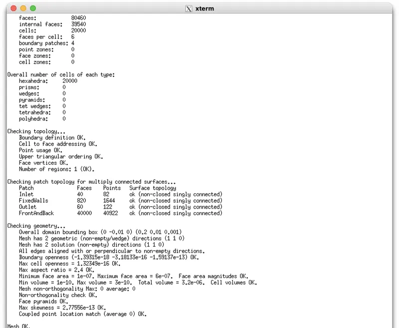
Note: procedure of blockMesh and checkMesh is not same in both the case so try this in diffrent terminals and sparatly.
# Boundary condition defination
Now go to '0' folder and open P and U file
/*--------------------------------*- C++ -*----------------------------------*\
  =========                 |
  \\      /  F ield         | OpenFOAM: The Open Source CFD Toolbox
   \\    /   O peration     | Website:  https://openfoam.org
    \\  /    A nd           | Version:  9
     \\/     M anipulation  |
\*---------------------------------------------------------------------------*/
FoamFile
{
    format      ascii;
    class       volScalarField;
    object      p;
}
// * * * * * * * * * * * * * * * * * * * * * * * * * * * * * * * * * * * * * //

dimensions      [0 2 -2 0 0 0 0];

internalField   uniform 0;

boundaryField
{
    Inlet
    {
        type            zeroGradient;
    }

    FixedWalls
    {
        type            zeroGradient;
    }

    Outlet
    {
        type            fixedValue;
        value           uniform 0;
    }

    FrontAndBack
    {
        type            empty;
    }
}

// ************************************************************************* //
Here for pressure inlet value is undefined so use zerogradient and for outlet its value is atmospheric pressure so we put 0 ( because here it is gauge pressure )
/*--------------------------------*- C++ -*----------------------------------*\
  =========                 |
  \\      /  F ield         | OpenFOAM: The Open Source CFD Toolbox
   \\    /   O peration     | Website:  https://openfoam.org
    \\  /    A nd           | Version:  9
     \\/     M anipulation  |
\*---------------------------------------------------------------------------*/
FoamFile
{
    format      ascii;
    class       volVectorField;
    object      U;
}
// * * * * * * * * * * * * * * * * * * * * * * * * * * * * * * * * * * * * * //

dimensions      [0 1 -1 0 0 0 0];

internalField   uniform (0 0 0);

boundaryField
{
    Inlet
    {
        type            fixedValue;
        value           uniform (1 0 0);
    }

    FixedWalls
    {
        type            noSlip;
    }
    Outlet
    {
	type		zeroGradient;
    }

    FrontAndBack
    {
        type            empty;
    }
}

// ************************************************************************* //
here inlet velociy is consta and equal to 1m/s.
Note: P and U files are same in bothe casses.
# Time step defination
Now open controlDict file (for case I)
/*--------------------------------*- C++ -*----------------------------------*\
  =========                 |
  \\      /  F ield         | OpenFOAM: The Open Source CFD Toolbox
   \\    /   O peration     | Website:  https://openfoam.org
    \\  /    A nd           | Version:  9
     \\/     M anipulation  |
\*---------------------------------------------------------------------------*/
FoamFile
{
    format      ascii;
    class       dictionary;
    location    "system";
    object      controlDict;
}
// * * * * * * * * * * * * * * * * * * * * * * * * * * * * * * * * * * * * * //

application     icoFoam;

startFrom       startTime;

startTime       0;

stopAt          endTime;

endTime         0.5;

deltaT          0.001;

writeControl    timeStep;

writeInterval   20;

purgeWrite      0;

writeFormat     ascii;

writePrecision  6;

writeCompression off;

timeFormat      general;

timePrecision   6;

runTimeModifiable true;


// ************************************************************************* //
Now when run progarma by typing icoFoam Enter
Now openfoam run the analysis in terminal you can see iterative solver solve equation for time step 0.001,0.002,0.003 and so on.
during the analysis if you see CFL number in any time step is out of the our stablity criteria then after some time step it show nan value in CFL as well as in residual and results also.
CFL No.- `mu (△ t)/(△ x)`
now here in case I, dx is 1 mm and dy is 0.5 and it is constant through out length.so we take dt in such a way it CFL number is less then 0.5 in all time step.
mu=1e-5
△t=0.001
ControlDict file (for case II)
now here in case II, dx and dy are varible through length, and becuase of this at run time it cause nan error at △t=0.001 so i change △t=0.0005.
Now our end time i choose i such a way it take sutaible time for analysis. in both case i but end time 0.5
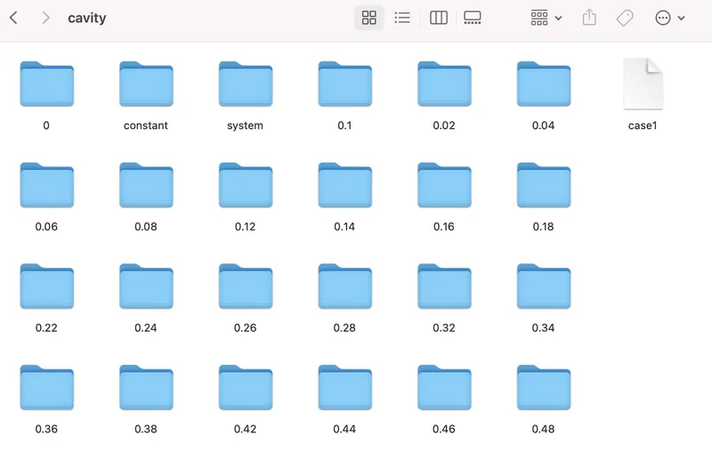
In first case total time steps is 0.5/0.001=500, so write intervel 20 creates 25 folder in cavity directory have data of that time step.
In second case total time steps is0.5/0.005=1000, so write intervel is 50 creats 20 folder in cavity directory have data of that time step.
/*--------------------------------*- C++ -*----------------------------------*\
  =========                 |
  \\      /  F ield         | OpenFOAM: The Open Source CFD Toolbox
   \\    /   O peration     | Website:  https://openfoam.org
    \\  /    A nd           | Version:  9
     \\/     M anipulation  |
\*---------------------------------------------------------------------------*/
FoamFile
{
    format      ascii;
    class       dictionary;
    location    "system";
    object      controlDict;
}
// * * * * * * * * * * * * * * * * * * * * * * * * * * * * * * * * * * * * * //

application     icoFoam;

startFrom       startTime;

startTime       0;

stopAt          endTime;

endTime         0.5;

deltaT          0.0005;

writeControl    timeStep;

writeInterval   50;

purgeWrite      0;

writeFormat     ascii;

writePrecision  6;

writeCompression off;

timeFormat      general;

timePrecision   6;

runTimeModifiable true;


// ************************************************************************* //
# Run the solver
Now go to termnal and come to cavity directory of backwarfaing_step type icoFoam and ENTER

Now type ls enter, you can see each time step file come in to the cavity folder

Now solver is running and it show parameter value of each time step in terminal and save the data for define time step in cavity directory. Now when solution is done for save it type touch file name it save file in cavity folder.
for case II clear all command interminal by clear enter and then go to case 2 directory and run analysis by tryping icoFoam enter

# Postprocdure and ploting results
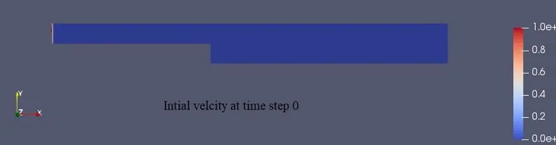
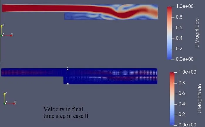
Now type paraFoam to open result in ParaView , First select cavity in tree then select U (velocity) and click Apply. For both the case it look like below image . Here defult surfece is there for show mesh click surface and edge.
# Meshing for case I
# Meshing for case II
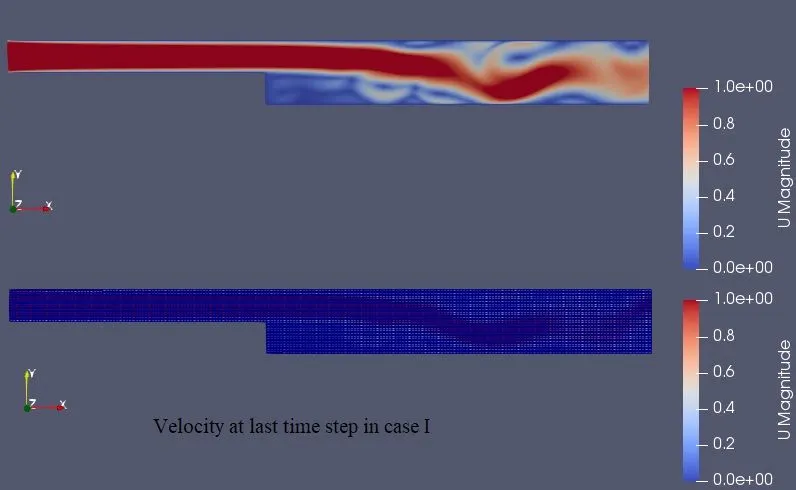
# Flow Velocity pattern in x direction in caseI at final time step
# Flow Velocity pattern in x direction in caseII at final time step
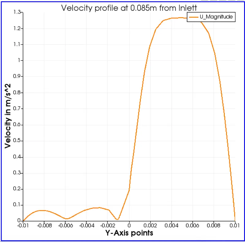
# Ploting Result: Velocity profile at 0.085m from inlet
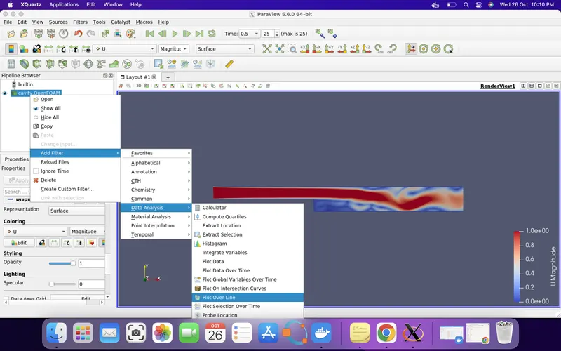
for this Right click Cavity in tree select Add filter in dropdown list, select Data Analysist then click plot over line
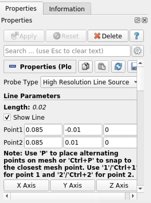
Now define that line on which you have to plot velocity profile
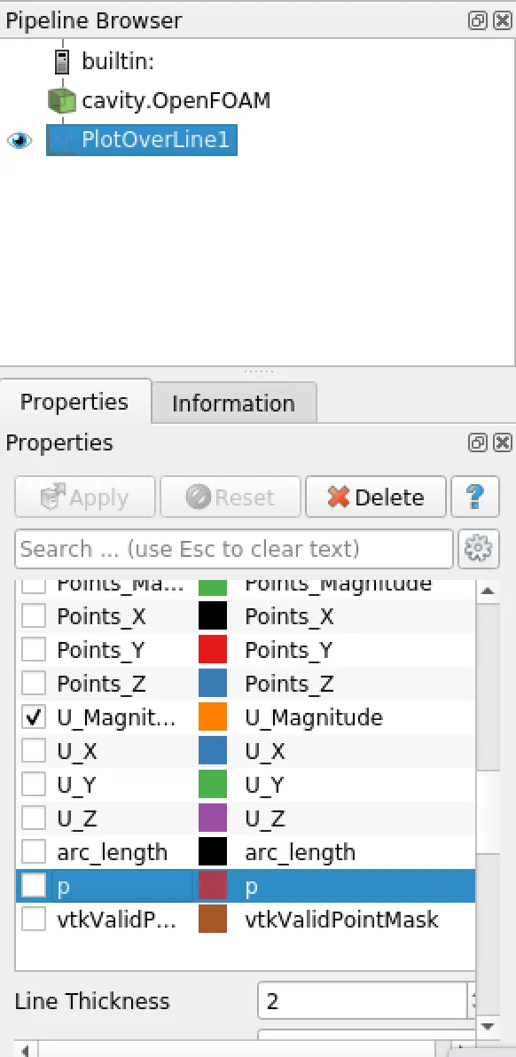
Now click Apply and select output parameters (i.e. velocity )
The plots results are
CASE I
CASE II
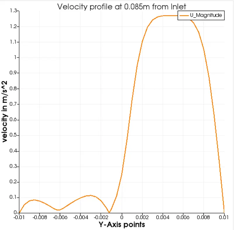
Now if we compare both the profile you can see velocity is very less in both profile at y=-0.01 to -0.002. because these point are in block 4 and flow is coming fron block 0 and 1 and it is suddnly expaning in block 2,3 &4.so in both the case you see a small pick and down in block 4.
But here you clearly see in both case a suddend peeak in block 2 and 3 (i.e. after -0.002 to 0.01). this peofile because flow is directly comming to block 2 and 3 from block0 and 1.At Y-axis point 0.005 or at mind point of flow so here effect of viscosity is low so velocity is at is peak in voth casses but in case II where mesh is soomth at interface bounday of block 2 and 3 i.e. intermidiate face(2 7 13 18) so velocity profile is also smmoth at peak in caseII.
Flow in time span 0.5 min for case I (Uniform mesh)
Flow in time span 0.5 min for case II (Nonuniform mesh)
# why we need gradding
Now in both the case you observe flow velociy is more at center and less at wall face this is because of viscosity which foam boundary layer as shwon in figure
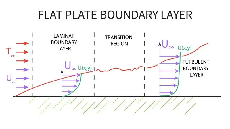
Because of this bounday layer in flow while CFD analysis we need to refine mesh at wall so we do grading in meshing as you can see in caseII.
Conclusion:-
- In this challange we learn how to creat and mesh geometry in openfoam.
- In this challange we understood comcept of grading factor and how it effect the flow.
- In this challange we also learn how to define boundaries condition in openfoam.
- In this challange we also learn what time step is sutable for stable solution in transient analysis in openfoam.
- In this challange we also learn how to measre velocity profile in paraview.