Week 8 - Simulation of a backward facing step in OpenFOAM
SIMULATION OF A BACKWARD FACING STEP IN OpenFOAM
AIM:
- Simulate an incompressible-laminar-viscous flow through the backward-facing step geometry.
- Perform transient simulation; choose solver based on the described flow physics in the problem statement.
- Explain the simulation process and way of setting up the problem statement in OpenFOAM and also, explain every change done inside the reference case files obtained from OpenFOAM tutorials.
- Next, perform two case studies, firstly, form a simulation of the flow without using any grading factor (i.e., GF = 1). Secondly, simulate the flow with a grading factor of 0.2. The cells should be finer near the walls (including the step wall).
OBJECTIVE:
- Open OpenFOAM tutorials and find the solver to solve incompressible-laminar-viscous flow problems.
- The next step is to copy the required file in the solver and paste it into the OpenFOAM run folder so that the official file of OpenFoam remains untouched.
- Find out the block mesh script file to create domain space and provide mesh specification.
- Find the ‘controlDict' file to edit start and end times for simulation.
- In the initial folder ‘0’ edit the initial parameter for velocity and pressure according to the faces of the given domain.
- Use 'blockMesh' command to generate a mesh and 'checkMesh' command to verify it.
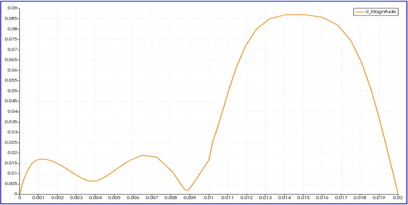
- Open the simulation file in ParaView and plot the velocity profile at point 0.085m from the inlet.
- Repeat the above procedure for grading factor 0.2 to check the differences in results.
THEORY:
Incompressible-laminar-viscous flow:
Incompressible flow: a flow in which the material density is constant within a fluid parcel. That is, a flow in which the fluid volume does not change is called incompressible flow.
Laminar flow: A laminar flow is one where the fluid motion is regular and there is no mixing. It can be visualized by the pathlines that do not intersect each other.
Viscous flow: the fluid flow in form of layers. The layer which sticks with the wall has zero velocity which is called the no-slip condition and it develops the frictional effect at the wall. Frictional effects are also present between two layers of fluid and the slower layer tries to slow down the faster layer which can be measured by using viscosity. The flow region near the walls is called the viscous flow region. The velocity is high in the middle region due to less frictional effect from walls. The flow in this region is called inviscid flow.
Mesh Grading: it is the ratio of the size of the end mesh cell to the size of the starting mesh cell.
Mesh Grading = (size of end cell) / (size of starting cell)
Problem Statement:
Simulate an incompressible-laminar-viscous flow through the backward-facing step geometry.
perform 2 case studies as described below and compare the results.
Case 1 - Simulate the flow without using any grading factor (i.e., GF = 1)
Case 2 - Simulate the flow with a grading factor of 0.2. The cells should be finer near the walls (including the step wall).
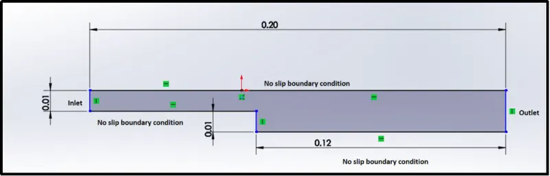
The backward-facing step geometry is created using 5 blocks.
the 5 blocks are formed from 21 vertices taken as follow,
PROCEDURE:
STEP-1: Open OpenFOAM tutorials and find the solver to solve incompressible-laminar-viscous flow problems and copy the required file in the solver and paste it into the OpenFOAM run folder so that the official file of OpenFoam remains untouched.
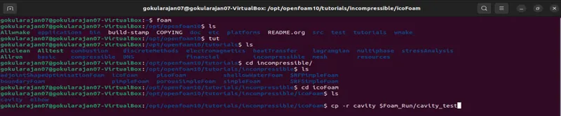
- Open the terminal window using the keyboard shortcut alt + ctrl + T.
- Inside the OpenFoam tutorials folder, the incompressible/icoFoam/cavity module is selected.
- the cavity directory is copied to the OpenFoam Run folder.
STEP-2: Find out the block mesh script file and the controlDict file locations to edit for simulation.
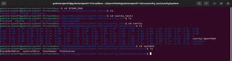
- Open the OpenFoam Run folder and navigate to the system directory as shown above.
- Inside the system directory, are blockMeshDict and controlDict files.
- The gedit command is used to edit those files.
- The domain space and mesh specification are fed in the blockMeshDict file.
- There are 21 vertices and 5 blocks while creating blocks we also need to specify the number of mesh points needed along the x, y, and z-direction, and also the simple grading should be done along the boundaries.
- Assign the boundary conditions here, we need to define all the faces in OpenFOAM and give their type that is the inlet and outlet will be the faces (type patch), for front and back type will be empty faces, for top and bottom which are the boundary conditions in this case type will be wall type and setting up these will constitute a particular boundary, then will save these changes in the blockMeshDict.
- The end time and difference in timestep are fed in the controlDict file.
- the simulation time and the time step need to be assigned in the way that the courant number should be less than 0.5.
blockMeshDict file
/*--------------------------------*- C++ -*----------------------------------*
  =========                 |
  \      /  F ield         | OpenFOAM: The Open Source CFD Toolbox
   \    /   O peration     | Website:  https://openfoam.org
    \  /    A nd           | Version:  10
     \/     M anipulation  |
*---------------------------------------------------------------------------*/
FoamFile
{
    format      ascii;
    class       dictionary;
    object      blockMeshDict;
}
// * * * * * * * * * * * * * * * * * * * * * * * * * * * * * * * * * * * * * //

convertToMeters 0.01;

vertices
(
    //BackFace
    (0 0 0)    //0
    (8 0 0)    //1
    (8 0.5 0)  //2
    (0 0.5 0)  //3
    (8 1 0)    //4
    (0 1 0)    //5
    (20 1 0)   //6
    (20 0.5 0) //7
    (20 0 0)   //8
    (20 -1 0)  //9
    (8 -1 0)   //10

    //FrontFace
    (0 0 0.6)    //11
    (8 0 0.6)    //12
    (8 0.5 0.6)  //13
    (0 0.5 0.6)  //14
    (8 1 0.6)    //15
    (0 1 0.6)    //16
    (20 1 0.6)   //17
    (20 0.5 0.6) //18
    (20 0 0.6)   //19
    (20 -1 0.6)  //20
    (8 -1 0.6)   //21

);

blocks
(
    hex (0 1 2 3 11 12 13 14) (80 10 1) simpleGrading (1 1 1)   //block 1
    hex (3 2 4 5 14 13 15 16) (80 10 1) simpleGrading (1 1 1)   //block 2
    hex (2 7 6 4 13 18 17 15) (120 10 1) simpleGrading (1 1 1)  //block 3
    hex (1 8 7 2 12 19 18 13) (120 10 1) simpleGrading (1 1 1)  //block 4
    hex (10 9 8 1 21 20 19 12) (120 20 1) simpleGrading (1 1 1) //block 5
);

edges
(

);

boundary
(
    inlet
    {
        type patch;
        faces
        (
            (0 11 14 3)
            (3 14 16 5)
        );
    }

    outlet
    {
        type patch;
        faces
        (
            (9 8 19 20)
            (8 7 18 19)
            (7 6 17 18)

        );
    }


    frontAndBack
    {
        type empty;
        faces
        (
            (0 3 2 1)
            (11 12 13 14)
            (3 5 4 2)
            (13 15 16 14)
            (2 4 6 7)
            (13 18 17 15)
            (1 2 7 8)
            (12 19 18 13)
            (10 1 8 9)
            (21 20 19 12)
        );
    }

    noSlipWalls
    {
        type wall;
        faces
        (
            (4 5 16 15)
            (4 15 17 6)
            (0 1 12 11)
            (9 20 21 10)
            (1 10 21 12)
        );
    }
);

mergePatchPairs
(

);


// ************************************************************************* //
controlDict file
/*--------------------------------*- C++ -*----------------------------------*
  =========                 |
  \      /  F ield         | OpenFOAM: The Open Source CFD Toolbox
   \    /   O peration     | Website:  https://openfoam.org
    \  /    A nd           | Version:  10
     \/     M anipulation  |
*---------------------------------------------------------------------------*/
FoamFile
{
    format      ascii;
    class       dictionary;
    location    "system";
    object      controlDict;
}
// * * * * * * * * * * * * * * * * * * * * * * * * * * * * * * * * * * * * * //

application     icoFoam;

startFrom       startTime;

startTime       0;

stopAt          endTime;

endTime         3;

deltaT          1e-3;

writeControl    timeStep;

writeInterval   20;

purgeWrite      0;

writeFormat     ascii;

writePrecision  6;

writeCompression off;

timeFormat      general;

timePrecision   6;

runTimeModifiable true;


// ************************************************************************* //
STEP-3: Find and edit the initial pressure and velocity files

- Navigate to the '0' directory as shown above.
- Inside the '0' directory we can find the files for initial pressure (p) and initial velocity (U).
- Use the gedit command to edit those files.
- Then, in the velocity and pressure files, we have to give the value of the velocity at the inlet type will be a fixed value here we should assign some value as initial velocity and pressure will be zerogradient and at the outlet velocity type will be zerogradient and pressure will be type fixed value that value will be uniform 0, then at front and back the velocity is type empty and pressure, as well as type empty at the no-slip boundaries that is top and bottom velocity, will be type no-slip and pressure type empty.
Inside the constant directory, using the transportProperties file, we can change the nu value in order to obtain the lower courant number.
pressure file
/*--------------------------------*- C++ -*----------------------------------*
  =========                 |
  \      /  F ield         | OpenFOAM: The Open Source CFD Toolbox
   \    /   O peration     | Website:  https://openfoam.org
    \  /    A nd           | Version:  10
     \/     M anipulation  |
*---------------------------------------------------------------------------*/
FoamFile
{
    format      ascii;
    class       volScalarField;
    object      p;
}
// * * * * * * * * * * * * * * * * * * * * * * * * * * * * * * * * * * * * * //

dimensions      [0 2 -2 0 0 0 0];

internalField   uniform 0;

boundaryField
{
    inlet
    {
        type            zeroGradient;
    }

    outlet
    {
        type            fixedValue;
        value		uniform 0;
    }

    frontAndBack
    {
        type            empty;
    }

    noSlipWalls
    {
    	type		zeroGradient;
    }
}

// ************************************************************************* //
velocity file
/*--------------------------------*- C++ -*----------------------------------*
  =========                 |
  \      /  F ield         | OpenFOAM: The Open Source CFD Toolbox
   \    /   O peration     | Website:  https://openfoam.org
    \  /    A nd           | Version:  10
     \/     M anipulation  |
*---------------------------------------------------------------------------*/
FoamFile
{
    format      ascii;
    class       volVectorField;
    object      U;
}
// * * * * * * * * * * * * * * * * * * * * * * * * * * * * * * * * * * * * * //

dimensions      [0 1 -1 0 0 0 0];

internalField   uniform (0 0 0);

boundaryField
{

    inlet
    {
        type            fixedValue;
        value           uniform (0.066 0 0);
    }

    outlet
    {
        type            zeroGradient;
    }

    frontAndBack
    {
        type            empty;
    }

    noSlipWalls
    {
    	type		noSlip;
    }
}

// ************************************************************************* //
transportProperties file
/*--------------------------------*- C++ -*----------------------------------*
  =========                 |
  \      /  F ield         | OpenFOAM: The Open Source CFD Toolbox
   \    /   O peration     | Website:  https://openfoam.org
    \  /    A nd           | Version:  10
     \/     M anipulation  |
*---------------------------------------------------------------------------*/
FoamFile
{
    format      ascii;
    class       dictionary;
    location    "constant";
    object      physicalProperties;
}
// * * * * * * * * * * * * * * * * * * * * * * * * * * * * * * * * * * * * * //

nu              [0 2 -1 0 0 0 0] 1e-6;


// ************************************************************************* //
STEP-4: To verify the mesh
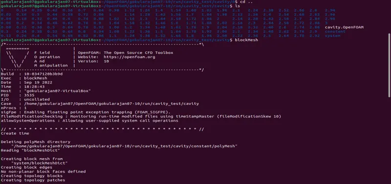
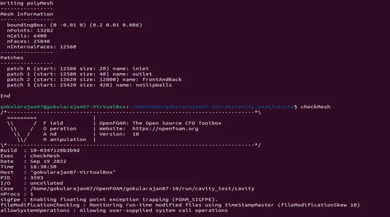
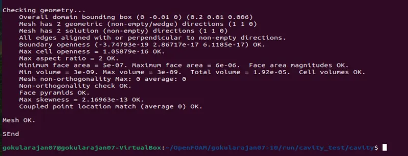
- Use the 'blockMesh' command to generate a mesh.
- Use the 'checkMesh' command to verify the mesh created.
STEP-5: simulate the results

- Execute the Allrun file using the above command to run the simulation or inside the cavity folder use the command icoFoam to run the solver.

- To open the results in ParaView use the command paraFoam.
- use plot over line function to plot the velocity profile graph.
STEP-6: grading factor 0.2
- Edit the simple grading values in the blockMeshDict file as follow,

blockMeshDict file ( Grading factor = 0.2)
/*--------------------------------*- C++ -*----------------------------------*
  =========                 |
  \      /  F ield         | OpenFOAM: The Open Source CFD Toolbox
   \    /   O peration     | Website:  https://openfoam.org
    \  /    A nd           | Version:  10
     \/     M anipulation  |
*---------------------------------------------------------------------------*/
FoamFile
{
    format      ascii;
    class       dictionary;
    object      blockMeshDict;
}
// * * * * * * * * * * * * * * * * * * * * * * * * * * * * * * * * * * * * * //

convertToMeters 0.01;

vertices
(
    //BackFace
    (0 0 0)    //0
    (8 0 0)    //1
    (8 0.5 0)  //2
    (0 0.5 0)  //3
    (8 1 0)    //4
    (0 1 0)    //5
    (20 1 0)   //6
    (20 0.5 0) //7
    (20 0 0)   //8
    (20 -1 0)  //9
    (8 -1 0)   //10

    //FrontFace
    (0 0 0.6)    //11
    (8 0 0.6)    //12
    (8 0.5 0.6)  //13
    (0 0.5 0.6)  //14
    (8 1 0.6)    //15
    (0 1 0.6)    //16
    (20 1 0.6)   //17
    (20 0.5 0.6) //18
    (20 0 0.6)   //19
    (20 -1 0.6)  //20
    (8 -1 0.6)   //21

);

blocks
(
    hex (0 1 2 3 11 12 13 14) (80 10 1) simpleGrading (0.2 5 1)   //block 1
    hex (3 2 4 5 14 13 15 16) (80 10 1) simpleGrading (0.2 0.2 1)   //block 2
    hex (2 7 6 4 13 18 17 15) (120 10 1) simpleGrading (5 0.2 1)  //block 3
    hex (1 8 7 2 12 19 18 13) (120 10 1) simpleGrading (5 5 1)  //block 4
    hex (10 9 8 1 21 20 19 12) (120 20 1) simpleGrading (5 5 1) //block 5
);

edges
(

);

boundary
(
    inlet
    {
        type patch;
        faces
        (
            (0 11 14 3)
            (3 14 16 5)
        );
    }

    outlet
    {
        type patch;
        faces
        (
            (9 8 19 20)
            (8 7 18 19)
            (7 6 17 18)

        );
    }


    frontAndBack
    {
        type empty;
        faces
        (
            (0 3 2 1)
            (11 12 13 14)
            (3 5 4 2)
            (13 15 16 14)
            (2 4 6 7)
            (13 18 17 15)
            (1 2 7 8)
            (12 19 18 13)
            (10 1 8 9)
            (21 20 19 12)
        );
    }

    noSlipWalls
    {
        type wall;
        faces
        (
            (4 5 16 15)
            (4 15 17 6)
            (0 1 12 11)
            (9 20 21 10)
            (1 10 21 12)
        );
    }
);

mergePatchPairs
(

);


// ************************************************************************* //
- Repeat the above steps 4 and 5 for grading factor 0.2 to check the differences in results.
OUTPUTS:
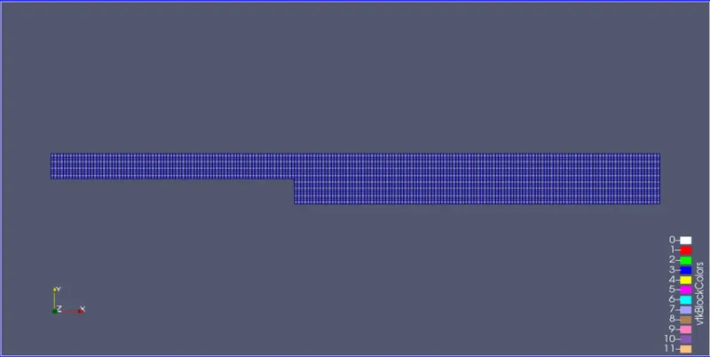
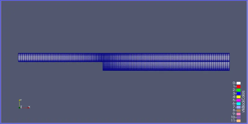
- Block Mesh for grading factor 1.
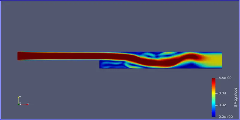
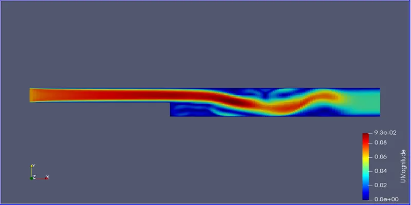
- Final velocity distribution along the domain for grading factor 1.
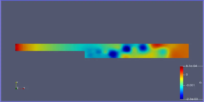
- Final pressure distribution along the domain for grading factor 1.
- Final velocity distribution graph along the domain for grading factor 1. (the velocity profile plotted from the point 0.085m from the inlet.)
Grading factor 0.2:
- Block Mesh for grading factor 0.2.
- Final velocity distribution along the domain for grading factor 0.2.
- Final pressure distribution along the domain for grading factor 0.2.
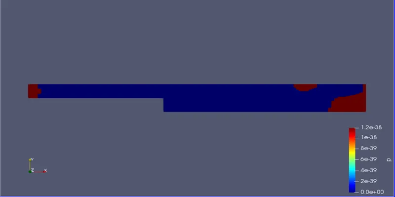
- Final velocity distribution graph along the domain for grading factor 0.2. (the velocity profile plotted from the point 0.085m from the inlet.)
RESULT:
- The plots look similar for grading factors 1 and 0.2.
- But the accurate results are achieved for grading factor 1 as the mesh is uniform throughout the domain.
- But in reality, we cannot apply grading factor 1 for all the problems. As it won't be efficient.
- For complex problems, making the mesh coarse near the walls will help us save simulation time.
- So here, making the mesh coarse near inlet and outlet walls and near no-slip walls made the simulation bit more efficient.