Week 8 - Simulation of a backward facing step in OpenFOAM
Aim :- Simulation of a backward facing step in OpenFOAM.
Objective :- Simulate an incompressible-laminar-viscous flow through the backward facing step geometry. Also perform a transient simulation.
Case 1 - Simulate the flow without using any grading factor (i.e., GF = 1)
Case 2 - Simulate the flow with grading factor of 0.2. The cells should be finer near the walls (includig the step wall).
Theory :-
Backward Facing Step (BFS) is widely known for its application in the studies on internal flows. Flow separation is a common and interesting phenomenon in fluid mechanics with significant effects in practical application. Thus, it has been the focus of intensive study for many years. A standard set of simple geometric configurations including the flow in a pipe with a sudden expansion, the flow in a pipe with an obstruction such as an orifice, the flow over an obstacle in a channel and the flow in a channel with a sudden expansion, has been proposed as representative test cases.
Backward Facing Step is one of the vital flow geometry for investigating separated flows. In this the flow enters from the inlet passes through a constant area duct and exits into another duct having a cross-sectional area larger than the inlet duct. As this occurs, a recirculation zone occurs at the 'step’ of the duct having a larger cross-sectional area. The flow separation is caused due to the sudden changes in the geometry. This creates a zone of re-circulation and a point of flow reattachment. Even though it is a simple and common problem but it has a wide scope, which makes it a building block for a variety of applications. This recirculation depends on the Reynolds number of the flow, size of the step, expansion ratio, aspect ratio (in 3D case), etc.
Mesh specification
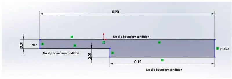
- Number of cells along the x direction (longer dimension) = 200
- Number of cells along with the longer y-direction = 20;
Boundary condition specification
The domain specifications are provided in the following figure.
Geometry Creation:
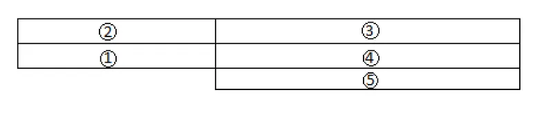
Let us consider creating the geometry using 5 blocks as shown in the figure below,
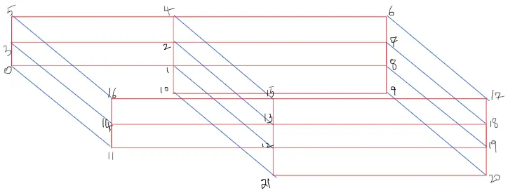
Vertices for each block by referring above figure,
Meshing :-
Meshing is the process in which the continuous geometric space of an object is broken down into very small pieces of shapes to properly define the physical shape of the object. The more detailed a mesh is, the more accurate the CAD model will be, allowing for high fidelity simulations. Meshing, also known as mesh generation, is the process of generating a two-dimensional and three-dimensional grid; it is dividing complex geometries into elements that can be used to discretize a domain. Computers cannot solve simulations on the CAD model’s actual geometry shape as the governing equations cannot be applied to an arbitrary shape. Mesh elements allow governing equations to be solved on predictably shaped and mathematically defined volumes.
Grading Factor - In order to see the desired phenomenon in particular region of interest (Usaully most of the time to capture boundary layers near the wall) the grid size need to be kept small so to achieve this, in OpenFOAM the concept of ‘grading’ is used.
So, Grading factor (GF) is ratio of length of end cell to the start cell.
Vertices and Boundary conditions,
/*--------------------------------*- C++ -*----------------------------------*\
  =========                 |
  \\      /  F ield         | OpenFOAM: The Open Source CFD Toolbox
   \\    /   O peration     | Website:  https://openfoam.org
    \\  /    A nd           | Version:  10
     \\/     M anipulation  |
\*---------------------------------------------------------------------------*/
FoamFile
{
    format      ascii;
    class       dictionary;
    object      blockMeshDict;
}
// * * * * * * * * * * * * * * * * * * * * * * * * * * * * * * * * * * * * * //

convertToMeters 0.01;

vertices
(
    (0 0 0) //0
    (8 0 0) //1
    (8 0.5 0) //2
    (0 0.5 0) //3
    (8 1 0) //4
    (0 1 0) //5
    (20 1 0) //6
    (20 0.5 0) //7
    (20 0 0) //8
    (20 -1 0) //9
    (8 -1 0) //10
    (0 0 0.1) //11
    (8 0 0.1) //12
    (8 0.5 0.1) //13
    (0 0.5 0.1) //14
    (8 1 0.1) //15
    (0 1 0.1) //16
    (20 1 0.1) //17
    (20 0.5 0.1) //18
    (20 0 0.1) //19
    (20 -1 0.1) //20
    (8 -1 0.1) //21
);

blocks
(
    hex (0 1 2 3 11 12 13 14) (80 5 1) simpleGrading (1 1 1)
    hex (3 2 4 5 14 13 15 16) (80 5 1) simpleGrading (1 1 1)
    hex (2 7 6 4 13 18 17 15) (120 5 1) simpleGrading (1 1 1)
    hex (1 8 7 2 12 19 18 13) (120 5 1) simpleGrading (1 1 1)
    hex (10 9 8 1 21 20 19 12) (120 10 1) simpleGrading (1 1 1)
);
edges
(
);
boundary
(
    inlet
    {
        type patch;
        faces
        (
            (0 11 14 3)
            (3 14 16 5)
        );
    }
    outlet
    {

        type patch;
        faces
        (
            (9 8 19 20)
            (8 7 18 19)
            (7 6 17 18)
        );
    }
    fixedwalls
    {

       type wall;
       faces
       (
           (5 16 15 4)
           (0 1 12 11)
           (4 15 17 6)
           (10 9 20 21)
           (10 21 12 1)
        );
    frontAndBack
    {
        type empty;
        faces
        (
            (11 12 13 14)
            (14 13 15 16)
            (13 18 15 17)
            (12 19 18 13)
            (21 20 19 12)
            (0 3 2 1)
            (3 5 4 2)
            (2 4 6 7)
            (1 2 7 8)
            (10 1 8 9)

        );
    }

    }
);
mergePatchPairs
(
);


// ************************************************************************* //
Specifying the boundary conditions as follows : the inlet faces of the geometry is named as inlet and the vertices are specified using right hand rule. Same as to the outlet and other walls. At the end we merge the patches using merge command.
(80 5 1) and (120 5 1) given beside the hex command specifies the number of mesh points along the x-axis and y-axis.
the command specified above will also generate the mesh with a grading factor of 1. 'simpleGrading' command is used here.
suppose we want to change the grading factor along x-axis so the ratio of size of end cell to the size of start cell gives the grading factor for that particular axis. so a grading factor of simpleGrading(0.1 1 1) will provide finer mesh as we move along the x-axis and simpleGrading(10 1 1) will provide coarser mesh as we move along x-axis.
For this case the entries in the controlDict are shown below
/*--------------------------------*- C++ -*----------------------------------*\
  =========                 |
  \\      /  F ield         | OpenFOAM: The Open Source CFD Toolbox
   \\    /   O peration     | Website:  https://openfoam.org
    \\  /    A nd           | Version:  10
     \\/     M anipulation  |
\*---------------------------------------------------------------------------*/
FoamFile
{
    format      ascii;
    class       dictionary;
    location    "system";
    object      controlDict;
}
// * * * * * * * * * * * * * * * * * * * * * * * * * * * * * * * * * * * * * //

application     icoFoam;

startFrom       startTime;

startTime       0;

stopAt          endTime;

endTime         0.2;

deltaT          0.00001;

writeControl    timeStep;

writeInterval   20;

purgeWrite      0;

writeFormat     ascii;

writePrecision  6;

writeCompression off;

timeFormat      general;

timePrecision   6;

runTimeModifiable true;


// ************************************************************************* //
Next we set boundary condtion i.e p and u for our faces we have p file as shown below
/*--------------------------------*- C++ -*----------------------------------*\
  =========                 |
  \\      /  F ield         | OpenFOAM: The Open Source CFD Toolbox
   \\    /   O peration     | Website:  https://openfoam.org
    \\  /    A nd           | Version:  10
     \\/     M anipulation  |
\*---------------------------------------------------------------------------*/
FoamFile
{
    format      ascii;
    class       volScalarField;
    object      p;
}
// * * * * * * * * * * * * * * * * * * * * * * * * * * * * * * * * * * * * * //

dimensions      [0 2 -2 0 0 0 0];

internalField   uniform 0;

boundaryField
{
    inlet
    {
        type            zeroGradient;
    }

    outlet
    {
        type            fixedValue;
        value           uniform 0;

     }

    fixedwalls
    {
        type            zeroGradient;
    }

    frontAndBack
    {
        type            empty;
    }
}

// ************************************************************************* //
The first line specifies the dimensions of the field here kinematic pressure i,e m^2s^-2. the boundary consists of the inlet patch for which its given as zero gradient meaning normal gradient of pressure is zero for inlet face and for the outlet the unifrom value is given and for the frontandback faces its given empty as resprent the the front and back planes of the 2d cases therefore it ste has empty.
we have velocity file, contains
/*--------------------------------*- C++ -*----------------------------------*\
  =========                 |
  \\      /  F ield         | OpenFOAM: The Open Source CFD Toolbox
   \\    /   O peration     | Website:  https://openfoam.org
    \\  /    A nd           | Version:  10
     \\/     M anipulation  |
\*---------------------------------------------------------------------------*/
FoamFile
{
    format      ascii;
    class       volVectorField;
    object      U;
}
// * * * * * * * * * * * * * * * * * * * * * * * * * * * * * * * * * * * * * //

dimensions      [0 1 -1 0 0 0 0];

internalField   uniform (0 0 0);

boundaryField
{
    inlet
    {
        type            fixedValue;
        value           uniform (1 0 0);
    }

    outlet
    {
        type            zeroGradient;
    }

    fixedwalls
    {
        type            noSlip;

    }

    frontAndBack
    {
        type            empty;
    }
}

// ************************************************************************* //
The first line resprents the dimensions for velocity which is m/sec hence m^1 and sec^-1 the internal field is initililased as unifrom zero which is expressed in three compoments i.e unifrom (0 0 0) the inlet wall moves at spped of 1 m/sec in the x direction hence fixed value condtion also but with unifrom(1 0 0) the other faces considred as walls hence unifrom value of ( 0 0 0).
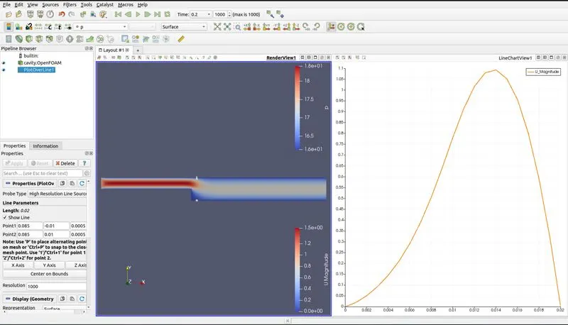
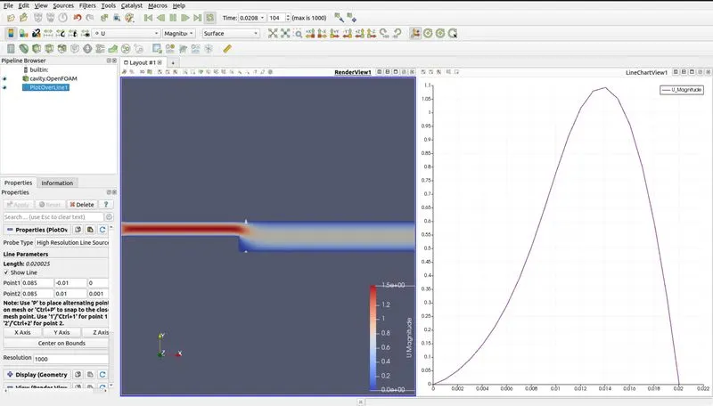
after applying boundary condtion now we run our slover i.e icoFoam and i can be visulaised in the paraFoam
without grading factor
Grading factor 0.2
blocks
(
    hex (0 1 2 3 11 12 13 14) (80 5 1) simpleGrading (0.2 5 1)
    hex (3 2 4 5 14 13 15 16) (80 5 1) simpleGrading (0.2 0.2 1)
    hex (2 7 6 4 13 18 17 15) (120 5 1) simpleGrading (5 0.2 1)
    hex (1 8 7 2 12 19 18 13) (120 5 1) simpleGrading (5 5 1)
    hex (10 9 8 1 21 20 19 12) (120 10 1) simpleGrading (5 5 1)
); 
Grading Factor : It is used to produce the mesh fine or coarse along the particular axis. The regions in geometry where there is abrupt change in the contours or the geometry is complex , there we can produce mesh as fine so that we could capture the results accurately.