Week 8 - Simulation of a backward facing step in OpenFOAM
Simulation of a backward-facing step in OpenFOAM
Aim:-
- Simulate an incompressible-laminar-viscous flow through the backward facing step geometry.
- Perform transient simulation; choose solver based on the described physics of the flow in problem statement.
- Explain simulation process and way of setting up the problem statement in openFOAM and also, explain every changes that have done inside the reference case files obtained from OpenFOAM tutorials.
- Next, preform two case study, firstly, form simulation of the flow without using any grading factor (i.e., GF = 1) . Secondly, simulate the flow with grading factor of 0.2. The cells should be finer near the walls (including the the step wall).
Objective:-
- Open openFoam tutorials and find the the solver to solve incompressible-laminar-viscous flow problem.
- Next step is to copy required file in solver and paste it in OpenFOAM run folder so that the official file of OpenFoam remain untouched.
- Find out block mesh script file to create domain space and provide mesh specification.
- Find ‘controlDict’ file to edit start and end time for simulation.
- In initial folder ‘0’ edit initial parameter for velocity and pressure according to faces of the given domain.
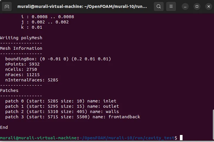
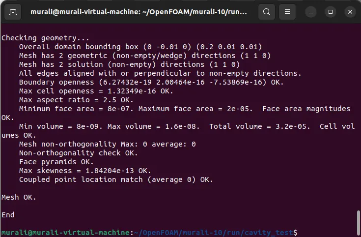
- Use blockMesh command to generate mesh and checkMesh to verify it.
- Open simulation file in paraView and plot the velocity profile at point 0.085m from inlet.
- Repeat above procedure for grading factor 0.2 to check the differences in results.
- Write a detailed report explaining all the command and codes used in project.
Problem Statement:-
simulate an incompressible-laminar-viscous flow through the backward facing step geometry.
perform 2 case studies as described below and compare the results.
Case 1 - Simulate the flow without using any grading factor (i.e., GF = 1)
Case 2 - Simulate the flow with grading factor of 0.2. The cells should be finer near the walls (includig the step wall).
Mesh specification:-
- Number of cells along the x direction (longer dimension) = 200
- Number of cells along the longer y direction = 20;
Boundary condition specification
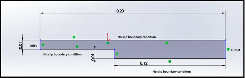
The domain specifications are provided in the following figure.
In order to start the simulation process, First start terminal in Linux Operating system using ctrl+alt+T buttons on key board or right click -> Open Terminal. After starting terminal you will see following window.
1) Now, we have to simulate our problem in openFOAM and we are going to solve our problem using tutorials present in openFOAM, therefore, just type ‘tut’ to open OpenFOAM tutorial directory. And type ‘ls’ to identify what kind of tutorials present inside this directory.
2) We have to solve incopressible flow simulation for this problem so select incompressible directory by typing ‘cd incompressible’ and then again type ls to explore folders in incopressible folders.
3) we can see the solver folders. For this particular solver we need solver for laminar-viscous flow. So here we choose ‘icoFoam’
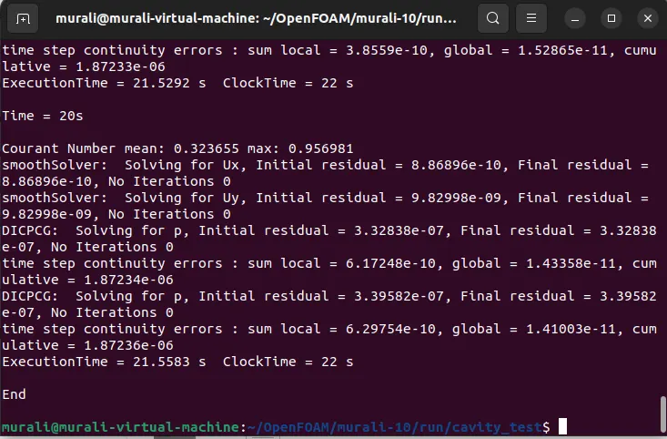
icoFoam is the solver in openFoam which is use as transient solver for incompressible, laminar flow of Newtonian fluids.
(Newtonian fluid is a fluid in which the viscous stress arising from its flow, at every point, are linearly correlated to the local strain rate - the rate of change of its deformation over time. Newtonian fluids are the simplest mathematical models of fluids that account for viscosity.)
Therefore, we will select icoFoam folder by typing ‘cd icoFoam’ and by typing ‘ls’ we explore this folder in terminal.
4) Then we have, again to option, cavity and elbow. They both are part of the icoFoam solver and cavity section use to create required domain and black mesh so select ‘cavity’ folder.
5) In cavity, we are, again, going to see cavity folder, where we have to define our fluid domain and generate block mesh.
But we are not going to make any changes here in tutorial section. First of all, OpenFoam does no let anyone make any changes in their official tutorial and secondly, any changes with their official tutorials my corrupt openFoam. An in a bid to correct it, we may need to reinstall openfoam all over again.
So, we are going to copy this cavity folder using ‘cp -r cavity’ command and paste it in openFoam run folder by typing ‘cp -r cavity $FOAM_RUN/cavity_test’.
And then open run folder by typing ‘cd $FOAM_RUN’. where we can see cavity_test file.
6) Then we can make any changes to the cavity_test file, which will never affect the openFoam official files. Open cavity_test folder. Here, we can provide specification for our block mesh in system folder.
7) then we can get 4 script file system folder and by opening blockMeshDict we can create domain and provide required specification for block mesh. So, open this file by typing ‘gedit blockMeshDict’.
8) Now, make following changes in blockMeshDict script file.
The blockMeshDict file is a script file that contains information regarding all aspects of the geometry.
- Then will make the required changes in the blockMeshDict file that is naming the vertices for and then creating the blocks, in this case, there are 21 vertices and 5 blocks while creating blocks we also need to specify the number of mesh points needed along the x, y, and z-direction and also the simple grading should be done along the boundaries.
- then, we need to assign the boundary conditions here, we need to define all the faces in OpenFOAM refers to patches and giving them type that is the inlet and outlet will be the faces (type patch), for front and back type will be empty faces, for top and bottom which are the boundary conditions in this case type will be wall type and setting up these will constitute a particular boundary, then will save these changes in the blockMeshDict.
- Then, in the velocity and pressure files, we have to give the value of the velocity at the inlet type will be fixed value here we should assign some value as initial velocity and pressure will be zerogradient and at the outlet velocity type will be zerogradient and pressure will be type fixedvalue that value will be uniform 0, then at front and back velocity type empty and pressure, as well as type empty at the no slip boundaries that is top and bottom velocity, will be type noslip and pressure type empty. And in the transportProperties we can change the nu value in order to obtain the lower courant number.
- And in the controlDict file the simulation time and the time step need be assigned in the way that the courant number should be less than 2.
- and then creating the block mesh and then run the simulation using the respective solver after the completion of simulation open the paraview in the paraFoam and plot the velocity profile for the given value.
CODE:
BLOCKMESHDICT :
blockMeshDict: (for Gradient factor of 1)
/*--------------------------------*- C++ -*----------------------------------*\
  =========                 |
  \\      /  F ield         | OpenFOAM: The Open Source CFD Toolbox
   \\    /   O peration     | Website:  https://openfoam.org
    \\  /    A nd           | Version:  10
     \\/     M anipulation  |
\*---------------------------------------------------------------------------*/
FoamFile
{
    format      ascii;
    class       dictionary;
    object      blockMeshDict;
}
// * * * * * * * * * * * * * * * * * * * * * * * * * * * * * * * * * * * * * //

convertToMeters 0.01;

vertices
(
    (0 0 0) //vertex 0
    (8 0 0)  //vertex 1
    (8 0.5 0)  //vertex 2
    (0 0.5 0)  //vertex 3
    (8 1 0)  //vertex 4
    (0 1 0)  //vertex 5
    (20 1 0)  //vertex 6
    (20 0.5 0)  //vertex 7
    (20 0 0)  //vertex 8
    (20 -1 0)  //vertex 9
    (8 -1 0)  //vertex 10
    (0 0 1)  //vertex 11
    (8 0 1)  //vertex 12
    (8 0.5 1)  //vertex 13
    (0 0.5 1)  //vertex 14
    (8 1 1)  //vertex 15
    (0 1 1)  //vertex 16
    (20 1 1)  //vertex 17
    (20 0.5 1)  //vertex 18
    (20 0 1)  //vertex 19
    (20 -1 1)  //vertex 20
    (8 -1 1)  //vertex 21
 );

blocks
(
    hex (0 1 2 3 11 12 13 14) (50 5 1) simpleGrading (1 1 1)
    hex (3 2 4 5 14 13 15 16) (50 5 1) simpleGrading (1 1 1)
    hex (2 7 6 4 13 18 17 15) (150 5 1) simpleGrading (1 1 1)
    hex (1 8 7 2 12 19 18 13) (150 5 1) simpleGrading (1 1 1)
    hex (10 9 8 1 21 20 19 12) (150 5 1) simpleGrading (1 1 1)

);

edges
(
);

boundary
(

    inlet
    {
        type patch;
        faces
        (
            (0 11 14 3)
            (3 14 16 5)

        );
    }
    outlet
    {
        type patch;
        faces
        (
            (9 8 19 20)
            (8 7 18 19)
            (7 6 17 18)
        );
    }
   walls
    {
        type wall;
        faces
        (
            (4 5 16 15)
            (6 4 15 17)
            (0 1 12 11)
            (10 9 20 21)
            (10 21 12 1)

        );
    }
     fromtandback
    {
        type empty;
        faces
        (
            (11 12 13 14)
            (14 13 15 16)
            (13 18 17 15)
            (12 19 18 13)
            (21 20 19 12)
            (0 3 2 1)
            (3 5 4 2)
            (10 1 8 9)
            (1 2 7 8 )
            (2 4 6 7 )

        );
    }


);


mergePatchPairs
(
);
// ************************************************************************* //
With the applied grading factor 0.2
/*--------------------------------*- C++ -*----------------------------------*\
  =========                 |
  \\      /  F ield         | OpenFOAM: The Open Source CFD Toolbox
   \\    /   O peration     | Website:  https://openfoam.org
    \\  /    A nd           | Version:  10
     \\/     M anipulation  |
\*---------------------------------------------------------------------------*/
FoamFile
{
    format      ascii;
    class       dictionary;
    object      blockMeshDict;
}
// * * * * * * * * * * * * * * * * * * * * * * * * * * * * * * * * * * * * * //

convertToMeters 0.01;

vertices
(
    (0 0 0) //vertex 0
    (8 0 0)  //vertex 1
    (8 0.5 0)  //vertex 2
    (0 0.5 0)  //vertex 3
    (8 1 0)  //vertex 4
    (0 1 0)  //vertex 5
    (20 1 0)  //vertex 6
    (20 0.5 0)  //vertex 7
    (20 0 0)  //vertex 8
    (20 -1 0)  //vertex 9
    (8 -1 0)  //vertex 10
    (0 0 1)  //vertex 11
    (8 0 1)  //vertex 12
    (8 0.5 1)  //vertex 13
    (0 0.5 1)  //vertex 14
    (8 1 1)  //vertex 15
    (0 1 1)  //vertex 16
    (20 1 1)  //vertex 17
    (20 0.5 1)  //vertex 18
    (20 0 1)  //vertex 19
    (20 -1 1)  //vertex 20
    (8 -1 1)  //vertex 21
 );

blocks
(
    hex (0 1 2 3 11 12 13 14) (50 5 1) simpleGrading (1 5 1)
    hex (3 2 4 5 14 13 15 16) (50 5 1) simpleGrading (1 0.2 1)
    hex (2 7 6 4 13 18 17 15) (150 5 1) simpleGrading (5 0.2 1)
    hex (1 8 7 2 12 19 18 13) (150 5 1) simpleGrading (5 5 1)
    hex (10 9 8 1 21 20 19 12) (150 5 1) simpleGrading (5 10 1)

);

edges
(
);

boundary
(

    inlet
    {
        type patch;
        faces
        (
            (0 11 14 3)
            (3 14 16 5)

        );
    }
    outlet
    {
        type patch;
        faces
        (
            (9 8 19 20)
            (8 7 18 19)
            (7 6 17 18)
        );
    }
   walls
    {
        type wall;
        faces
        (
            (4 5 16 15)
            (6 4 15 17)
            (0 1 12 11)
            (10 9 20 21)
            (10 21 12 1)

        );
    }
     fromtandback
    {
        type empty;
        faces
        (
            (11 12 13 14)
            (14 13 15 16)
            (13 18 17 15)
            (12 19 18 13)
            (21 20 19 12)
            (0 3 2 1)
            (3 5 4 2)
            (10 1 8 9)
            (1 2 7 8 )
            (2 4 6 7 )

        );
    }


);


mergePatchPairs
(
);
// ************************************************************************* //CONTROLDICT:
The Controldict time steps can be controlled in the controldict file. In this simulation start and end time is provided as 0 and 20. deltaT is assumed to be 0.01.
/*--------------------------------*- C++ -*----------------------------------*\
  =========                 |
  \\      /  F ield         | OpenFOAM: The Open Source CFD Toolbox
   \\    /   O peration     | Website:  https://openfoam.org
    \\  /    A nd           | Version:  10
     \\/     M anipulation  |
\*---------------------------------------------------------------------------*/
FoamFile
{
    format      ascii;
    class       dictionary;
    location    "system";
    object      controlDict;
}
// * * * * * * * * * * * * * * * * * * * * * * * * * * * * * * * * * * * * * //

application     icoFoam;

startFrom       startTime;

startTime       0;

stopAt          endTime;

endTime         20;

deltaT          0.01;

writeControl    timeStep;

writeInterval   20;

purgeWrite      0;

writeFormat     ascii;

writePrecision  6;

writeCompression off;

timeFormat      general;

timePrecision   6;

runTimeModifiable true;


// ************************************************************************* //
PRESSURE FILE:
Initial condition: The initial condition for velocity and pressure can be provided in the p and U file located in the 0 folder.
/*--------------------------------*- C++ -*----------------------------------*\
  =========                 |
  \\      /  F ield         | OpenFOAM: The Open Source CFD Toolbox
   \\    /   O peration     | Website:  https://openfoam.org
    \\  /    A nd           | Version:  10
     \\/     M anipulation  |
\*---------------------------------------------------------------------------*/
FoamFile
{
    format      ascii;
    class       volScalarField;
    object      p;
}
// * * * * * * * * * * * * * * * * * * * * * * * * * * * * * * * * * * * * * //

dimensions      [0 2 -2 0 0 0 0];

internalField   uniform 0;

boundaryField
{
    inlet
    {
        type            zeroGradient;
    }

   outlet
    {
        type            fixedValue;
        value           uniform 0;
    }

    frontandback
    {
        type            empty;
    }

   walls
    {
        type            zeroGradient;
    }
}

// ************************************************************************* //
VELOCITY FILE:
Initial condition: The initial condition for velocity and pressure can be provided in the p and U file located in the 0 folder.
/*--------------------------------*- C++ -*----------------------------------*\
  =========                 |
  \\      /  F ield         | OpenFOAM: The Open Source CFD Toolbox
   \\    /   O peration     | Website:  https://openfoam.org
    \\  /    A nd           | Version:  10
     \\/     M anipulation  |
\*---------------------------------------------------------------------------*/
FoamFile
{
    format      ascii;
    class       volVectorField;
    object      U;
}
// * * * * * * * * * * * * * * * * * * * * * * * * * * * * * * * * * * * * * //

dimensions      [0 1 -1 0 0 0 0];

internalField   uniform (0 0 0);

boundaryField
{
    inlet
    {
        type            fixedValue;
        value           uniform (0.05 0 0);
    }

    walls
    {
        type            noSlip;
    }

    frontandback
    {
        type            empty;
    }
    outlet
    {
        type          zeroGradient;
    }
}

// ************************************************************************* //
PHYSICAL PROPERTIES:
/*--------------------------------*- C++ -*----------------------------------*\
  =========                 |
  \\      /  F ield         | OpenFOAM: The Open Source CFD Toolbox
   \\    /   O peration     | Website:  https://openfoam.org
    \\  /    A nd           | Version:  10
     \\/     M anipulation  |
\*---------------------------------------------------------------------------*/
FoamFile
{
    format      ascii;
    class       dictionary;
    location    "constant";
    object      physicalProperties;
}
// * * * * * * * * * * * * * * * * * * * * * * * * * * * * * * * * * * * * * //

nu              [0 2 -1 0 0 0 0] 1e-5;


// ************************************************************************* //
BLOCKMESH:
CHECKMESH:
ICOFOAM:
GF = 0.2
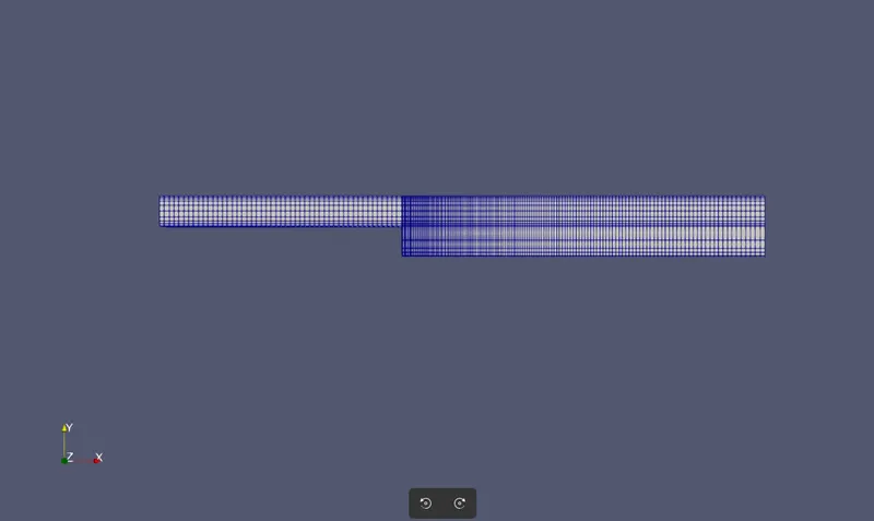
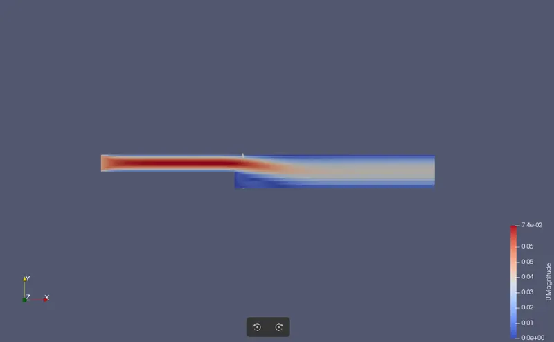
velocity distribution in backward facing step:
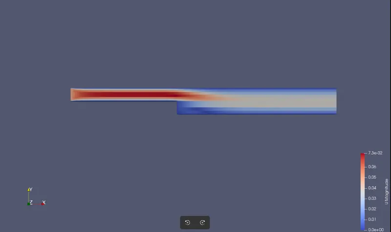
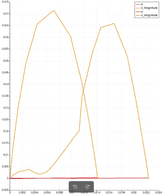
plot of variation of velocity with GF = 0.2 at the walls.( at a distance 0.085m )
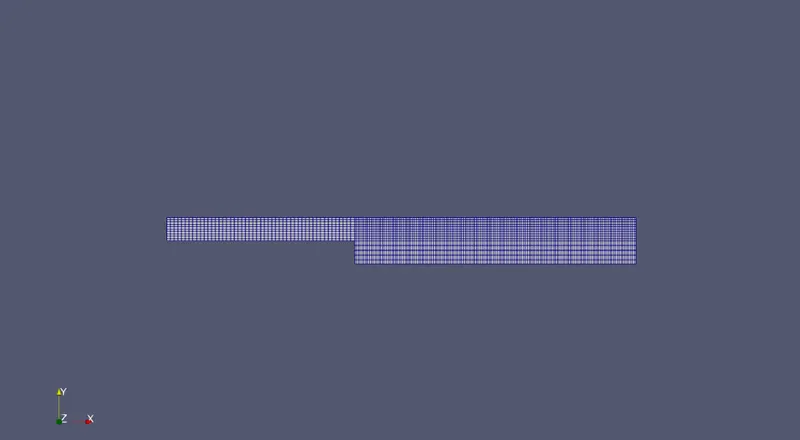
Mesh image GF = 1
velocity distribution in backward facing step:
Plot of variation of velocity: at a distance 0.085m
with GF =1
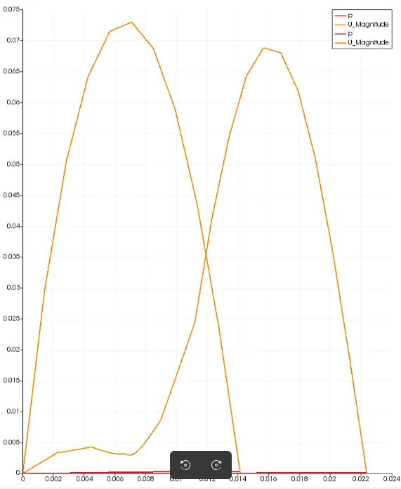
CONCLUSION:
Then, finally we have to conclude from the graph it’s clear that as with the increase in the fine mesh with GF =0.2 the curve is bit smoother to capture the velocity at the specific point whereas for the coarse mesh with GF = 1 the curve is bit short at the peak and hence for capturing more accurate results at the specific point the mesh can be made finer instead of coarse mesh the accuracy of results is more. However the computation time increases with finer mesh.