Week 8 - Simulation of a backward facing step in OpenFOAM
Aim:
- To briefly explain the simulation of an incompressible-laminar-viscous flow through a backward facing step geometry.
- To perform two case studies, one, to do the above simulation without using any grading factor and another, to simulate the above using a grading factor of 0.2, i.e, the cells should be finer at the walls.
Methodology:
- Solver used - Tutorial --> Incompressible --> icofoam(icofoam is used to perform transient simulation for incompressible - laminar - viscous of newtonian fluids)
- A copy of cavity file from the above solver will be used to perform our task
- Build blockmeshes to make a backward facing step geometry by making desired changes in the script of blockMeshDict. Also the number of cells in x and y directions are 200 and 20 respectively
- Edit the controlDict script to change the tolerance and start and end time for simulation
- Edit the initial conditions, i.e, the initial values of velocity and pressure, in the initial folder '0'.
- Use blockMesh command to generate mesh and checkMesh to verify it.
- Use paraview to simulate and plot velocity profile at point 0.085m from inlet.
- perform the above task for both the cases- without grading factor and with a grading factor of 0.2
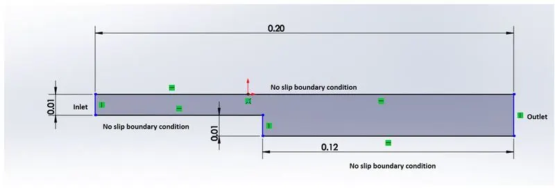
The Domain specifications are specified in the following figure:
yuvaraj@DESKTOP-G8E21TH:/mnt/c/Users/YUVARAJ$ tut
yuvaraj@DESKTOP-G8E21TH:/opt/openfoam9/tutorials$ ls
Allclean  combustion        heatTransfer    resources
Allrun    compressible      incompressible  stressAnalysis
Alltest   discreteMethods   lagrangian
DNS       electromagnetics  mesh
basic     financial         multiphase
yuvaraj@DESKTOP-G8E21TH:/opt/openfoam9/tutorials$ cd incompressible/
yuvaraj@DESKTOP-G8E21TH:/opt/openfoam9/tutorials/incompressible$ ls
SRFPimpleFoam                 icoFoam              porousSimpleFoam
SRFSimpleFoam                 nonNewtonianIcoFoam  shallowWaterFoam
adjointShapeOptimisationFoam  pimpleFoam           simpleFoam
boundaryFoam                  pisoFoam
yuvaraj@DESKTOP-G8E21TH:/opt/openfoam9/tutorials/incompressible$ cd icoFoam/yuvaraj@DEyuvaraj@DEyuvyyyuvaraj@DESKTOP-G8E21TH:/opt/openfoam9/tutorials/incompressible/icoFoam$ ls
cavity  elbow
yuvaraj@DESKTOP-G8E21TH:/opt/openfoam9/tutorials/incompressible/icoFoam$ cd cavity
yuvaraj@DESKTOP-G8E21TH:/opt/openfoam9/tutorials/incompressible/icoFoam/cavity$ ls
Allclean  Allrun  cavity  cavityClipped  cavityGrade
yuvaraj@DESKTOP-G8E21TH:/opt/openfoam9/tutorials/incompressible/icoFoam/cavity$ cp -r cavity $FOAM_RUN/cavity1
yuvaraj@DESKTOP-G8E21TH:/opt/openfoam9/tutorials/incompressible/icoFoam/cavity$ run
yuvaraj@DESKTOP-G8E21TH:~/OpenFOAM/yuvaraj-9/run$ ls
cavity  cavity1  flange
yuvaraj@DESKTOP-G8E21TH:~/OpenFOAM/yuvaraj-9/run$ cd cavity1
yuvaraj@DESKTOP-G8E21TH:~/OpenFOAM/yuvaraj-9/run/cavity1$ ls
0  constant  system
yuvaraj@DESKTOP-G8E21TH:~/OpenFOAM/yuvaraj-9/run/cavity1$ cd system/
yuvaraj@DESKTOP-G8E21TH:~/OpenFOAM/yuvaraj-9/run/cavity1/system$ ls
blockMeshDict  controlDict  fvSchemes  fvSolution
yuvaraj@DESKTOP-G8E21TH:~/OpenFOAM/yuvaraj-9/run/cavity1/system$ notepad.exe blockMeshDict
The above code shows the execution of the following tasks.
To begin with, we open the Windows Terminal to use Ubuntu's Terminal. Then we open Tutorial by using the command 'tut'. As the flow is incompressible-laminar-viscous flow, we will be choosing the incompressible file , where we can find the icoFoam file, which is used to similuate incompressible- laminar-viscous flows,to execute this, we use the following commands : 'cd incompressible/' & then,'cd icoFoam/. In icoFoam, we will be using the cavity file that is present inside the cavity file in icoFoam, we find it by using the command, 'cd cavity/'. As by default, we cant and shouldnt be editing a tutorial file within the tutorial, we will be making a copy of it and paste it in FOAM_RUN and rename it as cavity1, to execute this, we use the command,'cp -r cavity $FOAM_RUN/cavity1'. Now, to access this copied file, we use the command,'cd $FOAM_RUN'/ just 'run', then,'cd cavity1'. Now to edit the create blockmeshes, we open the blockMeshDict script file in the system file of cavity1 file,to execte this the following set of commands are used, 'cd system/' then, 'notepade.exe blockMeshDict', this opens the script file in a notepade and we will be making desired changes in it as follows
/*--------------------------------*- C++ -*----------------------------------*\
  =========                 |
  \\      /  F ield         | OpenFOAM: The Open Source CFD Toolbox
   \\    /   O peration     | Website:  https://openfoam.org
    \\  /    A nd           | Version:  9
     \\/     M anipulation  |
\*---------------------------------------------------------------------------*/
FoamFile
{
    format      ascii;
    class       dictionary;
    object      blockMeshDict;
}
// * * * * * * * * * * * * * * * * * * * * * * * * * * * * * * * * * * * * * //

convertToMeters 0.01;

vertices
(
    (0 0 0) //0
    (8 0 0) //1
    (8 0.5 0) //2
    (0 0.5 0) //3
    (8 1 0) //4
    (0 1 0) //5
    (20 1 0) //6
    (20 0.5 0) //7
    (20 0 0) //8
    (20 -1 0) //9
    (8 -1 0) //10
    (0 0 0.1) //11
    (8 0 0.1) //12
    (8 0.5 0.1) //13
    (0 0.5 0.1) //14
    (8 1 0.1) //15
    (0 1 0.1) //16
    (20 1 0.1) //17
    (20 0.5 0.1) //18
    (20 0 0.1) //19
    (20 -1 0.1) //20
    (8 -1 0.1) //21
);

blocks
(
    hex (0 1 2 3 11 12 13 14) (80 5 1) simpleGrading (1 1 1)
    hex (3 2 4 5 14 13 15 16) (80 5 1) simpleGrading (1 1 1)
    hex (2 7 6 4 13 18 17 15) (120 5 1) simpleGrading (1 1 1)
    hex (1 8 7 2 12 19 18 13) (120 5 1) simpleGrading (1 1 1)
    hex (10 9 8 1 21 20 19 12) (120 10 1) simpleGrading (1 1 1)
);

edges
(
);

boundary
(
    inlet
    {
       type patch;
       faces
       (
         (0 11 14 3)
         (3 14 16 5)
       );
    }

    outlet
    {
       type patch;
       faces
       (
         (9 8 19 20)
         (8 7 18 19)
         (7 6 17 18)
       );
    }

    fixedWalls
    {
        type wall;
        faces
        (
            (6 4 15 17)
            (4 5 16 15)
            (10 21 12 1)
            (12 11 0 1)
            (20 21 10 9)
        );
    }

    frontAndBack
    {
        type empty;
        faces
        (
            (0 3 2 1)
            (3 5 4 2)
            (2 4 6 7)
            (1 2 7 8)
            (10 1 8 9)
            (11 12 13 14)
            (14 13 15 16)
            (13 18 17 15)
            (12 19 18 13)
            (21 20 19 12)
        );
    }
);

mergePatchPairs
(
);

// ************************************************************************* //
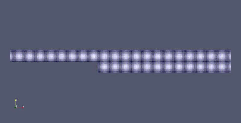
The above changes in the blockMeshDict file in the working file - cavity1, creates our desired blockmeshes to work on. The meshes are defined based on the given mesh specifications and without any grading factor. Then after this, we open the controlDict script file by using the command-'notepad.exe controlDict'.
/*--------------------------------*- C++ -*----------------------------------*\
  =========                 |
  \\      /  F ield         | OpenFOAM: The Open Source CFD Toolbox
   \\    /   O peration     | Website:  https://openfoam.org
    \\  /    A nd           | Version:  9
     \\/     M anipulation  |
\*---------------------------------------------------------------------------*/
FoamFile
{
    format      ascii;
    class       dictionary;
    location    "system";
    object      controlDict;
}
// * * * * * * * * * * * * * * * * * * * * * * * * * * * * * * * * * * * * * //

application     icoFoam;

startFrom       startTime;

startTime       0;

stopAt          endTime;

endTime         0.05;

deltaT          0.0001;

writeControl    timeStep;

writeInterval   20;

purgeWrite      0;

writeFormat     ascii;

writePrecision  6;

writeCompression off;

timeFormat      general;

timePrecision   6;

runTimeModifiable true;


// ************************************************************************* //
Here, the time step is reduced to 1e-4 and the start and end time is set to 0 and 0.5 respectively.
Now, we edit the initial and boundary conditions in the initial file, to execute this, the following commands are used
yuvaraj@DESKTOP-G8E21TH:~/OpenFOAM/yuvaraj-9/run/cavity1/system$ cd ..
yuvaraj@DESKTOP-G8E21TH:~/OpenFOAM/yuvaraj-9/run/cavity1$ cd 0
yuvaraj@DESKTOP-G8E21TH:~/OpenFOAM/yuvaraj-9/run/cavity1/0$ ls
U  p
yuvaraj@DESKTOP-G8E21TH:~/OpenFOAM/yuvaraj-9/run/cavity1/0$ notepad.exe U
yuvaraj@DESKTOP-G8E21TH:~/OpenFOAM/yuvaraj-9/run/cavity1/0$ notepad.exe p
Initial setting for velocity:
/*--------------------------------*- C++ -*----------------------------------*\
  =========                 |
  \\      /  F ield         | OpenFOAM: The Open Source CFD Toolbox
   \\    /   O peration     | Website:  https://openfoam.org
    \\  /    A nd           | Version:  9
     \\/     M anipulation  |
\*---------------------------------------------------------------------------*/
FoamFile
{
    format      ascii;
    class       volVectorField;
    object      U;
}
// * * * * * * * * * * * * * * * * * * * * * * * * * * * * * * * * * * * * * //

dimensions      [0 1 -1 0 0 0 0];

internalField   uniform (0 0 0);


boundaryField
{
    inlet
    {
        type            fixedValue;
        value           uniform (1 0 0);
    }

    outlet
    {
        type            zeroGradient;
    }

    fixedWalls
    {
        type            noSlip;
    }

    frontAndBack
    {
        type            empty;
    }
}

// ************************************************************************* //
Initial settings for pressue:
/*--------------------------------*- C++ -*----------------------------------*\
  =========                 |
  \\      /  F ield         | OpenFOAM: The Open Source CFD Toolbox
   \\    /   O peration     | Website:  https://openfoam.org
    \\  /    A nd           | Version:  9
     \\/     M anipulation  |
\*---------------------------------------------------------------------------*/
FoamFile
{
    format      ascii;
    class       volScalarField;
    object      p;
}
// * * * * * * * * * * * * * * * * * * * * * * * * * * * * * * * * * * * * * //

dimensions      [0 2 -2 0 0 0 0];

internalField   uniform 0;

boundaryField
{
    inlet
    {
        type            zeroGradient;
    }
    outlet
    {
        type            fixedValue;
        value           uniform 0;
    }

    fixedWalls
    {
        type            zeroGradient;
    }

    frontAndBack
    {
        type            empty;
    }
}

// ************************************************************************* //
Once these are edited accordingly, we are all set to simulate this mesh, we then use the following commands : 'blockMesh' and 'icoFoam', then to view the mesh and the flow simulation, we use the command 'paraviewWindows', which opens paraview.
We get the following results in the paraview:
BlockMesh without grading factor:
Pressure distribution :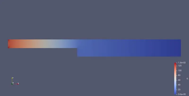
velocity distribution:
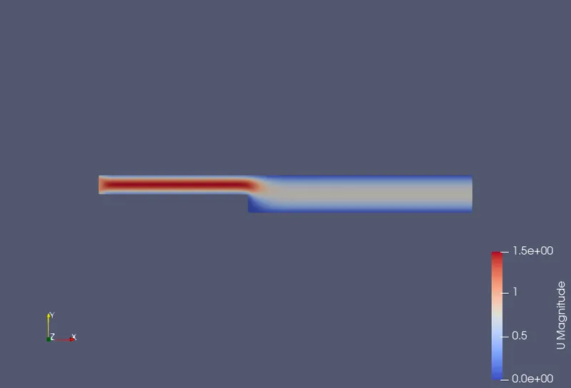
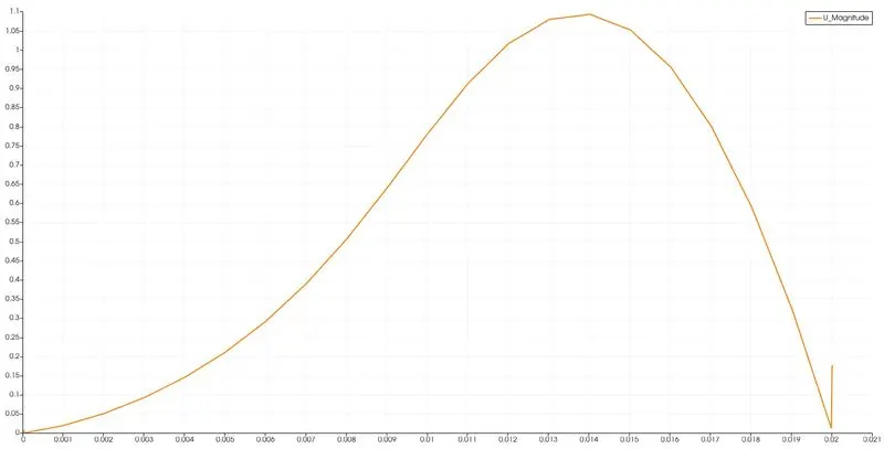
velocity profile(at x=0.085):
Now to simulate the same flow over a backward facing step with a grading factor of 0.2 near the walls, we modify the blocks part in the blockMeshDict file in the systems file as follows:
blocks
(
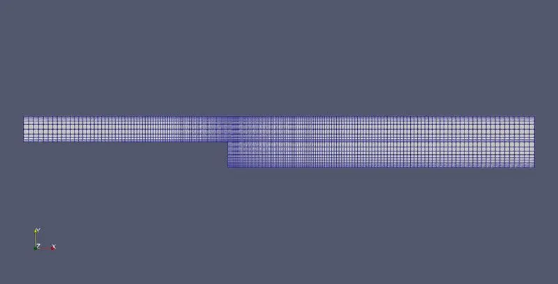
    hex (0 1 2 3 11 12 13 14) (80 5 1) simpleGrading (0.2 5 1)
    hex (3 2 4 5 14 13 15 16) (80 5 1) simpleGrading (0.2 0.2 1)
    hex (2 7 6 4 13 18 17 15) (120 5 1) simpleGrading (5 0.2 1)
    hex (1 8 7 2 12 19 18 13) (120 5 1) simpleGrading (5 5 1)
    hex (10 9 8 1 21 20 19 12) (120 10 1) simpleGrading (5 5 1)
);
This gives the following results:
BlockMesh :
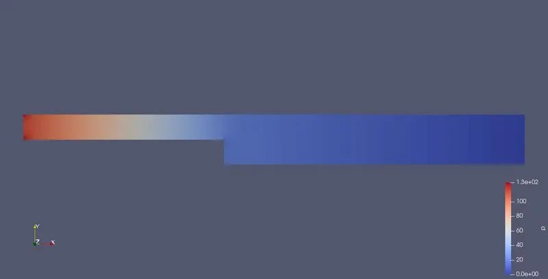
Pressure distribution:
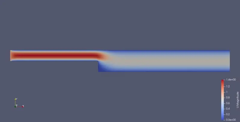
velocity distribution:
velocity profile( at x=0.085):
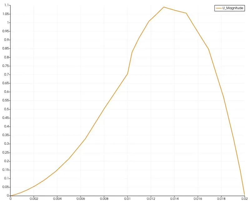
Conclusion:
- On comparing both the cases, we can see that the graph obtained without using any grading factor is comparitively smoother than that with a grading factor of 0.2. But that doesnt mean that the former is accurate. The mesh is fine at the step wall along the x axis, but is quite coarse along the y axis, this makes the graph in the latter case not smooth.
- One should use finer mesh near the point of interests, its a popular fact that in CFD fluid analysis, there will large variations near the walls. So, to get effective and relaible results, one should use the grading feature to make the mesh finer at the desired points.
- It is also not advisable not to use a large number of fine elements, as it may take up a lot of computational time and shall also demand more computational memory.
- So, a knowledge about when and where to use the grading factor is important to get a more reliable result.