Week 8 - Simulation of a backward facing step in OpenFOAM
Problem at hand:
simulate an incompressible-laminar-viscous flow through the backward facing step geometry.
The Geometry specified is:
Mesh specification
- Number of cells along the x direction (longer dimension) = 200
- Number of cells along the longer y direction = 20;
After that, you will perform 2 case studies as described below and compare the results.
Case 1 - Simulate the flow without using any grading factor (i.e., GF = 1)
Case 2 - Simulate the flow with grading factor of 0.2. The cells should be finer near the walls (includig the step wall).
You can use the following mesh parameters but you can feel free to modify these values.
Desired output
- Measure the velocity profile at 0.085 m from the inlet of the geometry for both case studies and compare. You can use the plot over line tool for this.
- Explain why Grading/Growth factor is essential for meshing.
Geometry for block meshing
For the creation of the domain the following blocks are created and the numering scheme mentioned in the figure is used:
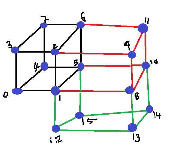
There are three block which are created and the numbering is used as mentioned in the image.
The first thing to do is to create an copy of the files in another directory and this can be done by the following command;
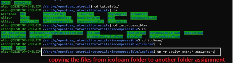
The files in this directory can be edited for the problem at hand.
There are three files which are needed to be edited, They are:
- Zero file
- Constant
- System
ControlDict File: in this file we create the vertices, edges, boundaries hard programmed. In order to create the block more info can be obtained from the following website: https://www.openfoam.com/documentation/user-guide/4-mesh-generation-and-conversion/4.3-mesh-generation-with-the-blockmesh-utility
Important point:
Always maintain the consistency in the numbering scheme and orientation scheme while hard programming for the block mesh. The command used to edit he control dict file is:

gedit blockmeshdict is the command which opens the file to edit the vertices and other geometric data required. Uopn running this we obtain the following file in editable format:
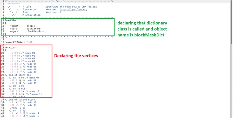
The complete file is as follows:
/*--------------------------------*- C++ -*----------------------------------*\
  =========                 |
  \\      /  F ield         | OpenFOAM: The Open Source CFD Toolbox
   \\    /   O peration     | Website:  https://openfoam.org
    \\  /    A nd           | Version:  9
     \\/     M anipulation  |
\*---------------------------------------------------------------------------*/
FoamFile
{
    format      ascii;
    class       dictionary;
    object      blockMeshDict;
}
// * * * * * * * * * * * * * * * * * * * * * * * * * * * * * * * * * * * * * //

convertToMeters 0.01;

vertices
(
    (0 0 0) // node 00
    (8 0 0) // node 01
    (8 1 0) // node 02
    (0 1 0) // node 03
    (0 0 0.5)// node 04
    (8 0 0.5)// node 05
    (8 1 0.5)// node 06
    (0 1 0.5)// node 07
// end of block one
   // (8  0 0) // node 07
    (20 0 0) // node 08
    (20 1 0) // node 09
   // (8  1 0)
   // (8  0 0.5)
    (20 0 0.5) // node 10
    (20 1 0.5) //// node 11
   // (8  1 0.5)
// end of second block
    (8  -1 0)// node 12
    (20 -1 0)// node 13
    //(20  0 0)
   // (8   0 0)
    (8  -1 0.5)// node 14
    (20 -1 0.5)// node 15
   // (20  0 0.5)
   // (8   0 0.5)
// end of Third block
);

blocks
(
    //hex (0 1 2 3 4 5 6 7)      (80  10 1)  simpleGrading (1 1 1) // block one
   // hex (1 8 9 2 5 10 11 6)    (120 10 1)  simpleGrading (1 1 1) //block two
   // hex (12 13 8 1 14 15 10 5) (120 10 1)  simpleGrading (1 1 1) // block three

    hex (0 1 2 3 4 5 6 7)      (120  20 1)  simpleGrading (1 1 1) // block one
    hex (1 8 9 2 5 10 11 6)    (120  20 1)  simpleGrading (1 1 1) //block two
    hex (12 13 8 1 14 15 10 5) (120  20 1)  simpleGrading (1 1 1) // block three
);

edges
(
);

boundary
(
    Inlet
    {
        type patch;
        faces
        (
            (0 3 7 4) // done
        );
    }
    fixedWalls
    {
        type wall;
        faces
        (
            (3 2 6 7)
            (0 4 5 1)
            (2 9 11 6)
            (12 14 15 13)
            (1 5 12 14)  //done
        );
    }
    frontAndBack
    {
        type empty;
        faces
        (
            (0 1 2 3)
            (4 7 6 5)
            (1 8 9 2)
            (5 6 11 10)
            (12 13 8 1)
            (14 5 10 15)
        );
    }

    Outlet
    {
        type patch;
        faces
        (
            (8 10 11 9)
            (13 15 10 8) // done
        );
    }
);

mergePatchPairs
(
);

// ************************************************************************* //// node 07
For more info refer to the open foam manual:
control dict file
The next thing we need to modify is the control dict file. It can be edited by using the following command
'
Once the file opens the following things can be edited:
- intiial time of simulation
- Final time of simulation (here the time of simultion is 0.5 s)
- The update interval (20 iterations)
- delta t is evaluated to be 0.0005
The file looks like this:
/*--------------------------------*- C++ -*----------------------------------*\
  =========                 |
  \\      /  F ield         | OpenFOAM: The Open Source CFD Toolbox
   \\    /   O peration     | Website:  https://openfoam.org
    \\  /    A nd           | Version:  9
     \\/     M anipulation  |
\*---------------------------------------------------------------------------*/
FoamFile
{
    format      ascii;
    class       dictionary;
    location    "system";
    object      controlDict;
}
// * * * * * * * * * * * * * * * * * * * * * * * * * * * * * * * * * * * * * //

application     icoFoam;

startFrom       startTime;

startTime       0;

stopAt          endTime;

endTime         0.5;

deltaT          0.0005;

writeControl    timeStep;

writeInterval   20;

purgeWrite      0;

writeFormat     ascii;

writePrecision  6;

writeCompression off;

timeFormat      general;

timePrecision   6;

runTimeModifiable true;


// ************************************************************************* //
Zero file
There are two files to be updated here in the boundary conditions:
- U file
- P file
The one important type of boundary we need to consider here while performing an 2d analysis is "Empty"
The P - File
/*--------------------------------*- C++ -*----------------------------------*\
  =========                 |
  \\      /  F ield         | OpenFOAM: The Open Source CFD Toolbox
   \\    /   O peration     | Website:  https://openfoam.org
    \\  /    A nd           | Version:  9
     \\/     M anipulation  |
\*---------------------------------------------------------------------------*/
FoamFile
{
    format      ascii;
    class       volScalarField;
    object      p;
}
// * * * * * * * * * * * * * * * * * * * * * * * * * * * * * * * * * * * * * //

dimensions      [0 2 -2 0 0 0 0];

internalField   uniform 0;

boundaryField
{

    Inlet
    {
        type            zeroGradient;
    }

    fixedWalls
    {
        type            zeroGradient;
    }

    frontAndBack
    {
        type            empty;
    }

    Outlet
    {
        type            fixedValue;
        value           uniform 0;
    }

}


// ************************************************************************* //
The U-File ;
/*--------------------------------*- C++ -*----------------------------------*\
  =========                 |
  \\      /  F ield         | OpenFOAM: The Open Source CFD Toolbox
   \\    /   O peration     | Website:  https://openfoam.org
    \\  /    A nd           | Version:  9
     \\/     M anipulation  |
\*---------------------------------------------------------------------------*/
FoamFile
{
    format      ascii;
    class       volVectorField;
    object      U;
}
// * * * * * * * * * * * * * * * * * * * * * * * * * * * * * * * * * * * * * //

dimensions      [0 1 -1 0 0 0 0];

internalField   uniform (0 0 0);

boundaryField
{
    Inlet
    {
        type            fixedValue;
        value           uniform (1 0 0);
    }

    fixedWalls
    {
        type            noSlip;
    }

    frontAndBack
    {
        type            empty;
    }

    Outlet
    {
        type            zeroGradient;
    }


}

// ************************************************************************* //
to create the mesh file we need to run the following command:

This create an folder with the name polymesh and stores all the data required to reconstruct the geometry
In order to start the simulation the following command is used :
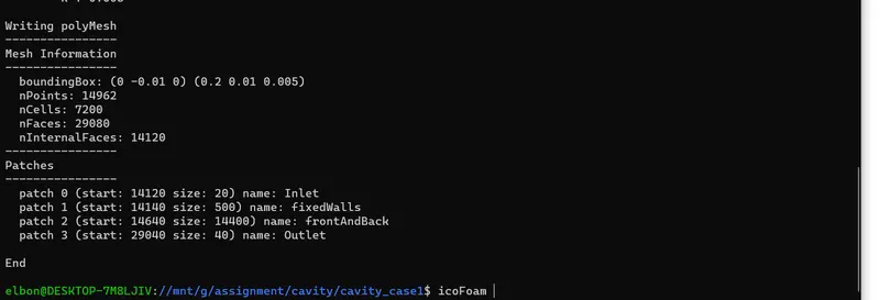
icoFoam is the command which runs the simulation and the to view the results the paraFoam command is used.
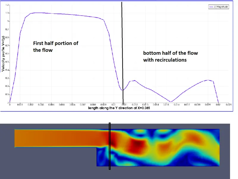
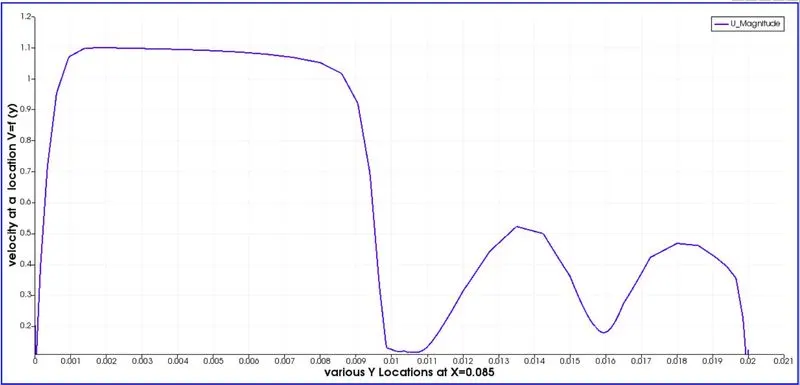
we can see that there is circulation zone at the step and hence in the velocity profile due to re circulation, there is reduction in the velocity at the bottom half section comapared to the top half section.
The second statement was to stretch the mesh using the Grading factor:
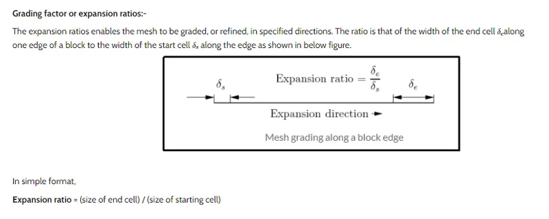 Ref: Open Foam
The following changes are made to the blockmesh dict file:
/*--------------------------------*- C++ -*----------------------------------*\
  =========                 |
  \\      /  F ield         | OpenFOAM: The Open Source CFD Toolbox
   \\    /   O peration     | Website:  https://openfoam.org
    \\  /    A nd           | Version:  9
     \\/     M anipulation  |
\*---------------------------------------------------------------------------*/
FoamFile
{
    format      ascii;
    class       dictionary;
    object      blockMeshDict;
}
// * * * * * * * * * * * * * * * * * * * * * * * * * * * * * * * * * * * * * //

convertToMeters 0.01;

vertices
(
    (0 0 0) // node 00
    (8 0 0) // node 01
    (8 1 0) // node 02
    (0 1 0) // node 03
    (0 0 0.5)// node 04
    (8 0 0.5)// node 05
    (8 1 0.5)// node 06
    (0 1 0.5)// node 07
// end of block one
   // (8  0 0) // node 07
    (20 0 0) // node 08
    (20 1 0) // node 09
   // (8  1 0)
   // (8  0 0.5)
    (20 0 0.5) // node 10
    (20 1 0.5) //// node 11
   // (8  1 0.5)
// end of second block
    (8  -1 0)// node 12
    (20 -1 0)// node 13
    //(20  0 0)
   // (8   0 0)
    (8  -1 0.5)// node 14
    (20 -1 0.5)// node 15
   // (20  0 0.5)
   // (8   0 0.5)
// end of Third block
);

blocks
(
    hex (0 1 2 3 4 5 6 7)      (120  20 1)
    simpleGrading
    (
        0.2                  // x-direction expansion ratio
        (
            (0.2 0.3 4)    // 20% y-dir, 30% cells, expansion = 4
            (0.6 0.4 1)    // 60% y-dir, 40% cells, expansion = 1
            (0.2 0.3 0.25) // 20% y-dir, 30% cells, expansion = 0.25 (1/4)
        )
        1                  // z-direction expansion ratio
    )
    // block one


    hex (1 8 9 2 5 10 11 6)    (120 20 1)
    simpleGrading
    (
        5                  // x-direction expansion ratio
        (
            (0.2 0.3 4)    // 20% y-dir, 30% cells, expansion = 4
            (0.6 0.4 1)    // 60% y-dir, 40% cells, expansion = 1
            (0.2 0.3 0.25) // 20% y-dir, 30% cells, expansion = 0.25 (1/4)
        )
        1                  // z-direction expansion ratio
    )
    // block one

   //block two
    hex (12 13 8 1 14 15 10 5) (120 20 1)
    simpleGrading
    (
        5                  // x-direction expansion ratio
        (
            (0.2 0.3 4)    // 20% y-dir, 30% cells, expansion = 4
            (0.6 0.4 1)    // 60% y-dir, 40% cells, expansion = 1
            (0.2 0.3 0.25) // 20% y-dir, 30% cells, expansion = 0.25 (1/4)
        )
        1                  // z-direction expansion ratio
    )
    // block one
);


edges
(
);

boundary
(
    Inlet
    {
        type patch;
        faces
        (
            (0 3 7 4) // done
        );
    }
    fixedWalls
    {
        type wall;
        faces
        (
            (3 2 6 7)
            (0 4 5 1)
            (2 9 11 6)
            (12 14 15 13)
            (1 5 12 14)  //done
        );
    }
    frontAndBack
    {
        type empty;
        faces
        (
            (0 1 2 3)
            (4 7 6 5)
            (1 8 9 2)
            (5 6 11 10)
            (12 13 8 1)
            (14 5 10 15)
        );
    }

    Outlet
    {
        type patch;
        faces
        (
            (8 10 11 9)
            (13 15 10 8) // done
        );
    }
);

mergePatchPairs
(
);

// ************************************************************************* //// node 07 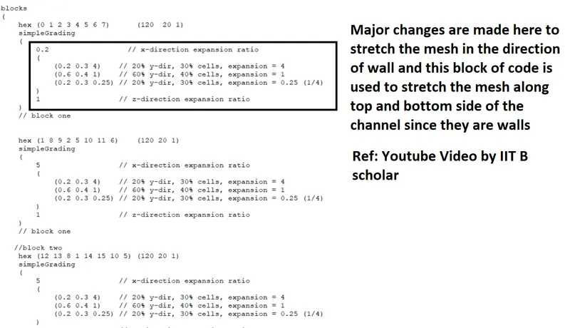
Re running the simulation we have the following results:
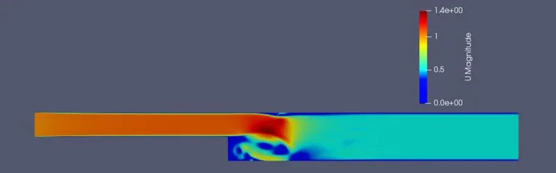
The important factor i.e. stretching the mesh creates a kind of accuracy in capturing the data of velocity and other variables:
the compariosn plot for
- case 1-->Expansion ration 1
- case 2--> expansion ratio varying
The velocity plot is :
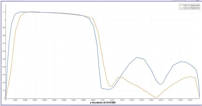
We see that near the wall at 0.085 location the velocity magnitude is more detailed, when comapred to the case 1. The trend is same but the accuracy has increased.
Another things we can conclude that ICOFOAM solver doesnt capture the viscous and turbulent effects and hence the same problem should be run with the other solver to do a bench marking test,