Week 8 - Simulation of a backward facing step in OpenFOAM
Assignment : Flow over backward step
Tutorial : incompressible >> cavity >> cavity
Solver : icoFoam
Meshing : blockMesh
General Steps:
1. Copy the tutorial file into run folder by command: cp -r cavity/ $FOAM_RUN/backward_step
2. Acess the system folder inside backward_step folder by command: cd system/
3. Open blockMeshDict file using notepad by command: notepad.exe blockMeshDict
4. Edit the points in blockMeshDict folder. There are total 22 points indexed from 0 to 21. The co-ordinate of each point confers to local co-ordinate system.
5. Create 5 blocks which represent the 5 sections of our geometry. Use the points in "hex" command line. Define type of grading as well number of divisions along (x y z).
6. Define the boundary faces in the blockMeshDict file. Use the points with right hand thumb rule. Specift type of boundary. The inlet and outlet boundaries are "patch" type. The walls are of "noSlip" boundary condition. The front and back are "empty"
7. Save the blockMeshDict file without changing the name.
8. Go back using cd .. Open the input conditions file from 0 folder. Use command line: cd 0/
9. Open U file: notepad.exe U
10. Modify the boundaries in U file. For inlet, we have fixed value type boundary with value 1m/s. For outlet we have zero gradient type boundary.
11. Save the U file. and open p file. Make suitable changes in boudary conditions. Inlet is zero gradient type. Outlet is fixed value type with value 1 (referes to atmospheric). Save the p file.
12. Go to system folder. Open controlDict file. (notepad.exe controlDict). Check the starting time, ending time, time step.
13. Go back to main folder. Now run the blockMesh command in terminal. After mesh is generated, chech it in paraview.
14. Run icoFoam command in terminal. After the solution is completed, check it in paraview.
Note: The timestep value is changed to 0.0005 sec. This is done to avoid the error caued by CFL number value. The number of cells in y direction is 10 from x=0 to x=0.08 and the number of cells in y direction is 20 from x=0.08 to x=0.2. This is done to avoid CFL number limitation.
Case 1: GF=1
i) Mesh
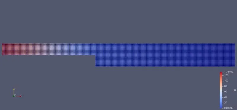
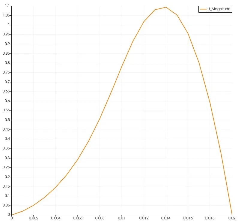
ii) velocity at x=0.85
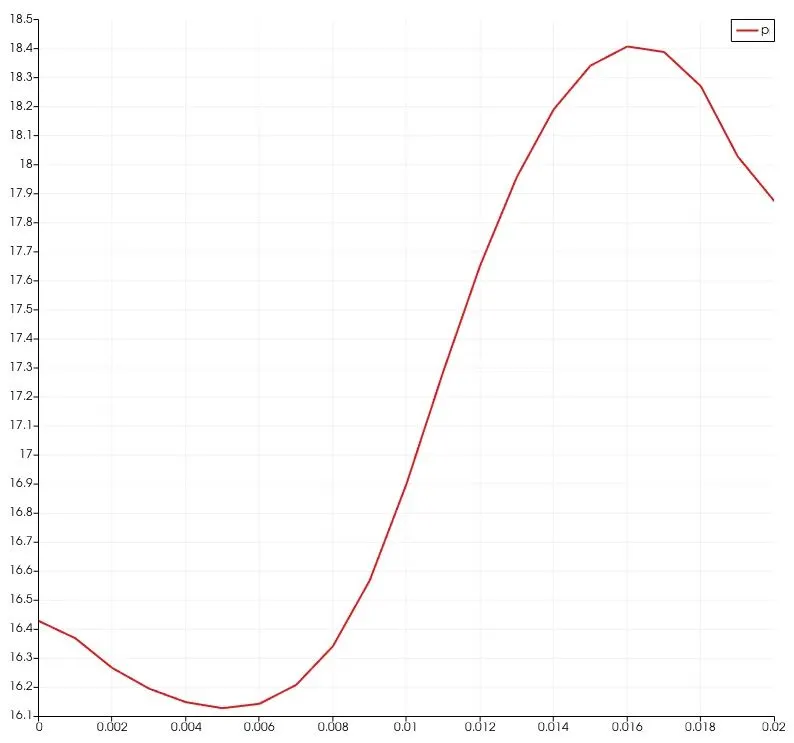
iii) pressure at x=0.85
code: blockMeshDict
scale   0.1;

vertices
(
    (0 0 0)             //0
    (0.8 0 0)           //1
    (0.8 0.05 0)        //2
    (0 0.05 0)          //3
    (0.8 0.1 0)         //4
    (0 0.1 0)           //5
    (2 0.1 0)           //6
    (2 0.05 0)          //7
    (2 0 0)             //8
    (2 -0.1 0)          //9
    (0.8 -0.1 0)        //10
    (0 0 0.1)           //11
    (0.8 0 0.1)         //12
    (0.8 0.05 0.1)      //13
    (0 0.05 0.1)        //14
    (0.8 0.1 0.1)       //15
    (0 0.1 0.1)         //16
    (2 0.1 0.1)         //17
    (2 0.05 0.1)        //18
    (2 0 0.1)           //19
    (2 -0.1 0.1)        //20
    (0.8 -0.1 0.1)      //21

);

blocks
(
    hex (0 1 2 3 11 12 13 14) (80 5 1) simpleGrading (1 1 1)       // block 0
    hex (3 2 4 5 14 13 15 16) (80 5 1) simpleGrading (1 1 1)       // block 1
    hex (2 7 6 4 13 18 17 15) (120 5 1) simpleGrading (1 1 1)      // block 2
    hex (1 8 7 2 12 19 18 13) (120 5 1) simpleGrading (1 1 1)      // block 3
    hex (10 9 8 1 21 20 19 12) (120 10 1) simpleGrading (1 1 1)     // block 4

);

edges
(
);

boundary
(
    inletFace
    {
        type patch;
        faces
        (
            (5 3 14 16)
            (3 0 11 14)
        );
    }
    outletFace
    {
        type patch;
        faces
        (
            (6 17 18 7)
            (7 18 19 8)
            (8 19 20 9)
        );
    }
    fixedWalls
    {
        type wall;
        faces
        (
            (4 5 16 15)
            (0 1 12 11)
            (6 4 15 17)
	    (10 9 20 21)
	    (1 10 21 12)
        );
    }
    frontAndBack
    {
        type empty;
        faces
        (
            (15 16 14 13)
            (13 14 11 12)
	    (17 15 13 18)
	    (18 13 12 19)
	    (19 12 21 20)
            (5 4 2 3)
	    (3 2 1 0)
	    (4 6 7 2)
	    (2 7 8 1)
	    (1 8 9 10)
        );
    }
);

mergePatchPairs
(
);
code: U
dimensions      [0 1 -1 0 0 0 0];

internalField   uniform (0 0 0);

boundaryField
{
    inletFace
    {
        type            fixedValue;
        value           uniform (1 0 0);
    }

    outletFace
    {
        type zeroGradient;
    }

    fixedWalls
    {
        type            noSlip;
    }

    frontAndBack
    {
        type            empty;
    }
}
code: p
dimensions      [0 2 -2 0 0 0 0];

internalField   uniform 0;

boundaryField
{
    inletFace
    {
        type            zeroGradient;
    }

    outletFace
    {
        type            fixedValue;
        value           uniform 0;
    }

    fixedWalls
    {
        type            zeroGradient;
    }

    frontAndBack
    {
        type            empty;
    }
}
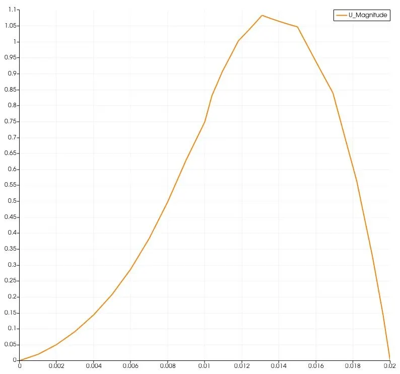
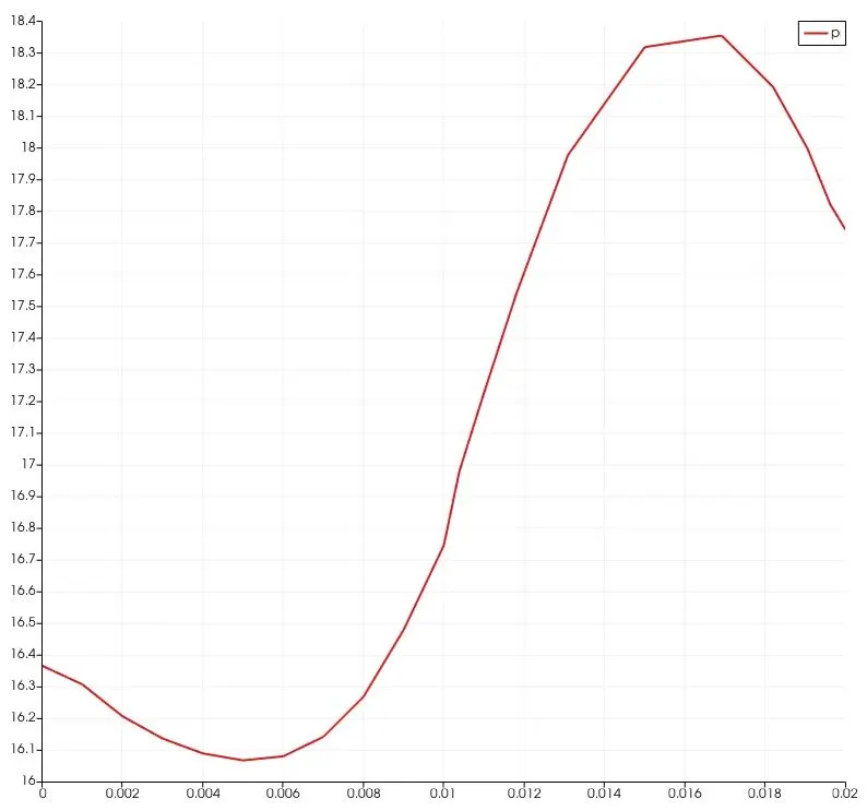
Case 2: GF =0.2
i) mesh
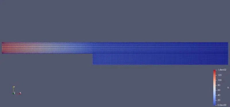
ii) velocity at x=0.85
iii) pressure at x=0.85
code: blockMeshDict
scale   0.1;

vertices
(
    (0 0 0)             //0
    (0.8 0 0)           //1
    (0.8 0.05 0)        //2
    (0 0.05 0)          //3
    (0.8 0.1 0)         //4
    (0 0.1 0)           //5
    (2 0.1 0)           //6
    (2 0.05 0)          //7
    (2 0 0)             //8
    (2 -0.1 0)          //9
    (0.8 -0.1 0)        //10
    (0 0 0.1)           //11
    (0.8 0 0.1)         //12
    (0.8 0.05 0.1)      //13
    (0 0.05 0.1)        //14
    (0.8 0.1 0.1)       //15
    (0 0.1 0.1)         //16
    (2 0.1 0.1)         //17
    (2 0.05 0.1)        //18
    (2 0 0.1)           //19
    (2 -0.1 0.1)        //20
    (0.8 -0.1 0.1)      //21

);

blocks
(
    hex (0 1 2 3 11 12 13 14) (80 5 1) simpleGrading (1 5 1)       // block 0
    hex (3 2 4 5 14 13 15 16) (80 5 1) simpleGrading (1 0.2 1)         // block 1
    hex (2 7 6 4 13 18 17 15) (120 5 1) simpleGrading (1 0.2 1)      // block 2
    hex (1 8 7 2 12 19 18 13) (120 5 1) simpleGrading (1 5 1)        // block 3
    hex (10 9 8 1 21 20 19 12) (120 10 1) simpleGrading (1 1 1)      // block 4

);

edges
(
);

boundary
(
    inletFace
    {
        type patch;
        faces
        (
            (5 3 14 16)
            (3 0 11 14)
        );
    }
    outletFace
    {
        type patch;
        faces
        (
            (6 17 18 7)
            (7 18 19 8)
            (8 19 20 9)
        );
    }
    fixedWalls
    {
        type wall;
        faces
        (
            (4 5 16 15)
            (0 1 12 11)
            (6 4 15 17)
	        (10 9 20 21)
	        (1 10 21 12)
        );
    }
    frontAndBack
    {
        type empty;
        faces
        (
            (15 16 14 13)
            (13 14 11 12)
	        (17 15 13 18)
	        (18 13 12 19)
	        (19 12 21 20)
            (5 4 2 3)
	        (3 2 1 0)
	        (4 6 7 2)
	        (2 7 8 1)
	        (1 8 9 10)
        );
    }
);

mergePatchPairs
(
);
code: U
dimensions      [0 1 -1 0 0 0 0];

internalField   uniform (0 0 0);

boundaryField
{
    inletFace
    {
        type            fixedValue;
        value           uniform (1 0 0);
    }

    outletFace
    {
        type zeroGradient;
    }

    fixedWalls
    {
        type            noSlip;
    }

    frontAndBack
    {
        type            empty;
    }
}
code p:
dimensions      [0 2 -2 0 0 0 0];

internalField   uniform 0;

boundaryField
{
    inletFace
    {
        type            zeroGradient;
    }

    outletFace
    {
        type            fixedValue;
        value           uniform 0;
    }

    fixedWalls
    {
        type            zeroGradient;
    }

    frontAndBack
    {
        type            empty;
    }
}
** Importance of growth factor:
Generally if number of cells in the domain are high, the time and computational power increase proportionally. To achieve high accuracy in simulation results, higher number of cells are preffered. For the simulation which involve capture of purtubations in turbulance or similar phenomena, finer cells are required. To overcome the problem of limited computational power, one way to get better accuracy in reusults if making the grid finer in the areas where changes ocuured in physical properties are very drastic and dynamic. So growth factor is used to make non-uniform mesh. Growth factor is ratio of size of final cell to size of first cell.