Week 8 - Simulation of a backward facing step in OpenFOAM
Aim: To simulate an incompressible-laminar-viscous flow through the backward facing step geometry.
Tasks:
To perform a transient simulation.
The solver can be chosen based on the described physics of the flow.
You need to explain the entire simulation procedure (how you set up the case).
You should also provide explanations to every change you make inside the reference case files obtained from OpenFOAM tutorials.
STEP 1 : Selection of tutorial
- Open the Terminal Window.
Here are the list of commands used in the prgram to navigate and copy the tutorial
1. ls (list) command lists all files and folders in your current working directory.
2. cd (change director”) Linux command also known as chdir used to change the current working directory.
Using this command is easy, just type cd followed by the the folder name.
You can use full paths to folders or simply the name of a folder within the directory you are currently working. Some common uses are:
- cd / – Takes you to the root directory.
- cd .. – Takes you up one directory level.
- cd – – Takes you to the previous directory.
3. cp (copy) Linux command allows you to copy a file.
You should specify both the file you want to be copied and the location you want it copied to
for example, cp xyz /home/myfiles would copy the file “xyz” to the directory “/home/myfiles”.
Option 'r' with the copy command can be used to copy a directory including all its content from a source directory to the destination directory
Navigation to tutorial
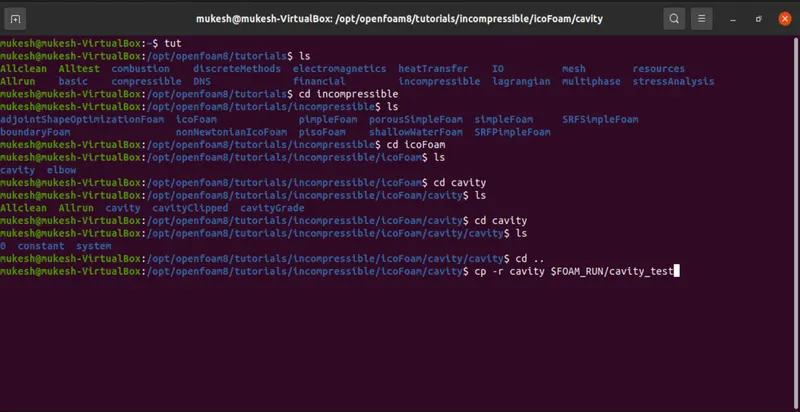
Here in tutorial we selcted incompressible tutorial as mentioned in the aim.
Then in incompressible directory we selected icoFoam because icoFoam solves the incompressible laminar Navier-Stokes equations using the PISO algorithm.
The code is inherently transient, requiring an initial condition (such as zero velocity) and boundary conditions.
Then next we select cavity as the doamain is a cavity
STEP 2 : Creating Mesh File
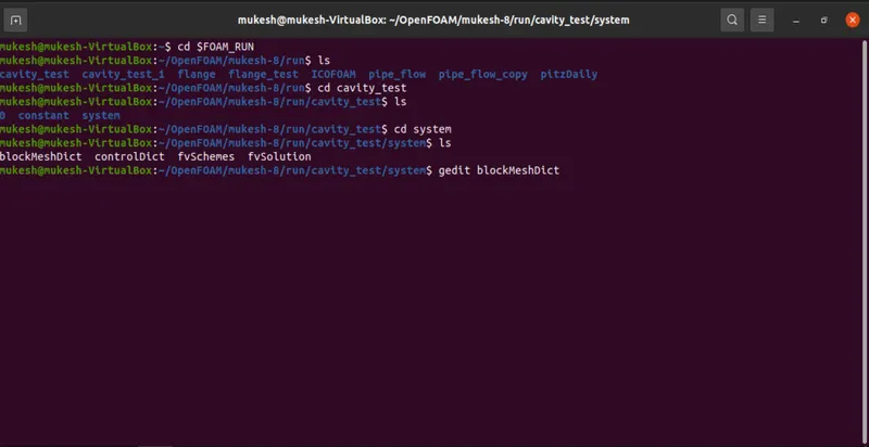
-Now navigating to run folder using FOAM_RUN/cavity_test/system
-Here we need to edit the blockMeshDict file using gedit command
4. gedit : Text Editor (gedit) is the default GUI text editor in the Ubuntu operating system
So below is the blockMeshDict file
/*--------------------------------*- C++ -*----------------------------------*\
  =========                 |
  \\      /  F ield         | OpenFOAM: The Open Source CFD Toolbox
   \\    /   O peration     | Website:  https://openfoam.org
    \\  /    A nd           | Version:  8
     \\/     M anipulation  |
\*---------------------------------------------------------------------------*/
FoamFile
{
    version     2.0;
    format      ascii;
    class       dictionary;
    object      blockMeshDict;
}
// * * * * * * * * * * * * * * * * * * * * * * * * * * * * * * * * * * * * * //

convertToMeters 0.1;

vertices
(
    (0 0 0)
    (1 0 0)
    (1 1 0)
    (0 1 0)
    (0 0 0.1)
    (1 0 0.1)
    (1 1 0.1)
    (0 1 0.1)
);

blocks
(
    hex (0 1 2 3 4 5 6 7) (20 20 1) simpleGrading (1 1 1)
);

edges
(
);

boundary
(
    movingWall
    {
        type wall;
        faces
        (
            (3 7 6 2)
        );
    }
    fixedWalls
    {
        type wall;
        faces
        (
            (0 4 7 3)
            (2 6 5 1)
            (1 5 4 0)
        );
    }
    frontAndBack
    {
        type empty;
        faces
        (
            (0 3 2 1)
            (4 5 6 7)
        );
    }
);

mergePatchPairs
(
);

// ************************************************************************* //
Here we have changed following things
(1) Scaling: convertToMeters 1 because we are going to enter values in meters
(2) vertices : we need to vizualize and calculate the vertex
(3) Blocks: there are 5 blocks and we need to name accordingly using vertex no. with mesh grid of 200*20*1 in X-Y-Z dirction with uniform grading i.e. (1 1 1)
(4) Boundary Conditions:
We need to mention the faces with different boundaries as here we have used four boundaries stated below
(i) inlet (ii) outlet (iii) fixedWalls (iv) frontAndBack
The given boundary conditions are,
1.Inlet: (Type patch)
The faces that contribute to inlet boundary are shown above. If we are looking at these faces from the outside, the definition of inlet boundary will be in counter-clockwise direction,
(0 11 14 3)
(3 14 16 5)
2.Outlet: (Type patch)
Similarly, we have 3 faces contributing to the outlet boundary condition. Since we are viewing the faces from outside, hence the definition of the outlet boundary will be in counter-clockwise direction,
(9 8 19 20)
(8 7 18 19)
(7 6 17 18)
Now for the other boundary look at the images below and repeat the steps to define the boundaries.
3.Front & Back: (Type empty)
4.No Slip walls: (Type wall)
/*--------------------------------*- C++ -*----------------------------------*\
  =========                 |
  \\      /  F ield         | OpenFOAM: The Open Source CFD Toolbox
   \\    /   O peration     | Website:  https://openfoam.org
    \\  /    A nd           | Version:  8
     \\/     M anipulation  |
\*---------------------------------------------------------------------------*/
FoamFile
{
    version     2.0;
    format      ascii;
    class       dictionary;
    object      blockMeshDict;
}
// * * * * * * * * * * * * * * * * * * * * * * * * * * * * * * * * * * * * * //

convertToMeters 1;

vertices
(
    (0 0 0)		//0
    (0.08 0 0)		//1
    (0.08 0.005 0)	//2
    (0 0.005 0)	//3
    (0.08 0.01 0)	//4
    (0 0.01 0)		//5
    (0.2 0.01 0)	//6
    (0.2 0.005 0)	//7
    (0.2 0 0)		//8
    (0.2 -0.01 0)	//9
    (0.08 -0.01 0)	//10
    (0 0 0.1)		//11
    (0.08 0 0.1)	//12
    (0.08 0.005 0.1)	//13
    (0 0.005 0.1)	//14
    (0.08 0.01 0.1)	//15
    (0 0.01 0.1)	//16
    (0.2 0.01 0.1)	//17
    (0.2 0.005 0.1)	//18
    (0.2 0 0.1)	//19
    (0.2 -0.01 0.1)	//20
    (0.08 -0.01 0.1)	//21
);

blocks
(
    hex (0 1 2 3 11 12 13 14)  (200 20 1) simpleGrading (1 1 1) // Block 1
    hex (3 2 4 5 14 13 15 16)  (200 20 1) simpleGrading (1 1 1) // Block 2
    hex (2 7 6 4 13 18 17 15)  (200 20 1) simpleGrading (1 1 1) // Block 3
    hex (1 8 7 2 12 19 18 13)  (200 20 1) simpleGrading (1 1 1) // Block 4
    hex (10 9 8 1 21 20 19 12) (200 20 1) simpleGrading (1 1 1) // Block 5
);

edges
(
);

boundary
(
    inlet
    {
        type patch;
        faces
        (
            (0 11 14 3)
            (3 14 16 5)
        );
    }
    outlet
    {
        type patch;
        faces
        (
            (9 8 19 20)
            (8 7 18 19)
            (7 6 17 18)
        );
    }
    fixedWalls
    {
        type wall;
        faces
        (
            (6 4 15 17)
            (4 5 16 15)
            (10 21 12 1)
            (12 11 0 1)
            (20 21 10 9)
        );
    }
    frontAndBack
    {
        type empty;
        faces
        (
            (0 3 2 1)
            (3 5 4 2)
            (2 4 6 7)
            (1 2 7 8)
            (10 1 8 9)
            (14 13 15 16)
            (11 12 13 14)
            (13 18 17 15)
            (12 19 18 13)
            (21 20 19 12)
        );
    }
);

mergePatchPairs
(
);

// ************************************************************************* //
After defining the boundaries correctly, to check if we have given defined them correctly, we need to execute the blockMesh command in the terminal.
Now open paraFoam, select all the patches and click apply. We will now be able to see the boundary conditions that have been applied to the geometry.
STEP 3: Creating Control File
Here we have to give intial conditions in controlDict file via gedit command
/*--------------------------------*- C++ -*----------------------------------*\
  =========                 |
  \\      /  F ield         | OpenFOAM: The Open Source CFD Toolbox
   \\    /   O peration     | Website:  https://openfoam.org
    \\  /    A nd           | Version:  8
     \\/     M anipulation  |
\*---------------------------------------------------------------------------*/
FoamFile
{
    version     2.0;
    format      ascii;
    class       dictionary;
    location    "system";
    object      controlDict;
}
// * * * * * * * * * * * * * * * * * * * * * * * * * * * * * * * * * * * * * //

application     icoFoam;

startFrom       startTime;

startTime       0;

stopAt          endTime;

endTime         0.2;

deltaT          0.00001;

writeControl    timeStep;

writeInterval   20;

purgeWrite      0;

writeFormat     ascii;

writePrecision  6;

writeCompression off;

timeFormat      general;

timePrecision   6;

runTimeModifiable true;


// ************************************************************************* //
STEP 4: Setting UP Intial properties of pressure and velocity
Pressure:
/*--------------------------------*- C++ -*----------------------------------*\
  =========                 |
  \\      /  F ield         | OpenFOAM: The Open Source CFD Toolbox
   \\    /   O peration     | Website:  https://openfoam.org
    \\  /    A nd           | Version:  8
     \\/     M anipulation  |
\*---------------------------------------------------------------------------*/
FoamFile
{
    version     2.0;
    format      ascii;
    class       volScalarField;
    object      p;
}
// * * * * * * * * * * * * * * * * * * * * * * * * * * * * * * * * * * * * * //

dimensions      [0 2 -2 0 0 0 0];

internalField   uniform 0;

boundaryField
{
    inlet
    {
        type            zeroGradient;
    }

    outlet
    {
        type            fixedValue;
        value		 uniform 0;
    }

    fixedWalls
    {
    	type		zeroGradient;
    }
    frontAndBack
    {
        type            empty;
    }
}

// ************************************************************************* //
Velocity:
/*--------------------------------*- C++ -*----------------------------------*\
  =========                 |
  \\      /  F ield         | OpenFOAM: The Open Source CFD Toolbox
   \\    /   O peration     | Website:  https://openfoam.org
    \\  /    A nd           | Version:  8
     \\/     M anipulation  |
\*---------------------------------------------------------------------------*/
FoamFile
{
    version     2.0;
    format      ascii;
    class       volVectorField;
    object      U;
}
// * * * * * * * * * * * * * * * * * * * * * * * * * * * * * * * * * * * * * //

dimensions      [0 1 -1 0 0 0 0];

internalField   uniform (0 0 0);

boundaryField
{
    inlet
    {
        type            fixedValue;
        value           uniform (1 0 0);
    }
    outlet
    {
    	type		zeroGradient;
    }
    fixedWalls
    {
        type            noSlip;
        value		uniform (0 0 0);
    }
    }
    frontAndBack
    {
        type            empty;
    }
}

// ************************************************************************* //
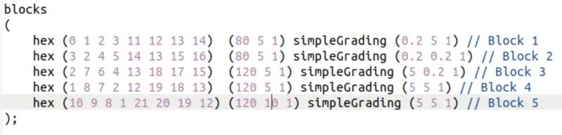
Case 2 - Simulate the flow with grading factor of 0.2.
The cells should be finer near the walls (includig the step wall).
So, here we are changing the grading factor to 0.2 and 1/0.2=5 in blockMeshDict file
output
- To generate the output first we need to use blockMesh command to generate the mesh
- After that we need to give the command to start the simulation ,so the name of the command will be same as the name of the directory so we have taken the example from icoFoam directory so we will use the same name as command to run the simulation
- After that to view the simulation or mesh we use the command paraFoam
- Then we need to click on apply in properties menu to vizualize the mesh
- To view velocity profile we need to select velocity U and start the play buttton to vizualize the velocity and wait till end it gets stabalize
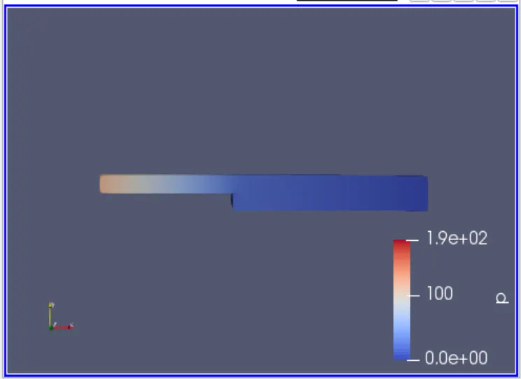
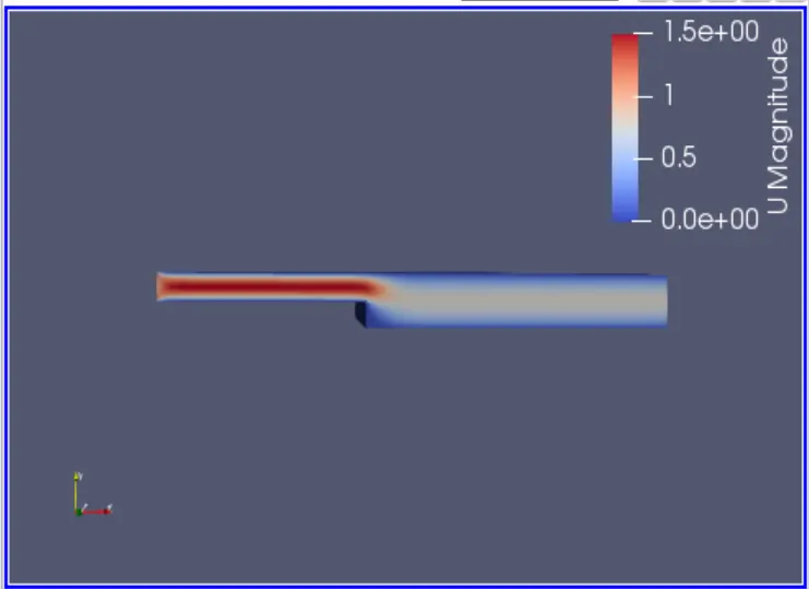
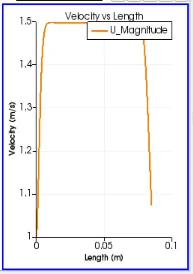
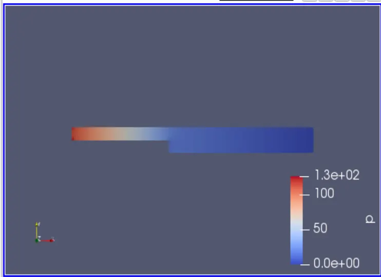
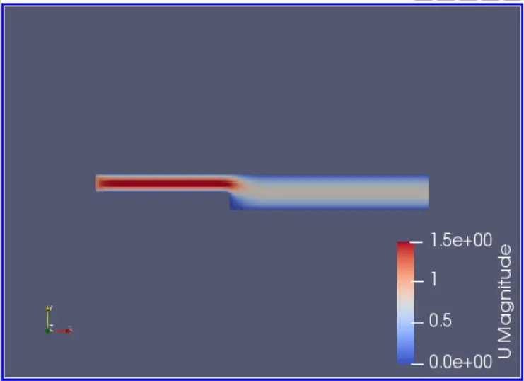
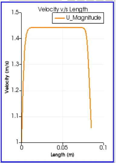
- Now we have measured the velocity profile at 0.085 m from the inlet of the geometry for both cases.
Case-1
Case - 2
Results and Discussion
By comparing the above two results the maximum velocity is 1.5 m/s while in case -2 is refined to 1.45 m/s
So, grading factor is essential very essential to fine mesh where geometry is changing and to coarse mesh where there is little or no change in geometry it helps in saving the computaional power by deciding what is more important