A program to solve the forward kinematics problem of a 2R Robotic Arm Manipulator using MATLAB
INTRODUTION:
If we can able to figure out how robot is going to move then we can figur out its workspace
Workspace : The possible loctions where the robot can reach
This is important when robots are designed for complex applications such as welding
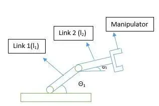
Description of the diagram:
As you can see in the above diagram there are two linkages i.e. link1 and link 2.
The one end of link 1 is connected with the fixed ground via rotational joint while the other hand is connected with the link 2 via another rotational joint
The one end of link 2 is conneted with the link 1 and the other end is connected with the Manipulator
Here,
L1= Length of the link 1
L2= Length of the link 2
Θ1= Angle made by link 1 with the horizontal surface
Θ2= Angle made by link 2 with the horizontal surface
Problem:
If θ1 and θ2 are given what is the position of the manipulator
Solution:
Calculate the position of link 1
Let the starting point of link 1 be A (0,0) and ending point of the link be B(l1*cosθ1, 12*sinθ1)
Calculate the position of link 2
So, the starting point of the link 2 will be the ending point of link 1 i.e. B(x1,y1)
And the ending point of the link 2 will be the position oc the manipulator i.e.
C(x2,y2)=c(x1+l2*cosθ2, y1+l2*sinθ2)
MATLAB CODE WITH LINE TO LINE EXPLANATION WITH THE HELP OF COMMENTS
clc % It clears the command window
clear % It clears the variables

fr=1;

% Let define the length of the robotic arm
l1=5;
l2=2.5;

for i= [0 30 45 60 90]
    % Lets define the angles at which the robotic arm will move
    theta1=i;

    for j=[0 30 45 60 90]
        theta2=j;
        % Let define the co-orinate points of the robotic arm
        a=[0 0]; % denotes the starting fixed point of robotic arm
        b=[0+l1*cosd(theta1) 0+l1*sind(theta1)]; % denotes the end point of first link arm & starting point of second link arm
        c=[b(1)+l2*cosd(theta2) b(2)+l2*sind(theta2)]; % denotes the end point of second link arm

        plot([a(1) b(1)],[a(2) b(2)],[b(1),c(1)],[b(2),c(2)]) % this will plot the diagram
        axis([-0.1 10.5 0   10.5]) %This will describe the range of x & y co-ordinate
        xlabel('X-axis') % Denotes the subtitle for x-axis
        ylabel('Y-axis') % Denotes the subtitle for y-axis
        pause(0.3)

        M(fr)=getframe(gcf); %M denotes movie with fr frames
                             %getframe will form gcf=current figure handle
        fr=fr+1; % fr=No. of frames, intiated as fr=1
    end
end

movie(M) % binding frames into movie
videofile=VideoWriter('robotarm.avi','Uncompressed AVI'); %Creating video file
open(videofile) % opening the video file
writeVideo(videofile,M) % writing the video file
close(videofile) % closing the video file
- Errors encountered while running the code
Error 1: To construct matrices, use brackets instead of parentheses.
- Before: a=(0 0)
- After: a=[0 0]
Error 2: Unable to resolve the name robotarm.avi.
- Before: videofile=VideoWriter(robotarm.avi,'Uncompressed AVI');
- After: videofile=VideoWriter('robotarm.avi','Uncompressed AVI');
Error 3: Cannot find an exact (case-sensitive) match for 'videowriter'
- Before: videofile=videowriter('robotarm.avi','Uncompressed AVI');
- After: videofile=VideoWriter('robotarm.avi','Uncompressed AVI');
OUTPUT VIDEO:
CONCLUSION:
- The above project gives us output as an animated file which mimic the robotic arm
- So, various possibilities were like to take the co-ordinates of the point separately or as an array