Week 8 - Simulation of a backward facing step in OpenFOAM
Aim:- to simulate an incompressible-laminar-viscous flow through the backward-facing step geometry.
Af
Case 1 - Simulate the flow without using any grading factor (i.e., GF = 1)
Case 2 - Simulate the flow with a grading factor of 0.2. The cells should be finer near the walls (including the step wall).
Mesh specification
- Number of cells along the x-direction (longer dimension) = 200
- Number of cells along the longer y-direction = 20;
Boundary condition specification
The domain specifications are provided in the following figure.
Desired output
- Measure the velocity profile at 0.085 m from the inlet of the geometry for both case studies and compare. You can use the plot overline tool for this.
- Explain why the Grading/Growth factor is essential for meshing.
Geometry Creation:-
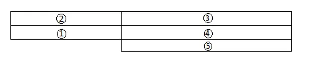
- Firstly we divide our geometry into 5 block
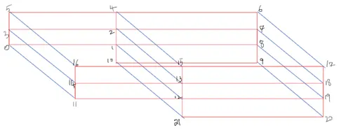
- Now we will define vertices
- Definig blocks
we use hex command and mensioning the vertices of the block
hex (0 1 2 3 11 12 13 14) (1 1 1) simpleGrading (1 1 1)
simple grading: help to refine the grid from one direction
we have to feed the value of the grading factor which will refine the shell
grading factor = size of last cell/ size of the first cell
Meshing:
Now to mesh the geometry fill in the number of cells in x, y, and z-direction inside the second parenthesis of the Hex command,
i.e., hex(0 1 2 3 11 12 13 14) (10 10 1) simple grading(1 1 1).
since this is a 2D problem, increasing the number of cells in the z-direction, doesn’t make sense. To view the mesh in para form, select the surface with edges option and view the mesh.
Boundary Conditions:
1.Inlet: (Type patch)
The faces that contribute to inlet boundary are shown above. If we are looking at these faces from the outside, the definition of inlet boundary will be in the counter-clockwise direction,
(0 11 14 3)
(3 14 16 5)
2.Outlet: (Type patch)
Similarly, we have 3 faces contributing to the outlet boundary condition. Since we are viewing the faces from outside, hence the definition of the outlet boundary will be in counter-clockwise direction,
(9 8 19 20)
(8 7 18 19)
(7 6 17 18)
Now for the other boundary look at the images below and repeat the steps to define the boundaries.
3.Front & Back: (Type empty)
4.No Slip walls: (Type wall)
After defining the boundaries correctly, to check if you have given defined them correctly, execute the blockMesh command in the terminal.Now open paraFoam, select all the patches and click apply. You will now be able to see the boundary conditions that have been applied to the geometry.
As part of the Challenge, figure out the right initial conditions.
PROCEDURE:-
- Firstly, we have to search for the solver/tutorial in OpenFOAM which will be used to solve our problem. The type of solver depends on the nature of the problem we Re trying to solve.
- Here, for our incompressible laminar viscous flow, the solver used is "icoFoam". in which we will use a "cavity'' solver.
- After locating we have to copy the 'cavity' solver from icoFoam, in the copied file we can make changes in it. Because we can't make changes directly to the main folder.
- Now, we will create our geometry, which is done in the blockMeshDict file present in the solver. But, before that, we have to divide our geometry into blocks, faces, and vertices. all this input will be used to create our geometry in OpenFOAM.
- The geometry specification is no. of blocks are 5 and vertices are 21. in OpenFOAM faces are called patches.
- Now we specified all parameters that are used to create geometry in block mesh.
- Now we will provide boundary conditions.
- finally, we have to provide an initial condition of pressure and velocity which is done in zero folder.
- now we can run our simulation by just typing icoFoam and view the results we type paraview.
/*--------------------------------*- C++ -*----------------------------------*
  =========                 |
  \      /  F ield         | OpenFOAM: The Open Source CFD Toolbox
   \    /   O peration     | Website:  https://openfoam.org
    \  /    A nd           | Version:  8
     \/     M anipulation  |
*---------------------------------------------------------------------------*/
FoamFile
{
    version     2.0;
    format      ascii;
    class       dictionary;
    object      blockMeshDict;
}
// * * * * * * * * * * * * * * * * * * * * * * * * * * * * * * * * * * * * * //

convertToMeters 0.01;

vertices
(
    (0 0 0)
    (8 0 0)
    (8 0.5 0)
    (0 0.5 0)
    (8 1 0)
    (0 1 0)
    (20 1 0)
    (20 0.5 0)
    (20 0 0)
    (20 -1 0)
    (8 -1 0)

    (0 0 0.6)
    (8 0 0.6)
    (8 0.5 0.6)
    (0 0.5 0.6)
    (8 1 0.6)
    (0 1 0.6)
    (20 1 0.6)
    (20 0.5 0.6)
    (20 0 0.6)
    (20 -1 0.6)
    (8 -1 0.6)


);

blocks
(
    hex (0 1 2 3 11 12 13 14) (80 10 1) simpleGrading (1 1 1)

    hex (3 2 4 5 14 13 15 16) (80 10 1) simpleGrading (1 1 1)

    hex (2 7 6 4 13 18 17 15) (120 10 1) simpleGrading (1 1 1)

    hex (1 8 7 2 12 19 18 13) (120 10 1) simpleGrading (1 1 1)

    hex (10 9 8 1 21 20 19 12) (120 20 1) simpleGrading (1 1 1)

);

edges
(
);

boundary
(
    inlet
    {
        type patch;
        faces
        (
            (0 11 14 3)
            (3 14 16 5)

        );
    }
    outlet
    {
        type patch;
        faces
        (
            (9 8 19 20)
            (8 7 18 19)
            (7 6 17 18)
        );
    }
    frontAndBack
    {
        type empty;
        faces
        (
            (0 3 2 1)
            (11 12 13 14)
            (3 5 4 2)
            (13 15 16 14)
            (2 4 6 7)
            (13 18 17 15)
            (1 2 7 8)
            (12 19 18 13)
            (10 1 8 9)
            (21 20 19 12)


        );
    }

        noslipwall
    {
        type wall;
        faces
        (
            (4 5 16 15)
            (4 15 17 6)
            (0 1 12 11)
            (9 20 21 10)
            (1 10 21 12)

        );
    }

);

mergePatchPairs
(

);

// ************************************************************************* //
with grading factor 0.2
/*--------------------------------*- C++ -*----------------------------------*
  =========                 |
  \      /  F ield         | OpenFOAM: The Open Source CFD Toolbox
   \    /   O peration     | Website:  https://openfoam.org
    \  /    A nd           | Version:  8
     \/     M anipulation  |
*---------------------------------------------------------------------------*/
FoamFile
{
    version     2.0;
    format      ascii;
    class       dictionary;
    object      blockMeshDict;
}
// * * * * * * * * * * * * * * * * * * * * * * * * * * * * * * * * * * * * * //

convertToMeters 0.01;

vertices
(
    (0 0 0)
    (8 0 0)
    (8 0.5 0)
    (0 0.5 0)
    (8 1 0)
    (0 1 0)
    (20 1 0)
    (20 0.5 0)
    (20 0 0)
    (20 -1 0)
    (8 -1 0)

    (0 0 0.6)
    (8 0 0.6)
    (8 0.5 0.6)
    (0 0.5 0.6)
    (8 1 0.6)
    (0 1 0.6)
    (20 1 0.6)
    (20 0.5 0.6)
    (20 0 0.6)
    (20 -1 0.6)
    (8 -1 0.6)


);

blocks
(
    hex (0 1 2 3 11 12 13 14) (80 10 1) simpleGrading (0.2 5 1)

    hex (3 2 4 5 14 13 15 16) (80 10 1) simpleGrading (0.2 0.2 1)

    hex (2 7 6 4 13 18 17 15) (120 10 1) simpleGrading (5 0.2 1)

    hex (1 8 7 2 12 19 18 13) (120 10 1) simpleGrading (5 5 1)

    hex (10 9 8 1 21 20 19 12) (120 20 1) simpleGrading (5 5 1)

);

edges
(
);

boundary
(
    inlet
    {
        type patch;
        faces
        (
            (0 11 14 3)
            (3 14 16 5)

        );
    }
    outlet
    {
        type patch;
        faces
        (
            (9 8 19 20)
            (8 7 18 19)
            (7 6 17 18)
        );
    }
    frontAndBack
    {
        type empty;
        faces
        (
            (0 3 2 1)
            (11 12 13 14)
            (3 5 4 2)
            (13 15 16 14)
            (2 4 6 7)
            (13 18 17 15)
            (1 2 7 8)
            (12 19 18 13)
            (10 1 8 9)
            (21 20 19 12)


        );
    }

        noslipwall
    {
        type wall;
        faces
        (
            (4 5 16 15)
            (4 15 17 6)
            (0 1 12 11)
            (9 20 21 10)
            (1 10 21 12)

        );
    }

);

mergePatchPairs
(

);

// ************************************************************************* //
now we will define initial pressure and velocity in zero folder
PRESSURE
/*--------------------------------*- C++ -*----------------------------------*
  =========                 |
  \      /  F ield         | OpenFOAM: The Open Source CFD Toolbox
   \    /   O peration     | Website:  https://openfoam.org
    \  /    A nd           | Version:  8
     \/     M anipulation  |
*---------------------------------------------------------------------------*/
FoamFile
{
    version     2.0;
    format      ascii;
    class       volScalarField;
    object      p;
}
// * * * * * * * * * * * * * * * * * * * * * * * * * * * * * * * * * * * * * //

dimensions      [0 2 -2 0 0 0 0];

internalField   uniform 0;

boundaryField
{
    inlet
    {
        type            zeroGradient;
    }

    outlet
    {
        type            fixedValue;
        value           uniform 0;
    }

    frontAndBack
    {
        type            empty;
    }
    noslipwall
    {
        type            zeroGradient;
    }
}

// ************************************************************************* //
 VELOCITY FILE

/*--------------------------------*- C++ -*----------------------------------*
  =========                 |
  \      /  F ield         | OpenFOAM: The Open Source CFD Toolbox
   \    /   O peration     | Website:  https://openfoam.org
    \  /    A nd           | Version:  8
     \/     M anipulation  |
*---------------------------------------------------------------------------*/
FoamFile
{
    version     2.0;
    format      ascii;
    class       volVectorField;
    object      U;
}
// * * * * * * * * * * * * * * * * * * * * * * * * * * * * * * * * * * * * * //

dimensions      [0 1 -1 0 0 0 0];

internalField   uniform (0 0 0);

boundaryField
{
    inlet
    {
        type            fixedValue;
        value           uniform (0.066 0 0);
    }

    outlet
    {
        type            zeroGradient;
    }

    frontAndBack
    {
        type            empty;
    }
    noslipwall
    {
        type            noSlip;
    }
}

// ************************************************************************* //
OUTPUT
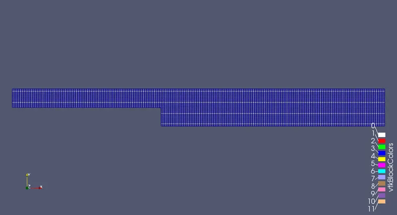
Without assigning any grading factor the block mesh is as shown below.
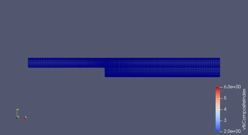
For the given grading factor 0.2 the results are as follows.
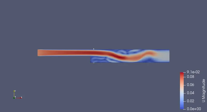
The velocity flow diagram without applying grading factor.
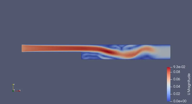
The velocity flow diagram for the grading factor 0.2
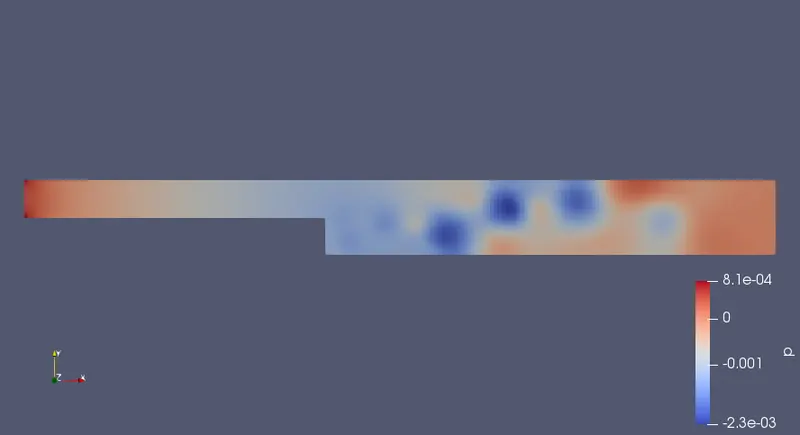
The pressure flow diagram without applying grading factor.
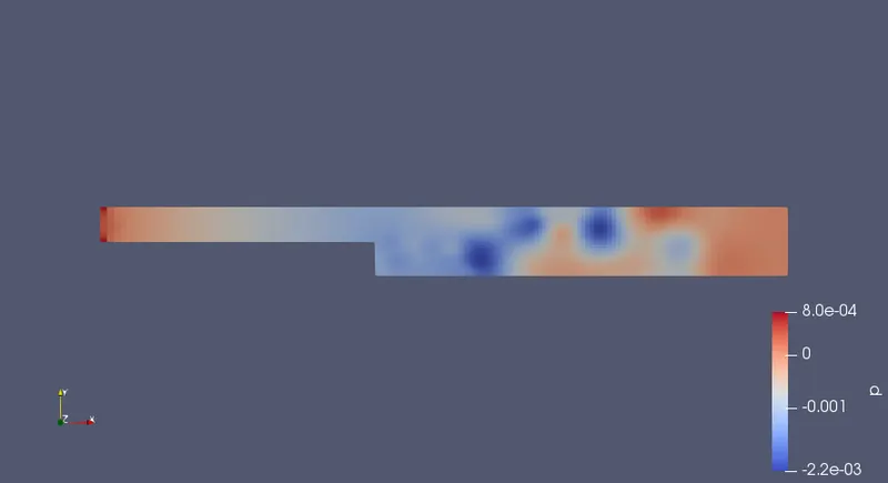
The pressure flow diagram for the given grading factor 0.2
The plot for the velocity at 0.085 without applying grading fcator.
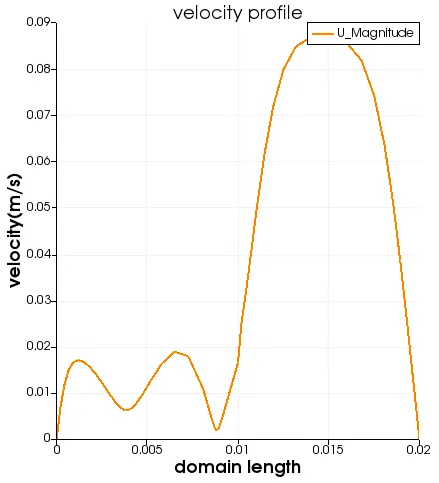
The plot for the velocity at 0.085 for the given grading fcator 0.2 is as follows.
CONCLUSION.
BY changing the grading factor we are getting a smoother cure as compared to grading factor =1 and results are more accurate therefore result get affected when the grading factor changes but change is not significant in our case.