Week 8 - Simulation of a backward facing step in OpenFOAM
Objective :
- To simulate an incompressible-laminar-viscous flow through the backward facing step geometry and the flow should be transient.
- To measure the velocity profile at 0.085 m from the inlet of the geometry for both case studies which is for grading factor = 1 and grading factor = 0.2, the cells should be finer near the walls (includig the step wall).
- To explain why Grading/Growth factor is essential for meshing.
Mesh specification :
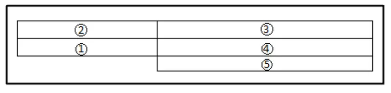
- Number of cells along the x direction (longer dimension) = 200mm
- Number of cells along the longer y direction = 20;
Incompressible flow :
A flow with no change in density is known as incompressible flow.
Laminar flow :
Fluid flows can be divided into two different types: laminar flows and turbulent flows. Laminar flow occurs when the fluid flows in infinitesimal parallel layers with no disruption between them. In laminar flows, fluid layers slide in parallel, with no eddies, swirls or currents normal to the flow itself. This type of flow is also referred to as streamline flow because it is characterized by non-crossing streamlines (figure 1).
The laminar regime is ruled by momentum diffusion, while the momentum convection is less important. In more physical terms, it means that viscous forces are higher than inertial forces.
Figure 1: (a) Laminar flow in a closed pipe, (b) Turbulent flow in a closed pipe
When the Reynolds no is less than 2000 the flow is said to be laminar .
Reynold's number :
- It is a dimensionless term which determines the flow of fluid is either laminar or turbulent.
- when the viscous force predominates over the inertia force the flow is said to be laminar.
Inertia force :
- Inertia force states that a particle will follow the same path with same velocity and move forever in its path if not any external force is applied to particle.
- So, simply inertia force represents the degree of freedom of a particle.
- If so then if viscosity increases it restricts the fluid to flow in a straight line having degree of freedom 1.
- So if viscous force is more than inertia force the internal friction between the fluid particles (viscosity force) will not allow the fluid particles to remain in their usual physical characteristics. I mean their velocities and direction of moving rather it willl just force it to obey a straight path with lesser velocities.
- At low velocities the fluid particles flows in stream line and they do not mix with each other.
- The velocity which determines the flow to be laminar or critical is termed as critical velocity.
Critical velocity :
The velocity below which a flow is laminar and above which a flow is turbulent is the critical velocity.
Mesh grading :
Mesh grading is a factor which is the ratio of size of last cell to the size of the first cell.
Procedure :
- Firstly open the terminal in linux operating system by simply right clicking and selecting open terminal option or else we can use a short cut key Ctrl+Alt+t.
- Then in that type 'tut' which directs to the tutorial folder.
- Then type 'ls' which shows the list of options available in the tutorial folder, In that select 'incompressible' flow which is our objective.
- Then again type 'ls' then select 'icoFoam' which is actually suitable for laminar nonviscous flows.
- Then again type 'ls' then select the 'cavity' folder in cavity folder again we are going to see another 'cavity' folder there we define fluid domain and generate block mesh. But we are not going to make changes in the tutorial section first of all open foam doesn't allow to makes changes directly in the tutorial folder because it will corrupt the openfoam we need to reinstall it again in order to rectify that issue.
- so we are going to copy this cavity folder using 'cp -r cavity' command and paste it in openfoam run folder by typing 'cp -r cavity $FOAM_RUN/ cavity_test'. And then open run folder by typing 'cd $FOAM_RUN'. Where we can see cavity_test file.
- Now we can make any changes to the cavity_test file, which will never affect the openfoam official files. open cavity-test folder. Here we can provide specification for our block mesh in the sytem folder.
- Then provide starting time and ending time and the value of deltat in the controldict folder in order to calculate the cfl number. Note we need to choose the value of deltat which satisfies the CFL stability criteria which is it should be less than 1 in order to provide a stable solution. If it doesn't satisfy the solution will get blowedup at any stage. Instead of converging the solution got diverged.
- Then provide initial and boundary condition for velocity and pressure in '0' folder which is present inside the cavity test folder.
Program :
BlockMeshDict file :
For simple grading(G.F =1):
/*--------------------------------*- C++ -*----------------------------------*
  =========                 |
        /  F ield         | OpenFOAM: The Open Source CFD Toolbox
       /   O peration     | Website:  https://openfoam.org
      /    A nd           | Version:  9
     /     M anipulation  |
*---------------------------------------------------------------------------*/
FoamFile
{
    format      ascii;
    class       dictionary;
    object      blockMeshDict;
}
// * * * * * * * * * * * * * * * * * * * * * * * * * * * * * * * * * * * * * //

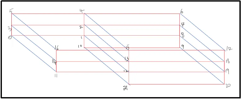
convertToMeters 0.01;

vertices
(
    (0 0 0)       //0
    (8 0 0)       //1
    (8 0.5 0)     //2
    (0 0.5 0)     //3
    (8 1 0)       //4
    (0 1 0)       //5
    (20 1 0)      //6
    (20 0.5 0)    //7
    (20 0 0)      //8
    (20 -1 0)     //9
    (8 -1 0)      //10
    (0 0 0.1)     //11
    (8 0 0.1)     //12
    (8 0.5 0.1)   //13
    (0 0.5 0.1)   //14
    (8 1 0.1)     //15
    (0 1 0.1)     //16
    (20 1 0.1)    //17
    (20 0.5 0.1)  //18
    (20 0 0.1)    //19
    (20 -1 0.1)   //20
    (8 -1 0.1)    //21
);

blocks
(
    hex (0 1 2 3 11 12 13 14) (80 5 1) simpleGrading (1 1 1)
    hex (3 2 4 5 14 13 15 16) (80 5 1) simpleGrading (1 1 1)
    hex (2 7 6 4 13 18 17 15) (120 5 1) simpleGrading (1 1 1)
    hex (1 8 7 2 12 19 18 13) (120 5 1) simpleGrading (1 1 1)
    hex (10 9 8 1 21 20 19 12) (120 10 1) simpleGrading (1 1 1)
);

edges
(
);

boundary
(
    inlet
    {
        type wall;
        faces
        (
            (0 11 14 3)
            (3 14 16 5)
        );
    }

    outlet
    {
        type patch;
        faces
        (
            (9 8 19 20)
            (8 7 18 19)
            (7 6 17 18)
        );
    }
    fixedWalls
    {
        type wall;
        faces
        (
            (5 16 15 4)
            (0 1 12 11)
            (4 15 17 6)
            (10 9 20 21)
            (10 21 12 1)
        );
    }
    frontAndBack
    {
        type empty;
        faces
        (
            (11 12 13 14)
            (14 13 15 16)
            (13 18 17 15)
            (12 19 18 13)
            (21 20 19 12)
            (0 3 2 1)
            (3 5 4 2)
            (2 4 6 7)
            (1 2 7 8)
            (10 1 8 9)
        );
    }
);

mergePatchPairs
(
);

// ************************************************************************* //
For Grading factor(0.2) :
/*--------------------------------*- C++ -*----------------------------------*
  =========                 |
        /  F ield         | OpenFOAM: The Open Source CFD Toolbox
       /   O peration     | Website:  https://openfoam.org
      /    A nd           | Version:  9
     /     M anipulation  |
*---------------------------------------------------------------------------*/
FoamFile
{
    format      ascii;
    class       dictionary;
    object      blockMeshDict;
}
// * * * * * * * * * * * * * * * * * * * * * * * * * * * * * * * * * * * * * //

convertToMeters 0.01;

vertices
(
    (0 0 0)       //0
    (8 0 0)       //1
    (8 0.5 0)     //2
    (0 0.5 0)     //3
    (8 1 0)       //4
    (0 1 0)       //5
    (20 1 0)      //6
    (20 0.5 0)    //7
    (20 0 0)      //8
    (20 -1 0)     //9
    (8 -1 0)      //10
    (0 0 0.1)     //11
    (8 0 0.1)     //12
    (8 0.5 0.1)   //13
    (0 0.5 0.1)   //14
    (8 1 0.1)     //15
    (0 1 0.1)     //16
    (20 1 0.1)    //17
    (20 0.5 0.1)  //18
    (20 0 0.1)    //19
    (20 -1 0.1)   //20
    (8 -1 0.1)    //21
);

blocks
(
    hex (0 1 2 3 11 12 13 14) (80 5 1) simpleGrading (0.2 5 1)
    hex (3 2 4 5 14 13 15 16) (80 5 1) simpleGrading (0.2 0.2 1)
    hex (2 7 6 4 13 18 17 15) (120 5 1) simpleGrading (5 0.2 1)
    hex (1 8 7 2 12 19 18 13) (120 5 1) simpleGrading (5 5 1)
    hex (10 9 8 1 21 20 19 12) (120 10 1) simpleGrading (5 5 1)
);

edges
(
);

boundary
(
    inlet
    {
        type wall;
        faces
        (
            (0 11 14 3)
            (3 14 16 5)
        );
    }

    outlet
    {
        type patch;
        faces
        (
            (9 8 19 20)
            (8 7 18 19)
            (7 6 17 18)
        );
    }
    fixedWalls
    {
        type wall;
        faces
        (
            (5 16 15 4)
            (0 1 12 11)
            (4 15 17 6)
            (10 9 20 21)
            (10 21 12 1)
        );
    }
    frontAndBack
    {
        type empty;
        faces
        (
            (11 12 13 14)
            (14 13 15 16)
            (13 18 17 15)
            (12 19 18 13)
            (21 20 19 12)
            (0 3 2 1)
            (3 5 4 2)
            (2 4 6 7)
            (1 2 7 8)
            (10 1 8 9)
        );
    }
);

mergePatchPairs
(
);

// ************************************************************************* //
Controldict file :
/*--------------------------------*- C++ -*----------------------------------*
  =========                 |
        /  F ield         | OpenFOAM: The Open Source CFD Toolbox
       /   O peration     | Website:  https://openfoam.org
      /    A nd           | Version:  9
     /     M anipulation  |
*---------------------------------------------------------------------------*/
FoamFile
{
    format      ascii;
    class       dictionary;
    location    "system";
    object      controlDict;
}
// * * * * * * * * * * * * * * * * * * * * * * * * * * * * * * * * * * * * * //

application     icoFoam;

startFrom       startTime;

startTime       0;

stopAt          endTime;

endTime         0.2;

deltaT          0.0001;

writeControl    timeStep;

writeInterval   20;

purgeWrite      0;

writeFormat     ascii;

writePrecision  6;

writeCompression off;

timeFormat      general;

timePrecision   6;

runTimeModifiable true;


// ************************************************************************* //
Transportproperties file :
/*--------------------------------*- C++ -*----------------------------------*
  =========                 |
        /  F ield         | OpenFOAM: The Open Source CFD Toolbox
       /   O peration     | Website:  https://openfoam.org
      /    A nd           | Version:  9
     /     M anipulation  |
*---------------------------------------------------------------------------*/
FoamFile
{
    format      ascii;
    class       dictionary;
    location    "constant";
    object      transportProperties;
}
// * * * * * * * * * * * * * * * * * * * * * * * * * * * * * * * * * * * * * //

nu              [0 2 -1 0 0 0 0] 8.93e-7;


// ************************************************************************* //
Initial and Boundary conditons :
Pressure :
/*--------------------------------*- C++ -*----------------------------------*
  =========                 |
        /  F ield         | OpenFOAM: The Open Source CFD Toolbox
       /   O peration     | Website:  https://openfoam.org
      /    A nd           | Version:  9
     /     M anipulation  |
*---------------------------------------------------------------------------*/
FoamFile
{
    format      ascii;
    class       volScalarField;
    object      p;
}
// * * * * * * * * * * * * * * * * * * * * * * * * * * * * * * * * * * * * * //

dimensions      [0 2 -2 0 0 0 0];

internalField   uniform 0;

boundaryField
{
    inlet
    {
        type            zeroGradient;
    }

    outlet
    {
        type            fixedValue;
        value           uniform 0;
    }


    fixedWalls
    {
        type            zeroGradient;
    }

    frontAndBack
    {
        type            empty;
    }
}

// ************************************************************************* //
Velocity :
/*--------------------------------*- C++ -*----------------------------------*
  =========                 |
        /  F ield         | OpenFOAM: The Open Source CFD Toolbox
       /   O peration     | Website:  https://openfoam.org
      /    A nd           | Version:  9
     /     M anipulation  |
*---------------------------------------------------------------------------*/
FoamFile
{
    format      ascii;
    class       volVectorField;
    object      U;
}
// * * * * * * * * * * * * * * * * * * * * * * * * * * * * * * * * * * * * * //

dimensions      [0 1 -1 0 0 0 0];

internalField   uniform (0 0 0);

boundaryField
{
    inlet
    {
        type            fixedValue;
        value           uniform (1 0 0);
    }

    outlet
    {
        type            zeroGradient;

    }

    fixedWalls
    {
        type            noSlip;
    }

    frontAndBack
    {
        type            empty;
    }
}

// ************************************************************************* //
Result :
Mesh structure :
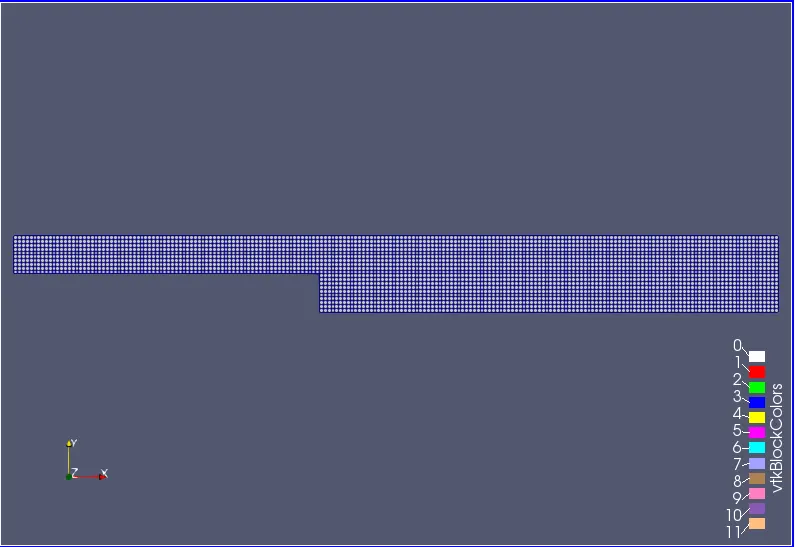
Fig(a) simple grading(G.F = 1)
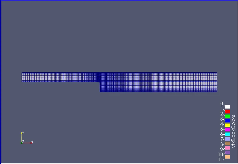
Fig(b) Grading factor =2
The above fig(a) and fig(b) shows that the mesh structure of backward facing step. In fig(a) there is constant mesh. In fig(b) the mesh structure is more finer near the walls and the step. The detailed structure of this two as shown below.
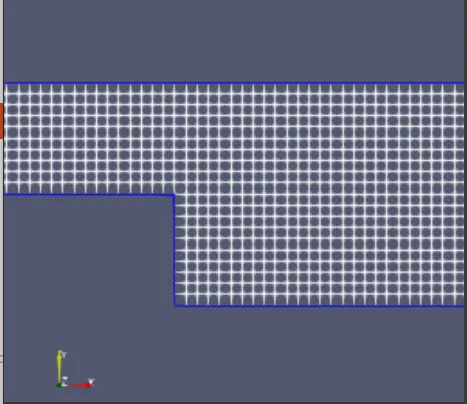
Fig(c) simple grading(G.F = 1)
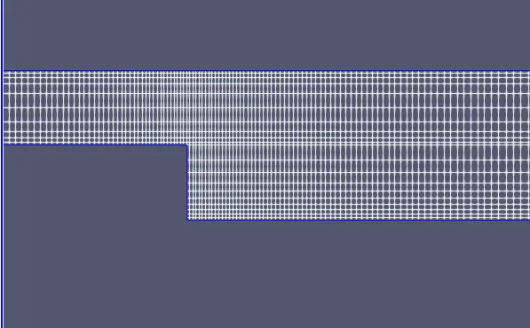
Fig(d) Grading factor =0.2
Change in velocity :
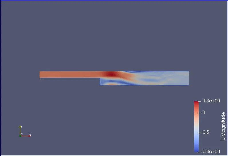
Fig(e) simple grading(G.F = 1)
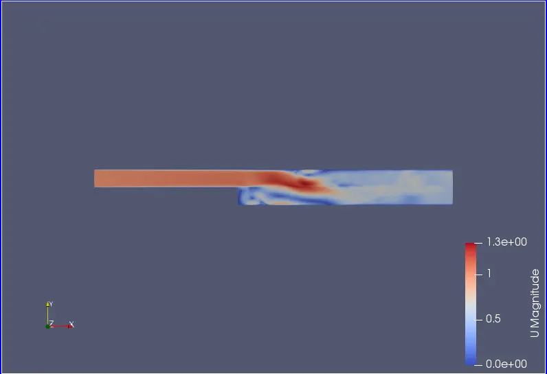
Fig(f) Grading factor =0.2
The above fig(e) and fig(f) shows that the change in velocity of a fluid when flows through a backward facing step channel. In these figures it is clear that the mesh with a grading factor of 0.2 produces a more accurate and finer result when compare to that of a mesh produced by simple grading(G.F = 1). The change in velocity with respected to the timestep when a fluid flows through a backward facing step channel is ploted at a distance of 0.085m from inlet as shown below in fig(g) and fig(h). whereas x axis denotes the time step and y axis denotes the velocity.
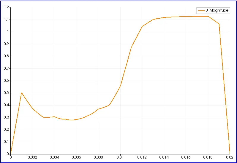
Fig(g) simple grading(G.F = 1)
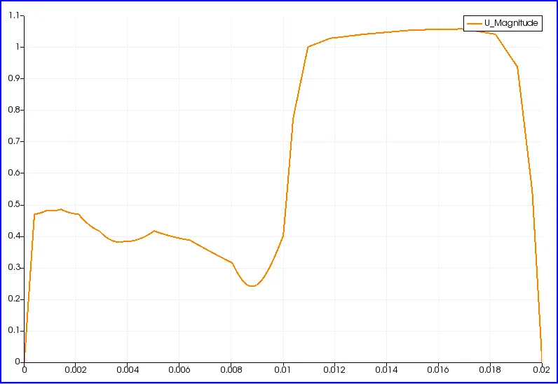
Fig(h) Grading factor =0.2
Change in pressure :
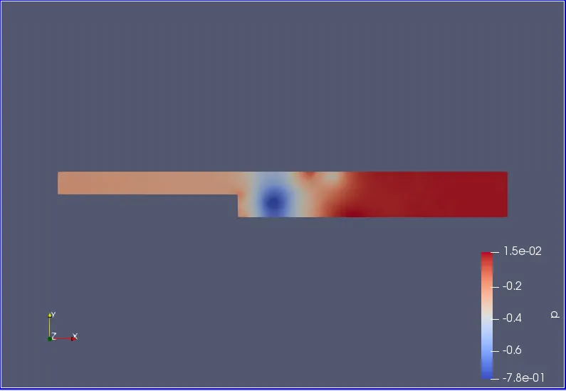
Fig(i) simple grading(G.F = 1)
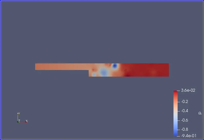
Fig(j) Grading factor =0.2
The above fig(i) and fig(j) shows that the change in pressure of a fluid when flows through a backward facing step channel. In these figures it is clear that the mesh with a grading factor of 0.2 produces a more accurate and finer result when compare to that of a mesh produced by simple grading(G.F = 1). The change in velocity with respected to the timestep when a fluid flows through a backward facing step channel is ploted at a distance of 0.085m from inlet as shown below in fig(k) and fig(l). whereas x axis denotes the time step and y axis denotes the pressure.
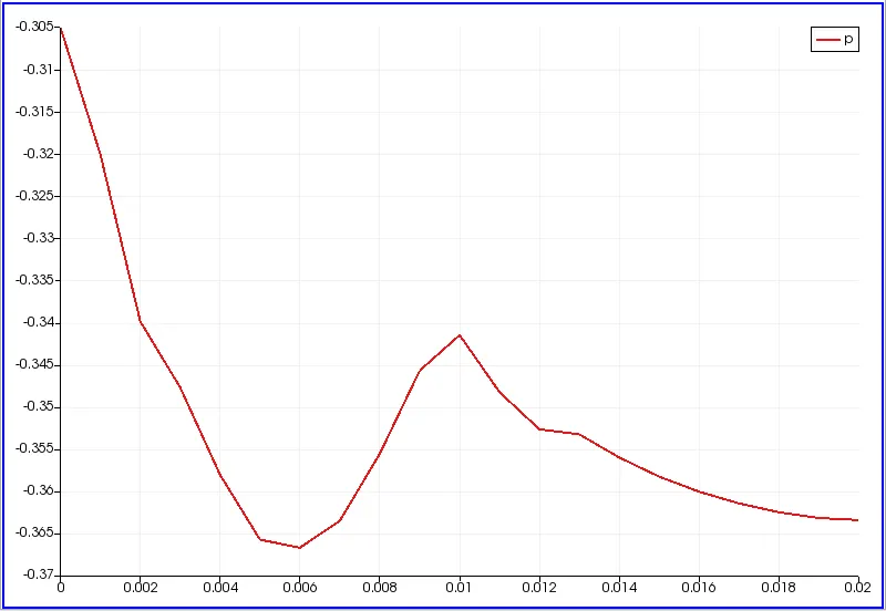
Fig(k) simple grading(G.F = 1)
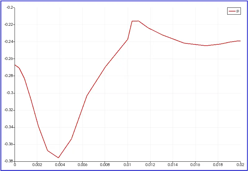
Fig(l) Grading factor =0.2
Conclusion :
- Simulate of an incompressible-laminar-viscous flow through the backward facing step geometry is successfully compiled and the results are ploted and discussed at the output.
- From the above discussion we can say that grading factor was the necessary condition in order to produce the accurate result. smaller the size of a meshgrid more will be the compuational time but we can able to produce accurante results.