Week 8 - Simulation of a backward facing step in OpenFOAM
OBJECTIVE :
to simulate an incompressible-laminar-viscous flow through the backward-facing step geometry. You should perform a transient simulation. The solver can be chosen based on the described physics of the flow. You need to explain the entire simulation procedure (how you set up the case). You should also provide explanations for every change you make inside the reference case files obtained from OpenFOAM tutorials. You can choose the inlet velocity such that the flow is laminar.
After that, you will perform 2 case studies as described below and compare the results.
Case 1 - Simulate the flow without using any grading factor (i.e., GF = 1)
Case 2 - Simulate the flow with a grading factor of 0.2. The cells should be finer near the walls (including the step wall).
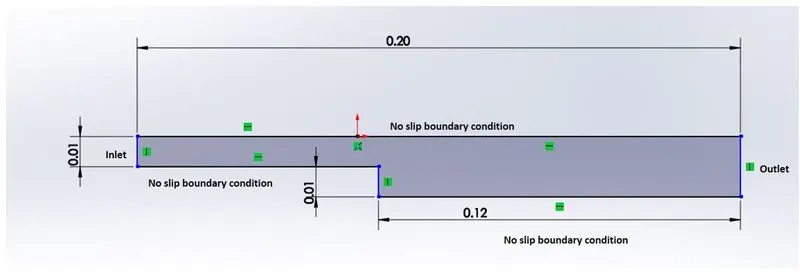
THEORY :
In this simulation, we have to simulate for incompressible-laminar-viscous flow, this means during the flow the density of the flowing fluid is constant throughout the flow and the flow is regular and has no mixing of flows that is the pathlines do not interact with each other since it is a laminar flow and we need to take friction between the wall and the fluid into account since it is a viscous flow.
by 'Reynolds number ' we can determine whether a flow is laminar or turbulent re<2300 the flow is characterized as laminar. if 2300<re<3000 then the flow is in a transitional state and if re>3000 the flow is turbulent.
PROCEDURE :
- First, open the tutorial files in OpenFOAM using the command 'tut' and go to the 'incompressible' folder and then 'icoFoam' and copy the cavity folder into the run folder (which is created by the user).
- now navigate to the run folder, and open the cavity folder inside the 'cavity' folder there will be another 'cavity' folder open that after opening it there will be the system folder this folder has the information about our mesh, simulation time, and schemes and methods to solve our problem will be in this folder
- open 'blockMeshDict' using gedit command and after that enter all vertices of our mesh in and form a block using hex in that text file with the required number of cells and after that specify our boundary in the mesh here we should be careful because we will be entering the face of a block as our boundary (ie inlet, outlet, etc) it should be specified in such a way that it should obey the right-hand coordinate system and save the 'blockMeshDict' file
- now open the 'controlDict' file using gedit change the end time as 4 and deltaT as 1e-3 and writeInterval as 20 this will be explained later
- now navigate back to the cavity folder where we can find the '0' folder which contains our boundary condition that is velocity, pressure at inlets and outlets there will be two files named 'p' and 'U' which is pressure and velocity respectively now open 'p ' using 'gedit' now change the boundaries name according to blockMeshDict and entry it into the boundaryField and set interalField as uniform 0, and an inlet set, it as zeroGradient and in outlet see it as fixedValue as uniform 0 and now open 'U' file and also make changes in boundaryField according to blockMeshDict and set inlet velocity as (0.05,0,0) and outlet as zeroGradient , and top and bottom face 'noslip' since there is no-slip condition. and front and back face as 'empty'
- after that navigate back to the cavity and now open the constant folder where we can see 'transportProperties' open using gedit and after that between the last two comments lines delete the existing one and write 'transportModel Newtonin' and below that 'nu [0 2 -1 0 0 0 0] 0.01' this is kinematic viscosity.
- after that in the command window type 'blockMesh' now our mesh is ready and after that type 'icoFoam' and then our simulation is done to view it we need to open ParaView for that the command is 'paraFoam'
icoFoam:
this solver has been chosen because icoFoam uses the PISO algorithm to solve the continuity equation and also it is one of the best solvers for incompressible flow
note: to capture the fluid flow we need to give a velocity, and to determine the correct velocity we need to take the length of the geometry which is 0.2 meters so we need to assume a velocity which is below 0.2 otherwise we need to increase the time step more which leads to increase in total simulation time. and the simulation that needs to do is determined by `speed =(distance)/(time)` now let's assume our fluid velocity is 0.05 m/s then 0.05/0.2=4sec which is our simulation time
blockMeshDict for simple grinding 1:
/*--------------------------------*- C++ -*----------------------------------*\
  =========                 |
  \\      /  F ield         | OpenFOAM: The Open Source CFD Toolbox
   \\    /   O peration     | Website:  https://openfoam.org
    \\  /    A nd           | Version:  8
     \\/     M anipulation  |
\*---------------------------------------------------------------------------*/
FoamFile
{
    version     2.0;
    format      ascii;
    class       dictionary;
    object      blockMeshDict;
}
// * * * * * * * * * * * * * * * * * * * * * * * * * * * * * * * * * * * * * //

convertToMeters 0.01;

vertices
(
    (0 0 0)
    (8 0 0)
    (8 0.5 0)
    (0 0.5 0)
    (8 1 0)
    (0 1 0)
    (20 1 0)
    (20 0.5 0)
    (20 0 0)
    (20 -1 0)
    (8 -1 0)

    (0 0 0.1)
    (8 0 0.1)
    (8 0.5 0.1)
    (0 0.5 0.1)
    (8 1 0.1)
    (0 1 0.1)
    (20 1 0.1)
    (20 0.5 0.1)
    (20 0 0.1)
    (20 -1 0.1)
    (8 -1 0.1)
);

blocks
(
    hex (0 1 2 3 11 12 13 14) (120 5 1) simpleGrading (1 1 1)
    hex (3 2 4 5 14 13 15 16) (120 5 1) simpleGrading (1 1 1)
    hex (2 7 6 4 13 18 17 15) (80 5 1) simpleGrading (1 1 1)
    hex (1 8 7 2 12 19 18 13) (80 5 1) simpleGrading (1 1 1)
    hex (10 9 8 1 21 20 19 12) (80 10 1) simpleGrading (1 1 1)

);

edges
(
);

boundary
(
 inlet
    {
        type patch;
        faces
        (
            (0 11 14 3)
            (3 14 16 5)
        );
    }
    outlet
    {
        type patch;
        faces
        (

            (19 8 7 18)
            (18 7 6 17)
            (20 9 8 19)
        );
    }
    frontAndBack
    {
        type empty;
        faces
        (
            (1 0 3 2)
            (11 12 13 14)
            (3 2 4 5)
            (14 13 15 16)
            (7 2 4 6)
            (13 18 17 15)
            (8 1 2 7)
            (12 19 18 13)
            (9 10 1 8)
            (21 20 19 12)
        );
    }
    NO_SLIP_WALL
    {
    type wall;
    faces
    (
         (16 15 4 5)
         (15 17 6 4)
         (12 11 0 1)
         (20 21 10 9)
         (10 21 12 1)
    );
    }

);

mergePatchPairs
(
);

// ************************************************************************* //
controlDict:
/*--------------------------------*- C++ -*----------------------------------*\
  =========                 |
  \\      /  F ield         | OpenFOAM: The Open Source CFD Toolbox
   \\    /   O peration     | Website:  https://openfoam.org
    \\  /    A nd           | Version:  8
     \\/     M anipulation  |
\*---------------------------------------------------------------------------*/
FoamFile
{
    version     2.0;
    format      ascii;
    class       dictionary;
    location    "system";
    object      controlDict;
}
// * * * * * * * * * * * * * * * * * * * * * * * * * * * * * * * * * * * * * //

application     icoFoam;

startFrom       startTime;

startTime       0;

stopAt          endTime;

endTime         4;

deltaT          1e-3;

writeControl    timeStep;

writeInterval   20;

purgeWrite      0;

writeFormat     ascii;

writePrecision  6;

writeCompression off;

timeFormat      general;

timePrecision   6;

runTimeModifiable true;


// ************************************************************************* //
velocity (U);
/*--------------------------------*- C++ -*----------------------------------*\
  =========                 |
  \\      /  F ield         | OpenFOAM: The Open Source CFD Toolbox
   \\    /   O peration     | Website:  https://openfoam.org
    \\  /    A nd           | Version:  8
     \\/     M anipulation  |
\*---------------------------------------------------------------------------*/
FoamFile
{
    version     2.0;
    format      ascii;
    class       volVectorField;
    object      U;
}
// * * * * * * * * * * * * * * * * * * * * * * * * * * * * * * * * * * * * * //

dimensions      [0 1 -1 0 0 0 0];

internalField   uniform (0 0 0);

boundaryField
{
    inlet
    {
        type            fixedValue;
        value           uniform (0.05 0 0);
    }

    outlet
    {
        type            zeroGradient;
    }

    frontAndBack
    {
        type            empty;
    }

    NO_SLIP_WALL
    {
        type            noSlip;
    }
}

// ************************************************************************* //
pressure P
/*--------------------------------*- C++ -*----------------------------------*\
  =========                 |
  \\      /  F ield         | OpenFOAM: The Open Source CFD Toolbox
   \\    /   O peration     | Website:  https://openfoam.org
    \\  /    A nd           | Version:  8
     \\/     M anipulation  |
\*---------------------------------------------------------------------------*/
FoamFile
{
    version     2.0;
    format      ascii;
    class       volScalarField;
    object      p;
}
// * * * * * * * * * * * * * * * * * * * * * * * * * * * * * * * * * * * * * //

dimensions      [0 2 -2 0 0 0 0];

internalField   uniform 0;

boundaryField
{
    inlet
    {
        type            zeroGradient;

    }

    outlet
    {
        type            fixedValue;
        value           uniform 0;
    }

    frontAndBack
    {
        type            empty;
    }

    NO_SLIP_WALL
    {
        type            zeroGradient;
    }
}

// ************************************************************************* //
transportproperties:
/*--------------------------------*- C++ -*----------------------------------*\
  =========                 |
  \\      /  F ield         | OpenFOAM: The Open Source CFD Toolbox
   \\    /   O peration     | Website:  https://openfoam.org
    \\  /    A nd           | Version:  8
     \\/     M anipulation  |
\*---------------------------------------------------------------------------*/
FoamFile
{
    version     2.0;
    format      ascii;
    class       dictionary;
    location    "constant";
    object      transportProperties;
}
// * * * * * * * * * * * * * * * * * * * * * * * * * * * * * * * * * * * * * //
transportModel Newtonian;

nu             [0 2 -1 0 0 0 0] 0.01;


// ************************************************************************* //
blockMeshDict for different grading factors to get finer mesh:
/*--------------------------------*- C++ -*----------------------------------*\
  =========                 |
  \\      /  F ield         | OpenFOAM: The Open Source CFD Toolbox
   \\    /   O peration     | Website:  https://openfoam.org
    \\  /    A nd           | Version:  8
     \\/     M anipulation  |
\*---------------------------------------------------------------------------*/
FoamFile
{
    version     2.0;
    format      ascii;
    class       dictionary;
    object      blockMeshDict;
}
// * * * * * * * * * * * * * * * * * * * * * * * * * * * * * * * * * * * * * //

convertToMeters 0.01;

vertices
(
    (0 0 0)
    (8 0 0)
    (8 0.5 0)
    (0 0.5 0)
    (8 1 0)
    (0 1 0)
    (20 1 0)
    (20 0.5 0)
    (20 0 0)
    (20 -1 0)
    (8 -1 0)

    (0 0 0.1)
    (8 0 0.1)
    (8 0.5 0.1)
    (0 0.5 0.1)
    (8 1 0.1)
    (0 1 0.1)
    (20 1 0.1)
    (20 0.5 0.1)
    (20 0 0.1)
    (20 -1 0.1)
    (8 -1 0.1)
);

blocks
(
    hex (0 1 2 3 11 12 13 14) (120 5 1) simpleGrading (1 20 1)
    hex (3 2 4 5 14 13 15 16) (120 5 1) simpleGrading (1 0.2 1)
    hex (2 7 6 4 13 18 17 15) (80 5 1) simpleGrading (1 0.2 1)
    hex (1 8 7 2 12 19 18 13) (80 5 1) simpleGrading (1 20 1)
    hex (10 9 8 1 21 20 19 12) (80 10 1) simpleGrading (1 1 1)

);

edges
(
);

boundary
(
 inlet
    {
        type patch;
        faces
        (
            (0 11 14 3)
            (3 14 16 5)
        );
    }
    outlet
    {
        type patch;
        faces
        (

            (19 8 7 18)
            (18 7 6 17)
            (20 9 8 19)
        );
    }
    frontAndBack
    {
        type empty;
        faces
        (
            (1 0 3 2)
            (11 12 13 14)
            (3 2 4 5)
            (14 13 15 16)
            (7 2 4 6)
            (13 18 17 15)
            (8 1 2 7)
            (12 19 18 13)
            (9 10 1 8)
            (21 20 19 12)
        );
    }
    NO_SLIP_WALL
    {
    type wall;
    faces
    (
         (16 15 4 5)
         (15 17 6 4)
         (12 11 0 1)
         (20 21 10 9)
         (10 21 12 1)
    );
    }

);

mergePatchPairs
(
);

// ************************************************************************* //
here we did a simple grading that is making the mesh finer by introducing a grading factor this means, let us take the example of the first block in the Dict file the first ' hex (0 1 2 3 11 12 13 14) (120 5 1) simpleGrading (1 20 1) ' we have 5 cells in the y-axis and simple grading of 20 means in y-direction `(lasstcell)/(firstcell)=20` this tells that last cell in the y-direction is 20 times the size of the first cell in the x-direction so the cell along the wall(in the first block) is finer. this grading should be done such that the cell should have a consistent arrangement otherwise we will face an error.
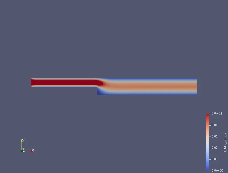
simulation by grading factor 1:
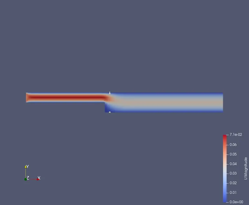
simulation by different grading factor 0.2:
Discussion about the above simulation :
As we can see in the inlet of the mesh with a grading factor of 0.2 is a bit more colorful than the inlet of mesh with a grading factor of 1 . and after the backward step, we can see the average velocity in the midsection of the mesh. so by comparing this we can able see the boundary layer. after increasing the number of cells in the walls of the mesh we can capture a bit more accurately for the same condition (U,p, rho, nu).
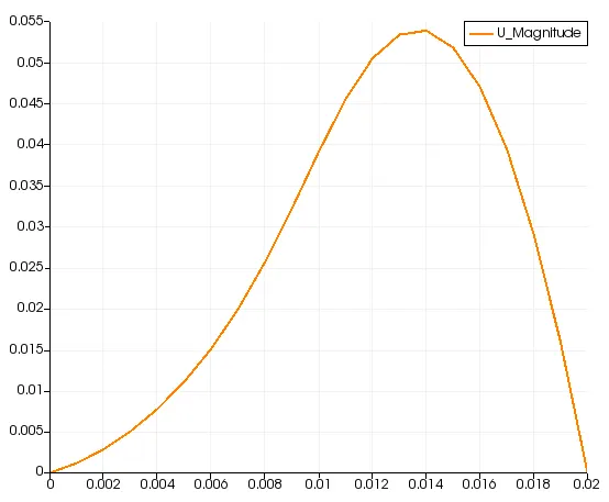
plot over a line for mesh with grading factor 1:
plot over a line for mesh with grading factor 0.2 :
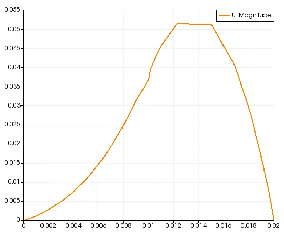
discussion of the above plot :
after analyzing the above plot we can say that the velocity up to 0.1 is y-direction (in the mesh) is the same because there is no flow separation but after 0.1 there is flow separation so the velocity curve should not be smooth but it is in the plot where grading factor is 1 but as we see in the plot which has grading factor as 0.2 we can able to see some disturbance in the velocity the backward step.
the finer mesh can yield an accurate result than coarse mesh this fine mesh is achieved by grading