Week 8 - Simulation of a backward facing step in OpenFOAM
To simulate an incompressible-laminar-viscous flow through the backward facing step geometry.
We should perform a transient simulation. The solver can be chosen based on the described physics of the flow.
Here based on the decribed physics of the flow we have chosen icoFoam solver.
After that, you will perform 2 case studies as described below and compare the results.
Case 1 - Simulate the flow without using any grading factor (i.e., GF = 1)
Case 2 - Simulate the flow with grading factor of 0.2. The cells should be finer near the walls (includig the step wall).
You can use the following mesh parameters but you can feel free to modify these values.
Mesh specification
- Number of cells along the x direction (longer dimension) = 200
- Number of cells along the longer y direction = 20;
The typical approach adopted to performing numerical simulation in OpenFOAM involves the following steps:
- Identifying the tutorial in the 'FOAM_TUTORIALS' folder that contains the appropriate governing equations relevant to the physics of the flow for the given problem. A typical file structure of an OpenFOAM tutorial consists of the below mentioned directories and files:
- A 'system' directory with the 'controlDict', 'fvSchemes' and 'fvSolution' files used for specifying the numerical schemes and solution procedure along with control on the simulation run properties. Additionally, for the given numerical problem, a file by the name 'blockMeshDict' mentions the creation of different blocks representing the geometry as well as its mesh properties.
- A 'constant' directory that contains a 'polyMesh' directory outlining the various aspects of the mesh such as 'boundary', 'points', 'faces', etc., and a file that defines the physical properties, in this case, 'transportProperties' specifying the value of kinematic viscosity.
- A time directory, usually called the '0' directory that consists of files representing the different fields or fluid flow properties with values as required at the start of simulation run or at time t=0">t=0t=0.
- Copying the now identified tutorial folder from the 'FOAM_TUTORIALS' folder to the 'FOAM_RUN' folder, specifically created to allow simulation run of OpenFOAM numerical simulation cases, with either the same name or preferably a name relevant to the geometry to be discretized.
- Replacing the geometry and boundary list of the pre-existing tutorial with the geometry and boundary list pertaining to the given problem and defining mesh parameters with regards to the flow physics, in this case by updating the 'blockMeshDict' file (Section 2.1 Modelling).
- Updating the fields' files present inside the '0' directory viz., 'U' and 'p', with the boundary list as specified in the 'blockMeshDict' file and appropriate values at the relevant boundary to ensure the given numerical problem has the right boundary conditions and that the solution would be correctly initialised (Section 2.2 Boundary Conditions).
- Updating the 'controlDict' file, in this case the 'deltaT' and 'endTime' parameters with values that take into consideration domain specific attributes such as length of the domain in the direction of flow, fluid flow velocity and avoiding violation of Courant-Friedrichs-Lewy Condition or the CFL number by limiting its mean and maximum value during simulation run below 1 (Section 2.4 Determination of transient parameters).
Boundary condition specification
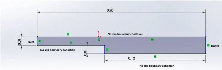
The domain specifications are provided in the following figure.
|
To create the geometry as shown in the figure, we need edit the blockMeshDict file that is available in the system folder of the case setup. Geometry Creation: Let us consider creating the geometry using 5 blocks as shown in the figure below, NOTE: We have demonstrated the geometry creation using 5 blocks and have indexed the vertices this way. This can be varied, according to your comfort. The Isometric View, Now let’s, start indexing the Vertices on the Back side of the Blocks, Since openFoam uses C++ programming, we start the index from “0”. (The Numbering of the vertices can be varied according to your comfort) Similarly, the indexing for the frontside of the Blocks are, To View the Bigger Picture, Finally, to define the blocks, we need to specify the right order of vertex indices For example: to create the 1st Block for this case, hex (0 1 2 3 11 12 13 14) (1 1 1) simpleGrading (1 1 1) Similarly proceed by defining the vertices of the other blocks in the Geometry. To View geometry that you have created, clear out all the entries inside the boundary section of the blockMeshDict file and execute the blockMesh command in the terminal. Now open paraview and view the geometry that you have created. Meshing: Now to mesh the geometry fill in the number of cells in x, y and z direction inside the second parenthesis of the Hex command, i.e., hex(0 1 2 3 11 12 13 14) (10 10 1) simplegrading(1 1 1). since this is a 2D problem, increasing the number of cells in the z direction, doesn’t make sense. To view the mesh in paraFoam, select the surface with edges option and view the mesh. Similarly to refine the mesh near the walls of the geometry, you need to play around with the numbers in the third parenthesis. We leave that for you to figure out, how It can be done. Boundary Conditions: Before we run the simulations, we need to specify the initial and boundary conditions. The given boundary conditions are, 1.Inlet: (Type patch) The faces that contribute to inlet boundary are shown above. If we are looking at these faces from the outside, the definition of inlet boundary will be in counter-clockwise direction, (0 11 14 3) (3 14 16 5) 2.Outlet: (Type patch) Similarly, we have 3 faces contributing to the outlet boundary condition. Since we are viewing the faces from outside, hence the definition of the outlet boundary will be in counter-clockwise direction, (9 8 19 20) (8 7 18 19) (7 6 17 18) Now for the other boundary look at the images below and repeat the steps to define the boundaries. 3.Front & Back: (Type empty) 4.No Slip walls: (Type wall) After defining the boundaries correctly, to check if you have given defined them correctly, execute the blockMesh command in the terminal.Now open paraFoam, select all the patches and click apply. You will now be able to see the boundary conditions that have been applied to the geometry. As part of the Challenge, figure out the right initial conditions. |
Case 1 - Simulate the flow without using any grading factor (i.e., GF = 1).
BlockMeshDict:
/*--------------------------------*- C++ -*----------------------------------*
  =========                 |
  \      /  F ield         | OpenFOAM: The Open Source CFD Toolbox
   \    /   O peration     | Website:  https://openfoam.org
    \  /    A nd           | Version:  8
     \/     M anipulation  |
*---------------------------------------------------------------------------*/
FoamFile
{
    version     2.0;
    format      ascii;
    class       dictionary;
    object      blockMeshDict;
}
// * * * * * * * * * * * * * * * * * * * * * * * * * * * * * * * * * * * * * //

convertToMeters 0.1;

vertices
(
    (0 0 0)
    (8 0 0)
    (8 0.5 0)
    (0 0.5 0)
    (8 1 0)
    (0 1 0)
    (20 1 0)
    (20 0.5 0)
    (20 0 0)
    (20 -1 0)
    (8 -1 0)
    (0 0 0.1)
    (8 0 0.1)
    (8 0.5 0.1)
    (0 0.5 0.1)
    (8 1 0.1)
    (0 1 0.1)
    (20 1 0.1)
    (20 0.5 0.1)
    (20 0 0.1)
    (20 -1 0.1)
    (8 -1 0.1)
 );

blocks
(
    hex (0 1 2 3 11 12 13 14) (80 5 1) simpleGrading (1 1 1)
    hex (3 2 4 5 14 13 15 16) (80 5 1) simpleGrading (1 1 1)
    hex (10 9 8 1 21 20 19 12) (120 10 1) simpleGrading (1 1 1)
    hex (1 8 7 2 12 19 18 13) (120 5 1) simpleGrading (1 1 1)
    hex (2 7 6 4 13 18 17 15) (120 5 1) simpleGrading (1 1 1)
 );

edges
(
);

boundary
(
    inlet
    {
        type patch;
        faces
        (
            (0 11 14 3)
            (3 14 16 5)
        );
    }
    outlet
    {
        type patch;
        faces
        (
            (9 8 19 20)
            (8 7 18 19)
            (7 6 17 18)
        );
    }
    frontAndBack
    {
        type empty;
        faces
        (
            (0 3 2 1)
            (3 5 4 2)
            (10 1 8 9)
            (1 2 7 8)
            (2 4 6 7)
            (11 12 13 14)
            (14 13 15 16)
            (21 20 19 12)
            (12 19 18 13)
            (13 18 17 15)
        );
    }
    noslipwalls
    {
        type wall;
        faces
        (
            (5 16 15 4)
            (4 15 17 6)
            (10 21 12 1)
            (0 1 12 11)
            (10 9 20 21)
        );
    }
);

mergePatchPairs
(
);

// ************************************************************************* //
ControlDict:
/*--------------------------------*- C++ -*----------------------------------*
  =========                 |
  \      /  F ield         | OpenFOAM: The Open Source CFD Toolbox
   \    /   O peration     | Website:  https://openfoam.org
    \  /    A nd           | Version:  8
     \/     M anipulation  |
*---------------------------------------------------------------------------*/
FoamFile
{
    version     2.0;
    format      ascii;
    class       dictionary;
    location    "system";
    object      controlDict;
}
// * * * * * * * * * * * * * * * * * * * * * * * * * * * * * * * * * * * * * //

application     icoFoam;

startFrom       startTime;

startTime       0;

stopAt          endTime;

endTime         0.5;

deltaT          0.001;

writeControl    timeStep;

writeInterval   20;

purgeWrite      0;

writeFormat     ascii;

writePrecision  6;

writeCompression off;

timeFormat      general;

timePrecision   6;

runTimeModifiable true;


// ************************************************************************* //
Here i have given step time =0.001 to satsify courant number condition.
Velocity file:
/*--------------------------------*- C++ -*----------------------------------*
  =========                 |
  \      /  F ield         | OpenFOAM: The Open Source CFD Toolbox
   \    /   O peration     | Website:  https://openfoam.org
    \  /    A nd           | Version:  8
     \/     M anipulation  |
*---------------------------------------------------------------------------*/
FoamFile
{
    version     2.0;
    format      ascii;
    class       volVectorField;
    object      U;
}
// * * * * * * * * * * * * * * * * * * * * * * * * * * * * * * * * * * * * * //

dimensions      [0 1 -1 0 0 0 0];

internalField   uniform (0 0 0);

boundaryField
{
    inlet
    {
        type            fixedValue;
        value           uniform (1 0 0);
    }

    outlet
    {
        type            zeroGradient;
    }
    noslipwalls
    {
        type           noSlip;
    }
    frontAndBack
    {
        type            empty;
    }
}

// ************************************************************************* //
Pressure file:
/*--------------------------------*- C++ -*----------------------------------*
  =========                 |
  \      /  F ield         | OpenFOAM: The Open Source CFD Toolbox
   \    /   O peration     | Website:  https://openfoam.org
    \  /    A nd           | Version:  8
     \/     M anipulation  |
*---------------------------------------------------------------------------*/
FoamFile
{
    version     2.0;
    format      ascii;
    class       volScalarField;
    object      p;
}
// * * * * * * * * * * * * * * * * * * * * * * * * * * * * * * * * * * * * * //

dimensions      [0 2 -2 0 0 0 0];

internalField   uniform 0;

boundaryField
{
    inlet
    {
        type            zeroGradient;
    }

    outlet
    {
        type            fixedValue;
        value            uniform 0;
    }
    noslipwalls
    {
        type            zeroGradient;
    }
    frontAndBack
    {
        type            empty;
    }

}

// ************************************************************************* //
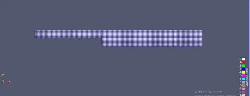
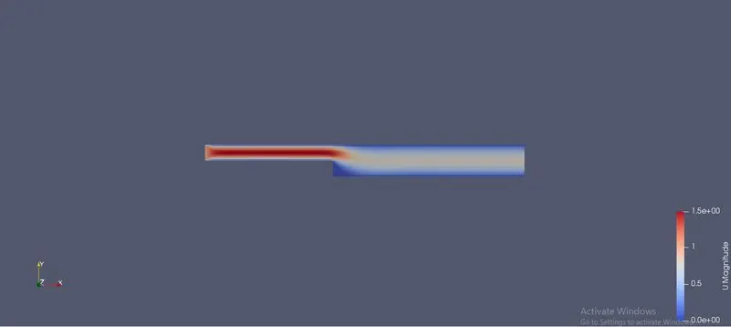
Plots that we get from the above simulation:
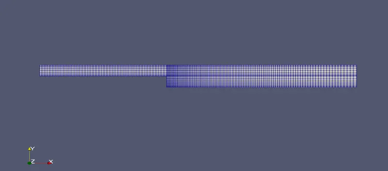
Surfacewithedges:
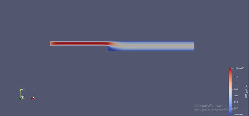
Velocity profile:
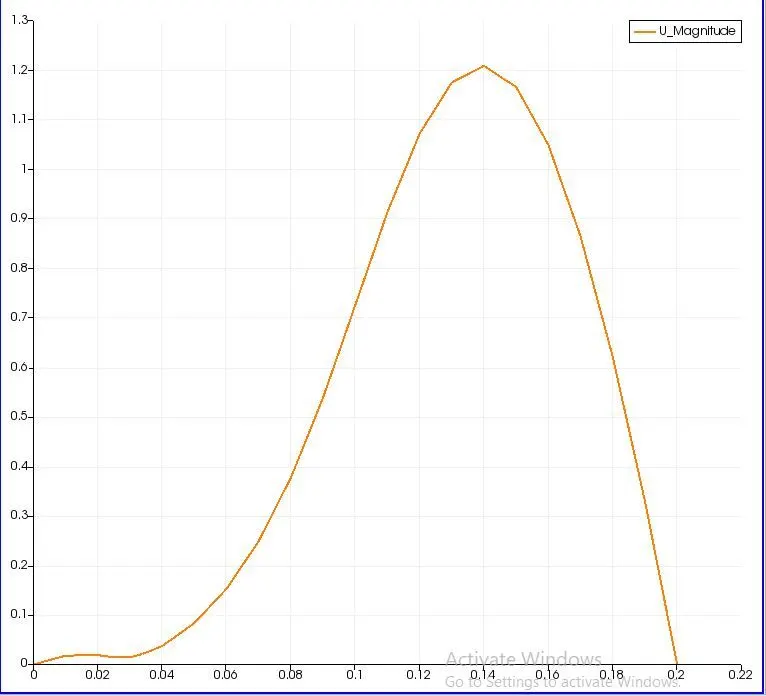
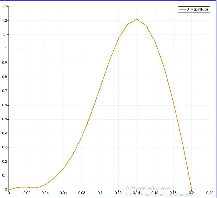
Velocity plot:
Case 2 - Simulate the flow with grading factor of 0.2.
Here we have to alter the blockmeshdict block:
BlockMeshDict:
/*--------------------------------*- C++ -*----------------------------------*
  =========                 |
  \      /  F ield         | OpenFOAM: The Open Source CFD Toolbox
   \    /   O peration     | Website:  https://openfoam.org
    \  /    A nd           | Version:  8
     \/     M anipulation  |
*---------------------------------------------------------------------------*/
FoamFile
{
    version     2.0;
    format      ascii;
    class       dictionary;
    object      blockMeshDict;
}
// * * * * * * * * * * * * * * * * * * * * * * * * * * * * * * * * * * * * * //

convertToMeters 0.1;

vertices
(
    (0 0 0)
    (8 0 0)
    (8 0.5 0)
    (0 0.5 0)
    (8 1 0)
    (0 1 0)
    (20 1 0)
    (20 0.5 0)
    (20 0 0)
    (20 -1 0)
    (8 -1 0)
    (0 0 0.1)
    (8 0 0.1)
    (8 0.5 0.1)
    (0 0.5 0.1)
    (8 1 0.1)
    (0 1 0.1)
    (20 1 0.1)
    (20 0.5 0.1)
    (20 0 0.1)
    (20 -1 0.1)
    (8 -1 0.1)
 );

blocks
(
    hex (0 1 2 3 11 12 13 14) (80 5 1) simpleGrading (1 5 1)
    hex (3 2 4 5 14 13 15 16) (80 5 1) simpleGrading (1 0.2 1)
    hex (2 7 6 4 13 18 17 15) (120 5 1) simpleGrading (5 0.2 1)
    hex (10 9 8 1 21 20 19 12) (120 10 1) simpleGrading (5 5 1)
    hex (1 8 7 2 12 19 18 13) (120 5 1) simpleGrading (5 5 1)

 );

edges
(
);

boundary
(
    inlet
    {
        type patch;
        faces
        (
            (0 11 14 3)
            (3 14 16 5)
        );
    }
    outlet
    {
        type patch;
        faces
        (
            (9 8 19 20)
            (8 7 18 19)
            (7 6 17 18)
        );
    }
    frontAndBack
    {
        type empty;
        faces
        (
            (0 3 2 1)
            (3 5 4 2)
            (10 1 8 9)
            (1 2 7 8)
            (2 4 6 7)
            (11 12 13 14)
            (14 13 15 16)
            (21 20 19 12)
            (12 19 18 13)
            (13 18 17 15)
        );
    }
    noslipwalls
    {
        type wall;
        faces
        (
            (5 16 15 4)
            (4 15 17 6)
            (10 21 12 1)
            (0 1 12 11)
            (10 9 20 21)
        );
    }
);

mergePatchPairs
(
);

// ************************************************************************* //
Controldict:
/*--------------------------------*- C++ -*----------------------------------*
  =========                 |
  \      /  F ield         | OpenFOAM: The Open Source CFD Toolbox
   \    /   O peration     | Website:  https://openfoam.org
    \  /    A nd           | Version:  8
     \/     M anipulation  |
*---------------------------------------------------------------------------*/
FoamFile
{
    version     2.0;
    format      ascii;
    class       dictionary;
    location    "system";
    object      controlDict;
}
// * * * * * * * * * * * * * * * * * * * * * * * * * * * * * * * * * * * * * //

application     icoFoam;

startFrom       startTime;

startTime       0;

stopAt          endTime;

endTime         0.5;

deltaT          0.001;

writeControl    timeStep;

writeInterval   20;

purgeWrite      0;

writeFormat     ascii;

writePrecision  6;

writeCompression off;

timeFormat      general;

timePrecision   6;

runTimeModifiable true;


// ************************************************************************* //
Velocity file:
/*--------------------------------*- C++ -*----------------------------------*
  =========                 |
  \      /  F ield         | OpenFOAM: The Open Source CFD Toolbox
   \    /   O peration     | Website:  https://openfoam.org
    \  /    A nd           | Version:  8
     \/     M anipulation  |
*---------------------------------------------------------------------------*/
FoamFile
{
    version     2.0;
    format      ascii;
    class       volVectorField;
    object      U;
}
// * * * * * * * * * * * * * * * * * * * * * * * * * * * * * * * * * * * * * //

dimensions      [0 1 -1 0 0 0 0];

internalField   uniform (0 0 0);

boundaryField
{
    inlet
    {
        type            fixedValue;
        value           uniform (1 0 0);
    }

    outlet
    {
        type            zeroGradient;
    }
    noslipwalls
    {
        type           noSlip;
    }
    frontAndBack
    {
        type            empty;
    }
}

// ************************************************************************* //
Pressure file:
/*--------------------------------*- C++ -*----------------------------------*
  =========                 |
  \      /  F ield         | OpenFOAM: The Open Source CFD Toolbox
   \    /   O peration     | Website:  https://openfoam.org
    \  /    A nd           | Version:  8
     \/     M anipulation  |
*---------------------------------------------------------------------------*/
FoamFile
{
    version     2.0;
    format      ascii;
    class       volScalarField;
    object      p;
}
// * * * * * * * * * * * * * * * * * * * * * * * * * * * * * * * * * * * * * //

dimensions      [0 2 -2 0 0 0 0];

internalField   uniform 0;

boundaryField
{
    inlet
    {
        type            zeroGradient;
    }

    outlet
    {
        type            fixedValue;
        value            uniform 0;
    }
    noslipwalls
    {
        type            zeroGradient;
    }
    frontAndBack
    {
        type            empty;
    }

}

// ************************************************************************* //
Plots that we get from the above simulation:
surfacewithedges:
Velocity profile:
Velocity plot:
comparing
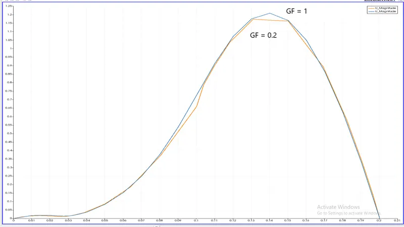
two different meshes indicates the significance of grading/growth factor as the mesh without any grading factor (GF = 1) was not refined enough to capture the near wall gradients of the flow properties, especially velocity, as compared to the mesh using a grading factor of 0.2 in the relevant blocks of the decomposed domain.
Conclusion:
By changing the simple grading factor from the value of 1 to 0.2 the mesh becomes finer at walls and the solution becomes very accurate.
From the graph it can be seen that the velocity in two cases are same that is 1.2 m/s at distance of 0.085 from the inlet in x-axis.
Overall the change in the size of simple grading factor (mesh size) the results remains the same as approximately.