Week 8 - Simulation of a backward facing step in OpenFOAM
AIM
In this challenge, you are going to simulate an incompressible-laminar-viscous flow through the backward facing step geometry. You should perform a transient simulation. The solver can be chosen based on the described physics of the flow. You need to explain the entire simulation procedure (how you set up the case). You should also provide explanations to every change you make inside the reference case files obtained from OpenFOAM tutorials. You can choose the inlet velocity shuch that the flow is laminar.
After that, perform 2 case studies as described below and compare the results.
Case 1 - Simulate the flow without using any grading factor (i.e., GF = 1)
Case 2 - Simulate the flow with grading factor of 0.2. The cells should be finer near the walls (includig the step wall).
Mesh specification
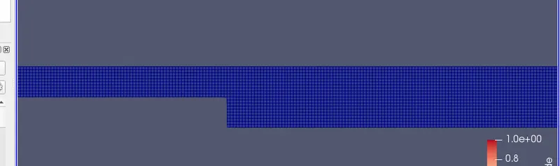
- Number of cells along the x direction (longer dimension) = 200
- Number of cells along the longer y direction = 20;
Boundary condition specification
The domain specifications are provided in the following figure.
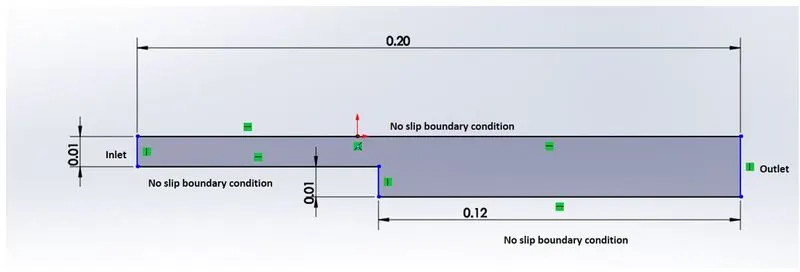
- Measure the velocity profile at 0.085 m from the inlet of the geometry for both case studies and compare. You can use the plot over line tool for this.
- Explain why Grading/Growth factor is essential for meshing.
icoFoam solver
icoFoam solves the incompressible laminar Navier-Stokes equations using the PISO algorithm. The code is inherently transient, requiring an initial condition (such as zero velocity) and boundary conditions. The icoFOAM code can take mesh non-orthogonality into account with successive non-orthogonality iterations. The number of PISO corrections and non-orthogonality corrections are controlled through user input.
Simulation procedure
- Open a new terminal by clicking ctrl+alt+t
- Type 'tut' to open openfoam tutorial directory, type 'ls' to view the list of tutorials.
- select incompressible by typing 'cd incompressible', since we are dealing with incompressible flow (select a folder by typing 'cd foldername') .
- Type 'ls' to view the solvers present in the folder, Choose icoFoam by typing 'cd icoFoam'. We choose icoFoam because it solves incompressible laminar viscous flows.
- Type 'ls' and select the 'cavity' folder. Type 'ls' again and and select the 'cavity' folder. Copy the cavity folder and paste it in the openfoam run folder by typing ' cp -r cavity/ $FOAM_RUN '. (We shouldn't make any changes in the tutorial folder)
- Open the run folder by typing 'cd run' and open 'cavity' folder in it. Then open 'system' folder.
- Find out blockmesh script file to create domain space and provide mesh specification. (Open the script file by typing 'gedit blockMeshDict')
- Then open 'controldict' file to edit start and end time for simulation. (the CFL value should be less than one)
- In the folder '0' set the initial values for pressure and veclocity according to faces of the given domain.
- Use the 'blockMesh' command and then use 'checkMesh' command to check if there is any error in the mesh.
- Now type 'icoFoam' to run the simulation then use paraview to view the results by typing 'paraFoam' command.
Case 1 - Simulate the flow without using any grading factor (i.e., GF = 1)
Edit the script files as shown below;
blockMeshDict
/*--------------------------------*- C++ -*----------------------------------*\
  =========                 |
  \\      /  F ield         | OpenFOAM: The Open Source CFD Toolbox
   \\    /   O peration     | Website:  https://openfoam.org
    \\  /    A nd           | Version:  9
     \\/     M anipulation  |
\*---------------------------------------------------------------------------*/
FoamFile
{
    format      ascii;
    class       dictionary;
    object      blockMeshDict;
}
// * * * * * * * * * * * * * * * * * * * * * * * * * * * * * * * * * * * * * //

convertToMeters 0.01;

vertices
(
    (0 0 0) //0
    (8 0 0) //1
    (8 0.5 0) //2
    (0 0.5 0) //3
    (8 1 0) //4
    (0 1 0) //5
    (20 1 0)//6
    (20 0.5 0) //7
    (20 0 0) //8
    (20 -1 0) //9
    (8 -1 0) //10
    (0 0 0.1) //11
    (8 0 0.1) //12
    (8 0.5 0.1) //13
    (0 0.5 0.1) //14
    (8 1 0.1) //15
    (0 1 0.1) //16
    (20 1 0.1) //17
    (20 0.5 0.1) //18
    (20 0 0.1) //19
    (20 -1 0.1) //20
    (8 -1 0.1) //21
);

blocks
(
    hex (0 1 2 3 11 12 13 14) (80 5 1) simpleGrading (1 1 1)
    hex (3 2 4 5 14 13 15 16) (80 5 1) simpleGrading (1 1 1)
    hex (2 7 6 4 13 18 17 15) (120 5 1) simpleGrading (1 1 1)
    hex (1 8 7 2 12 19 18 13) (120 5 1) simpleGrading (1 1 1)
    hex (10 9 8 1 21 20 19 12) (120 10 1) simpleGrading (1 1 1)
);

edges
(
);

boundary
(
    inlet
    {
        type patch;
        faces
        (
            (0 11 14 3)
            (3 14 16 5)
        );
    }
    outlet
    {
        type patch;
        faces
        (
            (9 8 19 20)
            (8 7 18 19)
            (7 6 17 18)
        );
    }
    fixedWalls
    {
        type wall;
        faces
        (
            (6 4 15 17)
            (4 5 16 15)
            (10 21 12 1)
            (12 11 0 1)
            (20 21 10 9)
        );
    }
    frontAndBack
    {
        type empty;
        faces
        (
            (14 13 15 16)
            (11 12 13 14)
            (21 20 19 12)
            (12 19 18 13)
            (13 18 17 15)
            (5 4 2 3)
            (0 3 2 1)
            (1 8 9 10)
            (2 7 8 1)
            (4 6 7 2)
        );
    }
);

mergePatchPairs
(
);

// ************************************************************************* //
controlDict
/*--------------------------------*- C++ -*----------------------------------*\
  =========                 |
  \\      /  F ield         | OpenFOAM: The Open Source CFD Toolbox
   \\    /   O peration     | Website:  https://openfoam.org
    \\  /    A nd           | Version:  9
     \\/     M anipulation  |
\*---------------------------------------------------------------------------*/
FoamFile
{
    format      ascii;
    class       dictionary;
    location    "system";
    object      controlDict;
}
// * * * * * * * * * * * * * * * * * * * * * * * * * * * * * * * * * * * * * //

application     icoFoam;

startFrom       startTime;

startTime       0;

stopAt          endTime;

endTime         0.5;

deltaT          0.0001;

writeControl    timeStep;

writeInterval   20;

purgeWrite      0;

writeFormat     ascii;

writePrecision  6;

writeCompression off;

timeFormat      general;

timePrecision   6;

runTimeModifiable true;


// ************************************************************************* //
fvSchemes
/*--------------------------------*- C++ -*----------------------------------*\
  =========                 |
  \\      /  F ield         | OpenFOAM: The Open Source CFD Toolbox
   \\    /   O peration     | Website:  https://openfoam.org
    \\  /    A nd           | Version:  9
     \\/     M anipulation  |
\*---------------------------------------------------------------------------*/
FoamFile
{
    format      ascii;
    class       dictionary;
    location    "system";
    object      fvSchemes;
}
// * * * * * * * * * * * * * * * * * * * * * * * * * * * * * * * * * * * * * //

ddtSchemes
{
    default         Euler;
}

gradSchemes
{
    default         Gauss linear;
    grad(p)         Gauss linear;
}

divSchemes
{
    default         none;
    div(phi,U)      Gauss linear;
}

laplacianSchemes
{
    default         Gauss linear orthogonal;
}

interpolationSchemes
{
    default         linear;
}

snGradSchemes
{
    default         orthogonal;
}


// ************************************************************************* //
fvSolution
/*--------------------------------*- C++ -*----------------------------------*\
  =========                 |
  \\      /  F ield         | OpenFOAM: The Open Source CFD Toolbox
   \\    /   O peration     | Website:  https://openfoam.org
    \\  /    A nd           | Version:  9
     \\/     M anipulation  |
\*---------------------------------------------------------------------------*/
FoamFile
{
    format      ascii;
    class       dictionary;
    location    "system";
    object      fvSolution;
}
// * * * * * * * * * * * * * * * * * * * * * * * * * * * * * * * * * * * * * //

solvers
{
    p
    {
        solver          PCG;
        preconditioner  DIC;
        tolerance       1e-06;
        relTol          0.05;
    }

    pFinal
    {
        $p;
        relTol          0;
    }

    U
    {
        solver          smoothSolver;
        smoother        symGaussSeidel;
        tolerance       1e-05;
        relTol          0;
    }
}

PISO
{
    nCorrectors     2;
    nNonOrthogonalCorrectors 0;
    pRefCell        0;
    pRefValue       0;
}


// ************************************************************************* //
Initial setting for velocity
/*--------------------------------*- C++ -*----------------------------------*\
  =========                 |
  \\      /  F ield         | OpenFOAM: The Open Source CFD Toolbox
   \\    /   O peration     | Website:  https://openfoam.org
    \\  /    A nd           | Version:  9
     \\/     M anipulation  |
\*---------------------------------------------------------------------------*/
FoamFile
{
    format      ascii;
    class       volVectorField;
    object      U;
}
// * * * * * * * * * * * * * * * * * * * * * * * * * * * * * * * * * * * * * //

dimensions      [0 1 -1 0 0 0 0];

internalField   uniform (0 0 0);

boundaryField
{
    inlet
    {
        type            fixedValue;
        value           uniform (1 0 0);
    }
    outlet
    {
        type            zeroGradient;
    }

    fixedWalls
    {
        type            noSlip;
    }

    frontAndBack
    {
        type            empty;
    }
}

// ************************************************************************* //
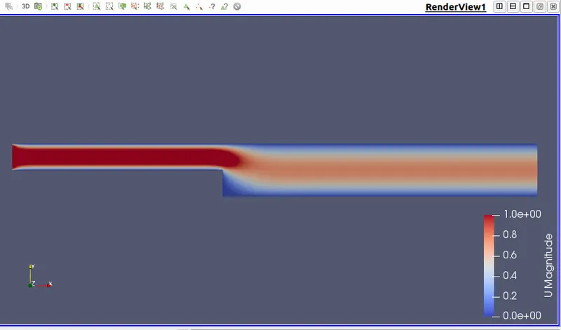
The inlet velocity is set to 1m/s and the outlet velocity is set as zero gradient. The front and back walls are given empty as the boundary condition because flow is not solved there. The top and bottom walls are given no slip boundary condition.
Initial setting for pressure
/*--------------------------------*- C++ -*----------------------------------*\
  =========                 |
  \\      /  F ield         | OpenFOAM: The Open Source CFD Toolbox
   \\    /   O peration     | Website:  https://openfoam.org
    \\  /    A nd           | Version:  9
     \\/     M anipulation  |
\*---------------------------------------------------------------------------*/
FoamFile
{
    format      ascii;
    class       volScalarField;
    object      p;
}
// * * * * * * * * * * * * * * * * * * * * * * * * * * * * * * * * * * * * * //

dimensions      [0 2 -2 0 0 0 0];

internalField   uniform 0;

boundaryField
{
    inlet
    {
        type            zeroGradient;
    }

    outlet
    {
        type            fixedValue;
        value           uniform 0;
    }

    fixedWalls
    {
        type            zeroGradient;
    }

    frontAndBack
    {
        type            empty;
    }
}

// ************************************************************************* //
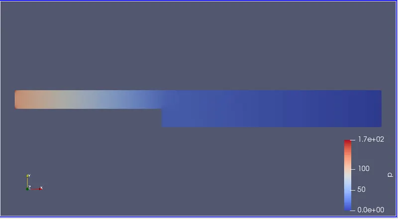
The inlet pressure is set to zero gradient. The pressure is assumed constant here.
The front and the back walls are given the condition empty. For top and bottom walls zero gradient is given.
Results
Mesh
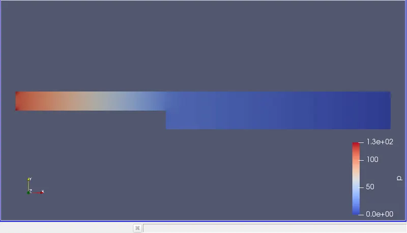
Pressure distribution
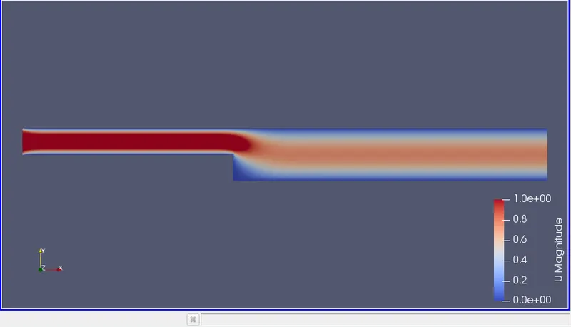
Velocity distribution
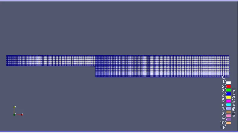
Case 2 - Simulate the flow with grading factor of 0.2. The cells should be finer near the walls (includig the step wall)
The blockMeshDict script file has to be changed since the grading factor is changed. All other files are the same.
blockMeshDict
/*--------------------------------*- C++ -*----------------------------------*\
  =========                 |
  \\      /  F ield         | OpenFOAM: The Open Source CFD Toolbox
   \\    /   O peration     | Website:  https://openfoam.org
    \\  /    A nd           | Version:  9
     \\/     M anipulation  |
\*---------------------------------------------------------------------------*/
FoamFile
{
    format      ascii;
    class       dictionary;
    object      blockMeshDict;
}
// * * * * * * * * * * * * * * * * * * * * * * * * * * * * * * * * * * * * * //

convertToMeters 0.01;

vertices
(
    (0 0 0) //0
    (8 0 0) //1
    (8 0.5 0) //2
    (0 0.5 0) //3
    (8 1 0) //4
    (0 1 0) //5
    (20 1 0)//6
    (20 0.5 0) //7
    (20 0 0) //8
    (20 -1 0) //9
    (8 -1 0) //10
    (0 0 0.1) //11
    (8 0 0.1) //12
    (8 0.5 0.1) //13
    (0 0.5 0.1) //14
    (8 1 0.1) //15
    (0 1 0.1) //16
    (20 1 0.1) //17
    (20 0.5 0.1) //18
    (20 0 0.1) //19
    (20 -1 0.1) //20
    (8 -1 0.1) //21
);

blocks
(
    hex (0 1 2 3 11 12 13 14) (80 5 1) simpleGrading (5 5 1)
    hex (3 2 4 5 14 13 15 16) (80 5 1) simpleGrading (5 0.2 1)
    hex (2 7 6 4 13 18 17 15) (120 5 1) simpleGrading (5 0.2 1)
    hex (1 8 7 2 12 19 18 13) (120 5 1) simpleGrading (5 5 1)
    hex (10 9 8 1 21 20 19 12) (120 10 1) simpleGrading (5 5 1)
);

edges
(
);

boundary
(
    inlet
    {
        type patch;
        faces
        (
            (0 11 14 3)
            (3 14 16 5)
        );
    }
    outlet
    {
        type patch;
        faces
        (
            (9 8 19 20)
            (8 7 18 19)
            (7 6 17 18)
        );
    }
    fixedWalls
    {
        type wall;
        faces
        (
            (6 4 15 17)
            (4 5 16 15)
            (10 21 12 1)
            (12 11 0 1)
            (20 21 10 9)
        );
    }
    frontAndBack
    {
        type empty;
        faces
        (
            (14 13 15 16)
            (11 12 13 14)
            (21 20 19 12)
            (12 19 18 13)
            (13 18 17 15)
            (5 4 2 3)
            (0 3 2 1)
            (1 8 9 10)
            (2 7 8 1)
            (4 6 7 2)
        );
    }
);

mergePatchPairs
(
);

// ************************************************************************* //
Results
Mesh
Pressure distribution
Velocity distribution
Comparing the velocity plots for both case studies
Case 1 (grading factor = 1)
Velocity profile at 0.085 m from the inlet
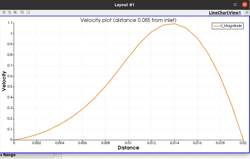
Case 2 (grading factor = 0.2)
Velocity profile at 0.085 m from the inlet
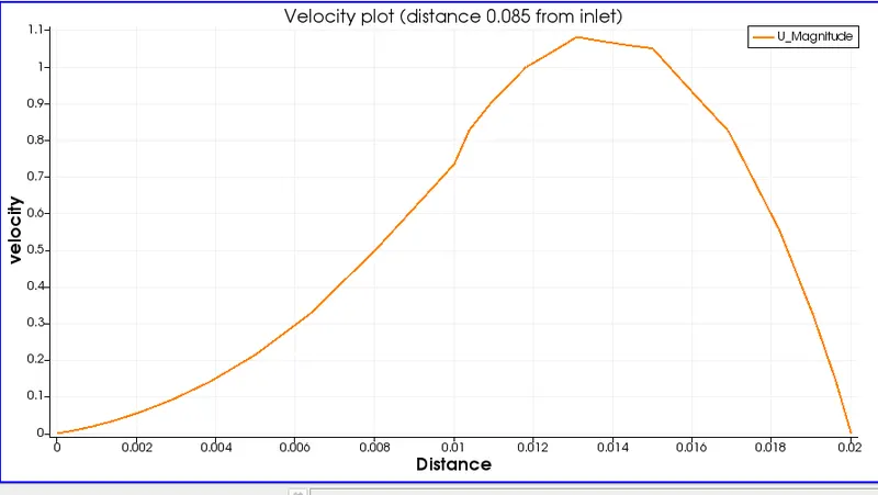
By comparing the velocity plots of both cases we can see that for case 1, where the grading factor is 1, produces a smooth curve because the cells are uniform.
While for case 2, where the grading factor is 0.2, the curve is finer with edges.
It took more time to solve case 2 than case 1, this is beacuse the mesh is more finer in case 2.
The velocity plot for grading factor 0.2 gives more accurate solution.
Why Grading/Growth factor is essential for meshing?
The grading factor in blockMesh is defined as the ratio of the last to first cell size. We can set the grading factor for each block as per our need. By giving more finer mesh we get more accurate results. As the mesh is more finer the computational time required will be also more.