Simulating Cyclone separator with Discrete Phase Modelling
AIM: To perform analysis on cyclone separator and calculate the separation efficiency and pressure drop.
OBJECTIVES:
- To write a few words about any four empirical models used to calculate the cyclone separator efficiency.
- To perform an analysis on a given cyclone separator model by varying the particle diameter from 1 μm to 5 μm and calculate the separation efficiency in each case. Discuss the results. (Use both the velocity's as 3m/sec.)
- To perform an analysis on a given cyclone separator model by varying the particle velocity from 1 m/sec to 5 m/sec and calculate the separation efficiency and pressure drop in each case. Discuss the results. (Use particle diameter size as 5 μm for all cases & keep flow velocity same as particle velocity).
THEORY:
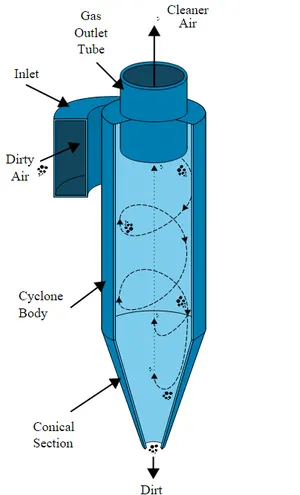
Cyclone Separator: Cyclone separators are separation devices that use the principle of inertia to remove particulate matter from flue gases. It consists of an upper cylindrical part referred to as the barrel and a lower conical part referred to as cone. They simply transform the inertia force of gas particle flows to a centrifugal force by means of a vortex generated in the cyclone body. The particle laden air stream enters tangentially at the top of the barrel and travels downward into the cone forming an outer vortex. The increasing air velocity in the outer vortex results in a centrifugal force on the particles separating them from the air stream. When the air reaches the bottom of the cone, it begins to flow radially inwards and out the top as clean air/gas while the particulates fall into the dust collection chamber attached to the bottom of the cyclone.
Some empirical models used to calculate the cyclone separator efficiency.
Iozia and Leith Model: This logistic model is a modified version of Barth model, which is developed based on force balance. The model assumes that a particle carried by the vortex endures the influence of two forces; centrifugal force and flow resistance.
Lapple model: This model is developed based on force balance without considering flow resistance. Lapple assumed that a particle that a entering the cyclone is evenly distributed across the inlet opening and a particle that travels from the inlet half width to the cyclone wall is collected with 50% efficiency.
Li and Wang model: This model obtains a two-dimensional analytical equation for cyclone separator efficiency by including turbulent diffusion and bounce or re-entrainment of the particles at the walls of the cyclone separator. It is based on the following assumptions:
- The radial particle velocity and the radial concentration profile are not constant for uncollected particles within the cyclone.
- Boundary conditions at the wall are defined considering turbulent diffusion and bounce or re-entrainment.
- The tangential velocity is related to the radius of cyclone
Koch and Licht model: This model recognizes the turbulent nature of cyclones and the distribution of gas residence time within the cyclone. It is based on the following assumptions;
- There is no slip in the tangential direction between the particle and the gas.
- The tangential velocity is related to the radius of cyclone.
PROCEDURE:
Geometry: The cyclone separator STEP file was imported to SpaceClaim and volume was extracted by selecting the edges using the volume extract tool.
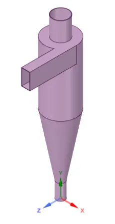
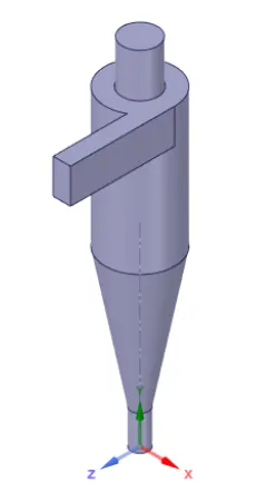
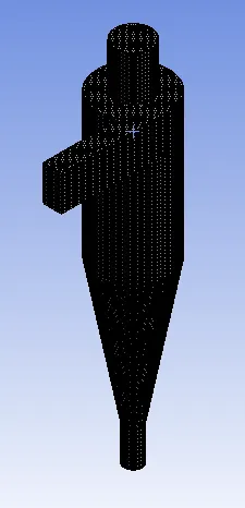
Mesh: The cyclone separator model was meshed with the following configuration:
Element size = 4 mm
Maximum size = 4 mm
Total number of nodes = 456576
Total number of elements = 427841
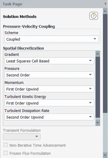
Setup and Solution:
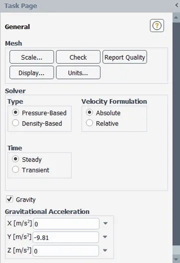
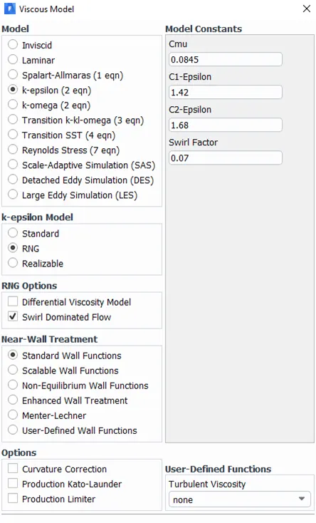
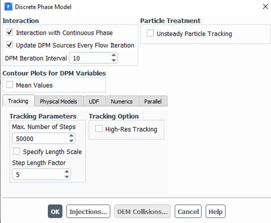
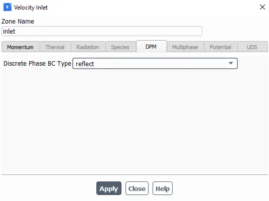
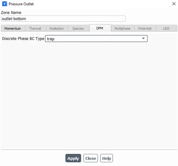
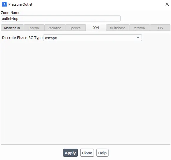
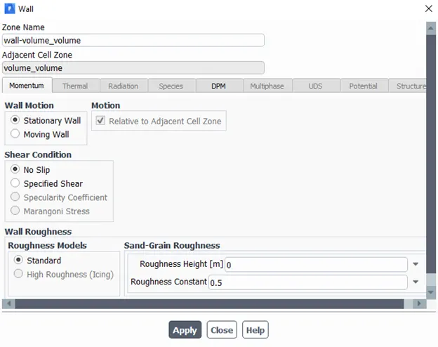
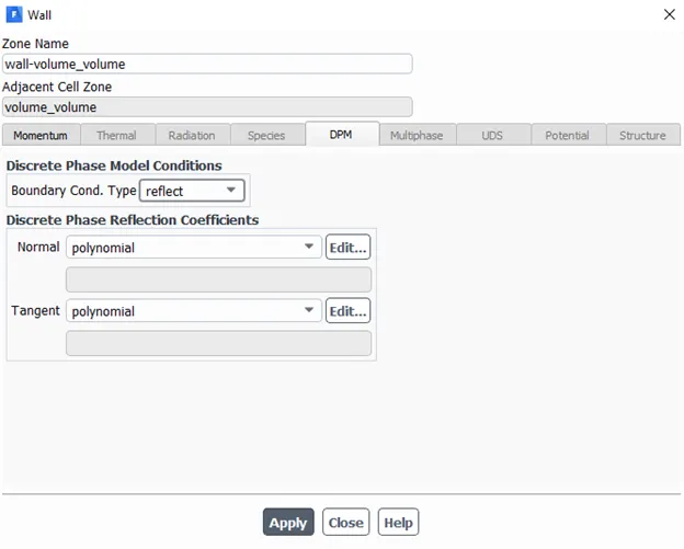
|
Case |
Inlet velocity (m/s) |
Particle diameter (m) |
|
Case 1 |
3 |
1e-6 |
|
Case 2 |
3e-6 |
|
|
Case 3 |
5e-6 |
|
|
Case 4 |
1 |
5e-6 |
|
Case 5 |
3 |
|
|
Case 6 |
5 |
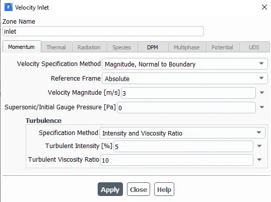
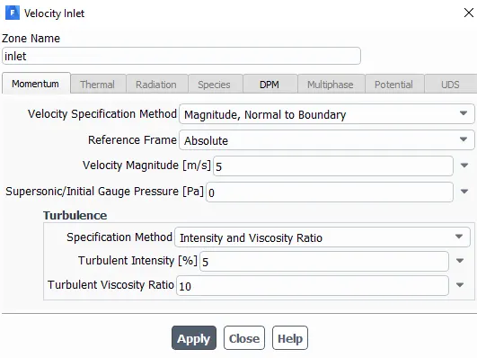
NOTE: Since we are simulating a coupled flow, the inlet velocity and particle velocity will be the same.
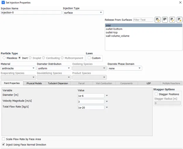
Case 1:
Diameter = 1e-6 m
Velocity = 3 m/s
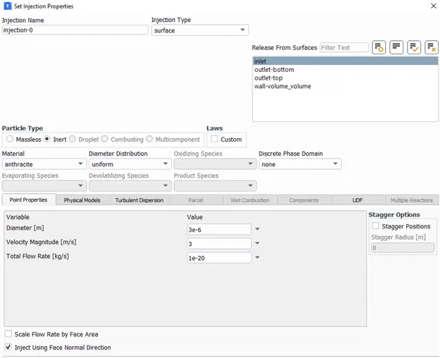
Case 2:
Diameter = 3e-6 m
Velocity = 3 m/s
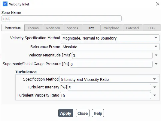
Case 3:
Diameter = 5e-6 m
Velocity = 3 m/s

Case 4:
Diameter = 5e-6 m
Velocity = 1 m/s
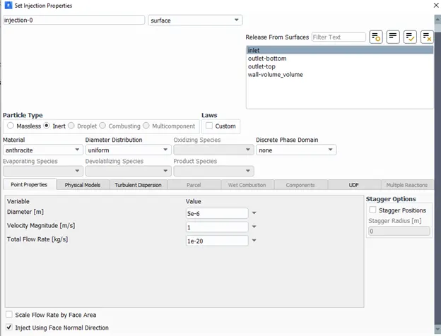
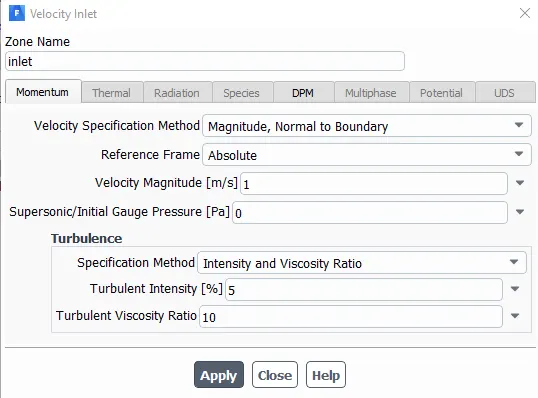
Case 5:
Diameter = 5e-6 m
Velocity = 3 m/s
Case 6:
Diameter = 5e-6 m
Velocity = 5 m/s
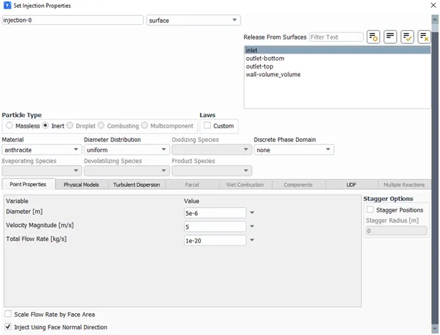
Results:
Case 1:
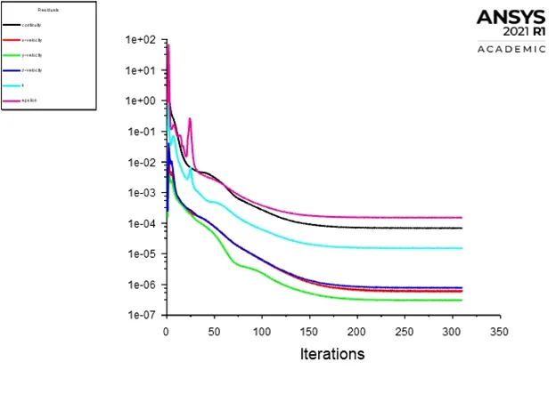
Residuals
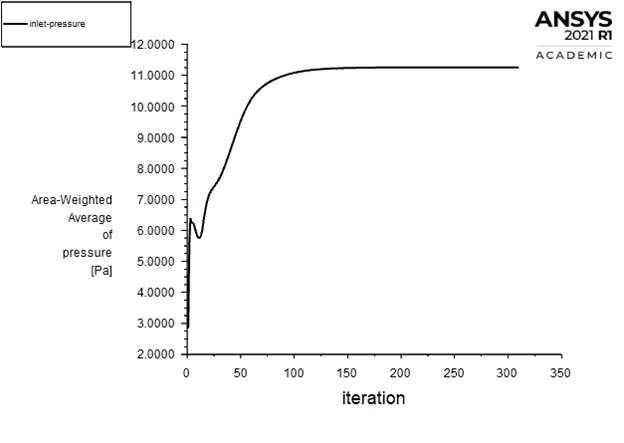
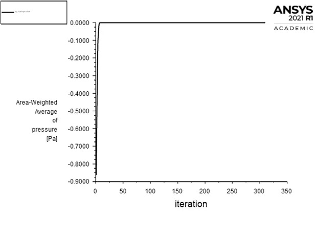
Inlet pressure
Bottom outlet pressure
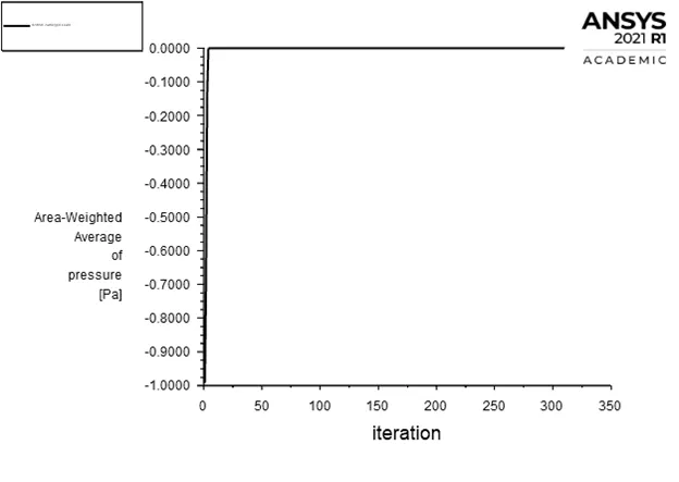
Top outlet pressure

Separation efficiency = number of particles trapped/number of particles tracked = 171/378 = 45.23 %
Link for animation: click here
Case 2:
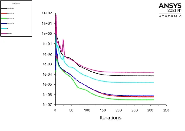
Residuals
Inlet pressure
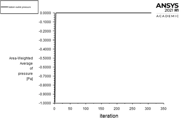
Bottom outlet pressure
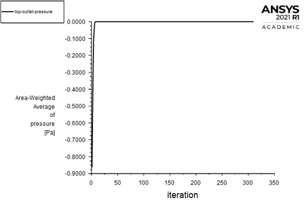
Top outlet pressure

Separation efficiency = number of particles trapped/number of particles tracked = 192/378 = 50.79 %
Link for animation: click here
Case 3:
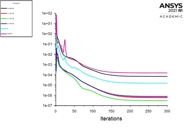
Residuals
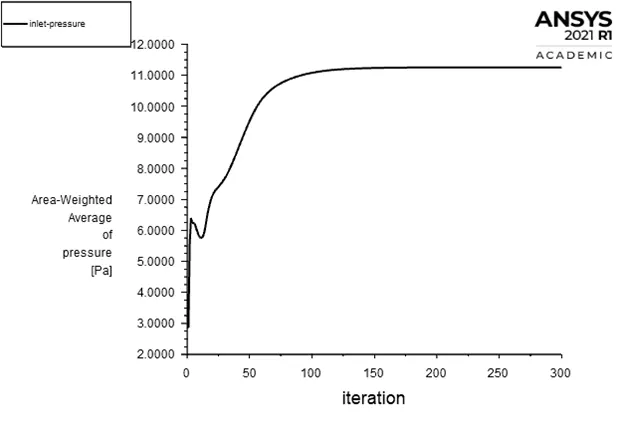
Inlet pressure
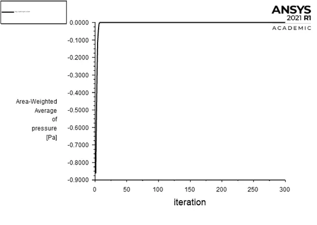
Bottom outlet pressure
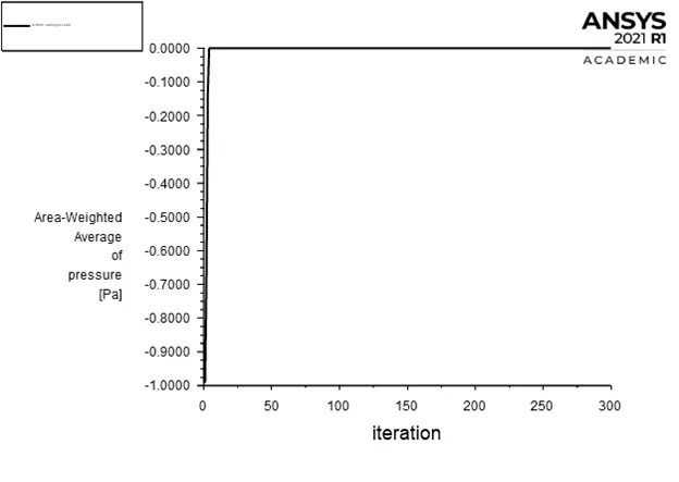
Top outlet pressure

Separation efficiency = number of particles trapped/number of particles tracked = 232/378 = 61.37 %
Link for animation: click here
Case 4:
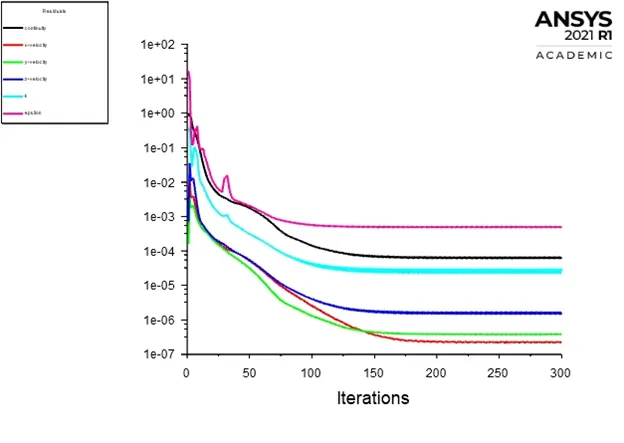
Residuals
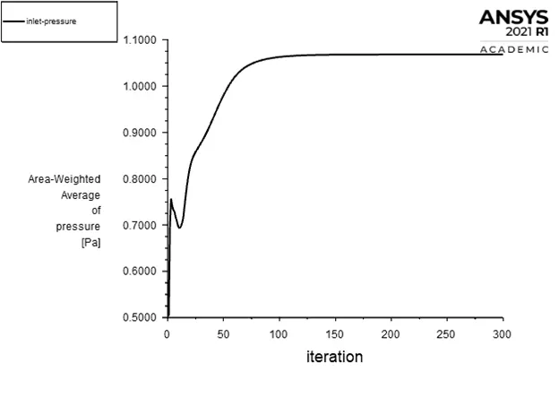
Inlet pressure
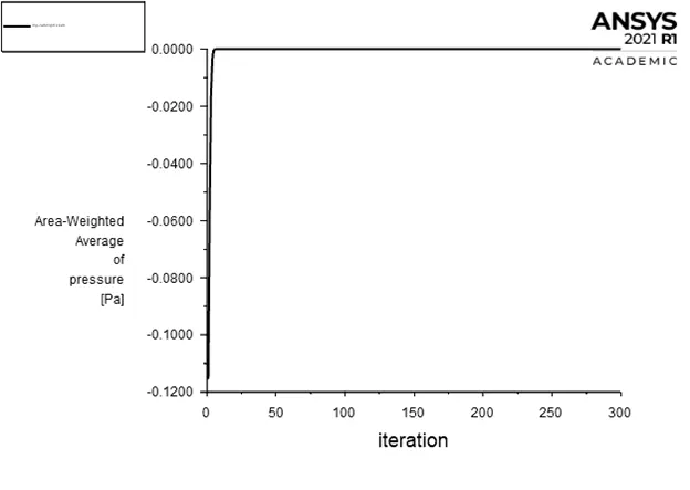
Bottom outlet pressure
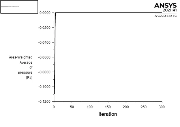
Top outlet pressure

Separation efficiency = number of particles trapped/number of particles tracked = 118/378 = 31.21 %
Link for animation: click here
Case 5:
Residuals
Inlet pressure
Bottom outlet pressure
Top outlet pressure
Separation efficiency = number of particles trapped/number of particles tracked = 232/378 = 61.37 %
Link for animation: click here
Case 6:
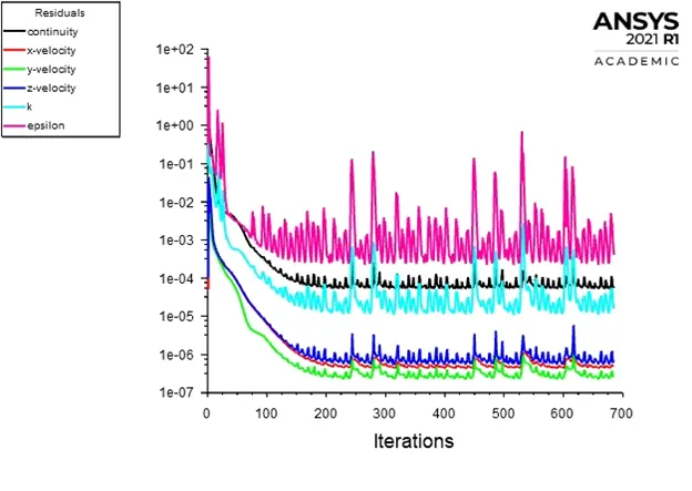
Residuals
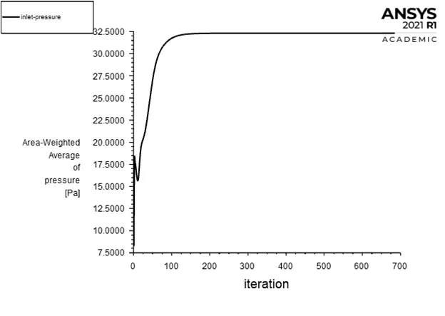
Inlet pressure
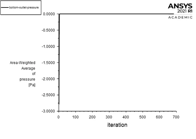
Bottom outlet pressure
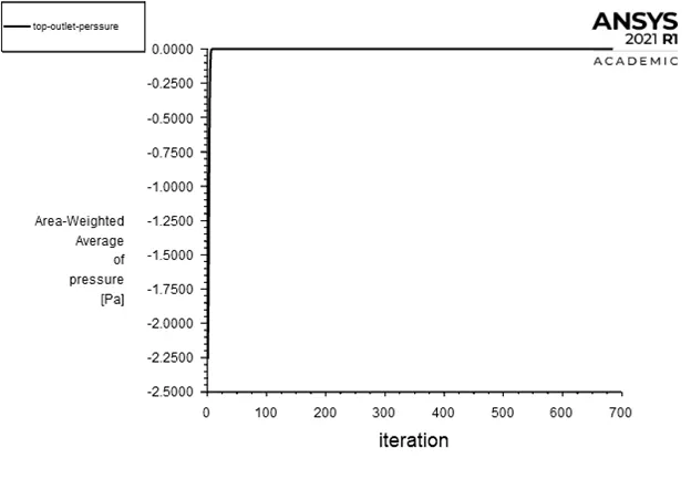
Top outlet pressure

Separation efficiency = number of particles trapped/number of particles tracked = 256/378 = 67.72 %
Link for animation: click here
OBSERVATIONS:
Separation efficiency:
|
Inlet/Particle velocity (m/s) |
Diameter (m) |
Tracked |
Escaped |
Trapped |
Incomplete |
Efficiency (%) |
|
|
Case 1 |
3 |
1e-6 |
378 |
191 |
171 |
16 |
45.23 |
|
Case 2 |
3e-6 |
378 |
172 |
192 |
14 |
50.79 |
|
|
Case 3 |
5e-6 |
378 |
124 |
232 |
22 |
61.37 |
|
|
Case 4 |
1 |
5e-6 |
378 |
118 |
195 |
65 |
31.21 |
|
Case 5 |
3 |
378 |
124 |
232 |
22 |
61.37 |
|
|
Case 6 |
5 |
378 |
74 |
256 |
48 |
67.72 |
Pressure drop:
|
Inlet/Particle velocity (m/s) |
Diameter (m) |
Inlet pressure (Pa) |
Top outlet pressure (Pa) |
Bottom outlet pressure (Pa) |
Pressure drop (Pa) |
|
|
Case 1 |
3 |
1e-6 |
11.25 |
0 |
0 |
11.25 |
|
Case 2 |
3e-6 |
11.25 |
0 |
0 |
11.25 |
|
|
Case 3 |
5e-6 |
11.25 |
0 |
0 |
11.25 |
|
|
Case 4 |
1 |
5e-6 |
1.06 |
0 |
0 |
1.06 |
|
Case 5 |
3 |
11.25 |
0 |
0 |
11.25 |
|
|
Case 6 |
5 |
32.31 |
0 |
0 |
32.31 |
CONCLUSION:
- Separation efficiency increases with increase in particle diameter for the same particle velocity as seen in the first three cases.
- Separation efficiency increases with increase in particle velocity for the same particle diameter as seen in the last three cases.
- Varying the particle diameter for the same particle velocity has no effect on the pressure drop.
- Changing the particle velocity for the same particle diameter increased the pressure drop.
- Efficiency of a cyclone separator depends on both velocity and the particle diameter. Higher the velocity and particle diameter, higher is the separation efficiency.
- Higher the particle velocity, higher is the pressure drop, hence, higher is the separation efficiency.