CHT Analysis on a Graphics card
AIM: To simulate a steady-state conjugate heat transfer analysis on a graphics card.
INTRODUCTION:
Conjugate Heat Transfer: Conjugate heat transfer corresponds with the combination of heat transfer in solids and heat transfer in fluids. In solids, conduction often dominates whereas in fluids, convection usually dominates.
In solids, if heat transfer occurs due to conduction, it is described by Fourier’s law.
For fluid motion, the following contributions to the heat equation are included:
- The transport of fluid implies energy transport too, which appears in the heat equation as the convective contribution.
- The viscous effects of the fluid flow produce fluid heating. This term is often neglected, nevertheless, its contribution is noticeable for fast flow in viscous fluids.
- As soon as a fluid density is temperature-dependent, a pressure work term contributes to the heat equation.
Applications of conjugate heat analysis:
- Effective heat transfer
- Energy Conservation, etc.
PROCEDURE:
Geometry: The graphics card stp file was imported into SpaceClaim and share topology was enabled in order to have a conformal mesh.
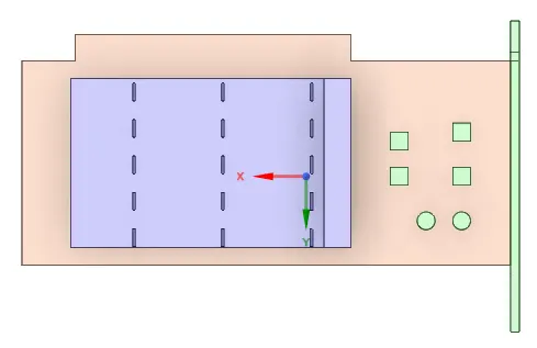
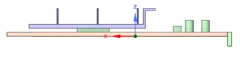
Mesh:
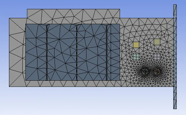
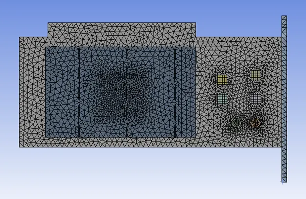
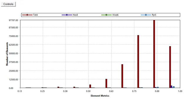
Baseline mesh:
Element size = 10.289 mm (Default)
Total number of elements = 83347


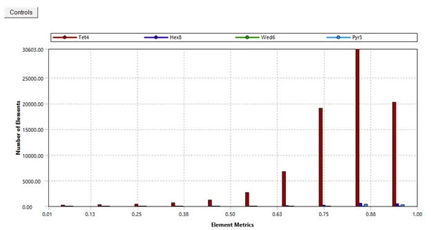
Refined mesh:
Fin body sizing = 1 mm
Processor body sizing = 0.3 mm
Base body sizing = 1 mm
Total number of elements = 291848


Setup and solution:
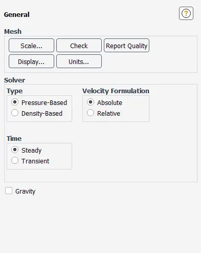
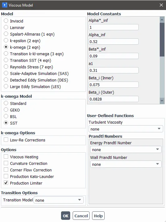
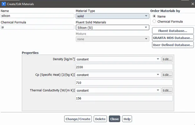
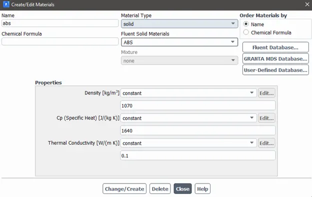
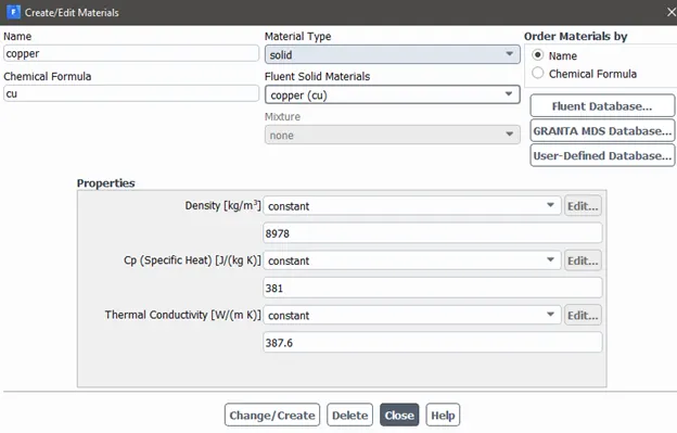
Following table shows the list of assigned materials to the components
|
Component |
Material |
|
Processor |
Silicon (Si) |
|
Graphic card base |
ABS |
|
Fins |
Copper (Cu) |
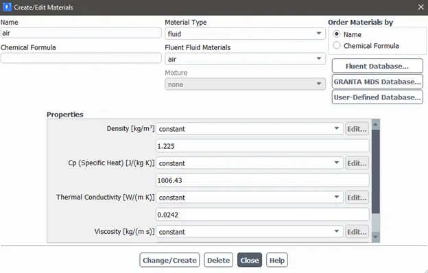
The fluid medium used will be air.
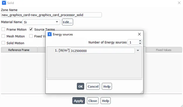
Let’s assume that the power consumed by the processor = 20 W
Volume of the processor = `8*8*1` mm3 = 64 mm3
Energy produced by the processor = 312500000 W/m3
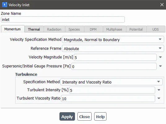
Baseline mesh:
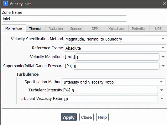
Case 1:
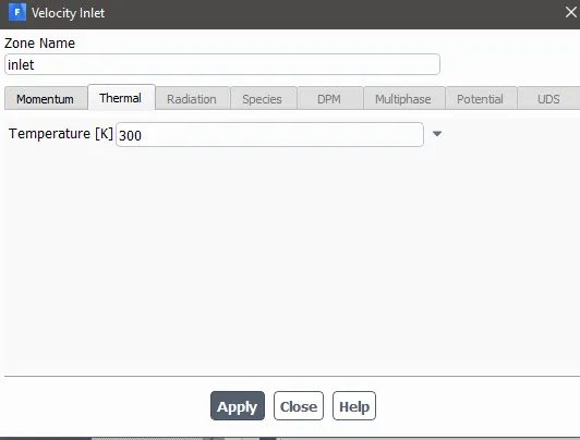
Case 2:
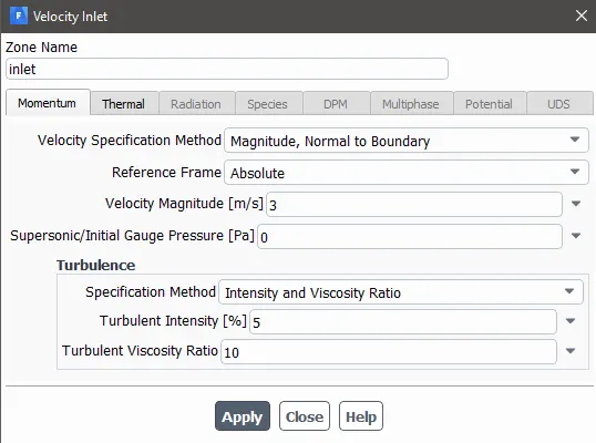
Case 3:
Refined mesh:
Case 1:
Case 2:
Case 3:
Results:
Baseline Mesh:
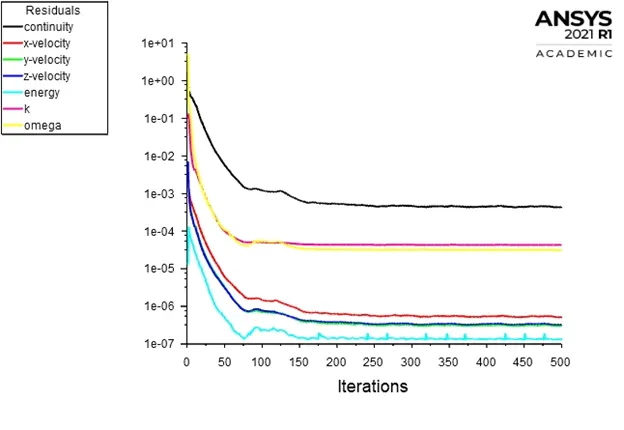
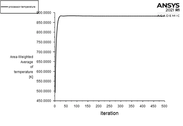
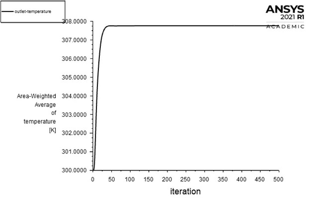
Case 1:
Residuals
Processor Temperature
Outlet temperature
Temperature contour
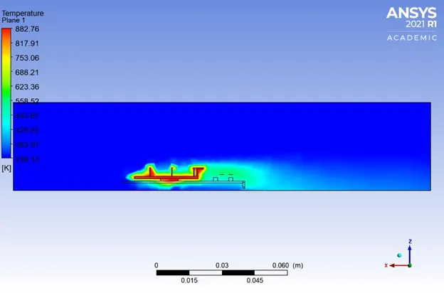
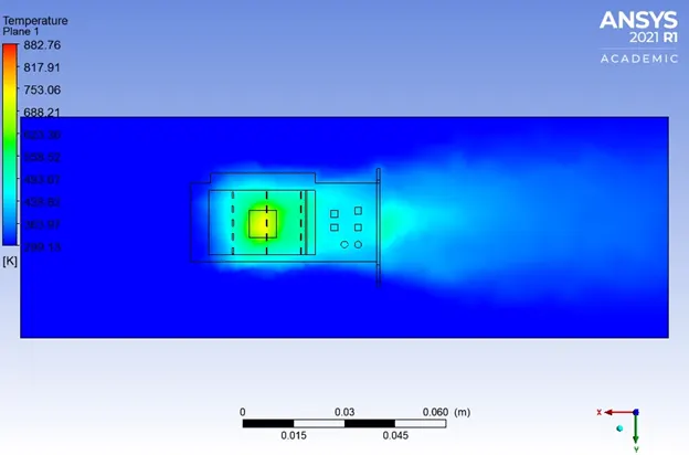
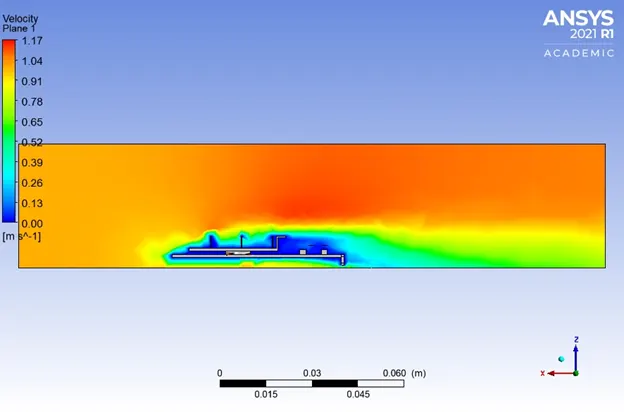
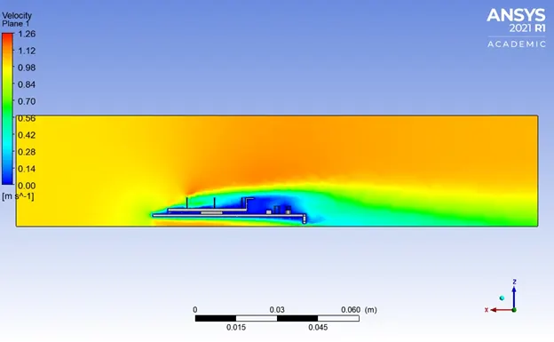
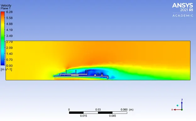
Velocity contour
Case 2:
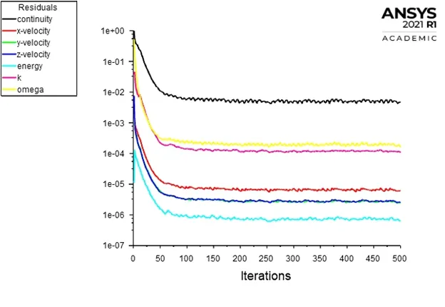
Residuals
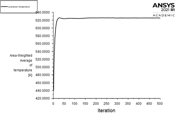
Processor Temperature
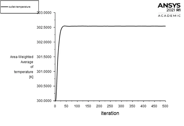
Outlet temperature
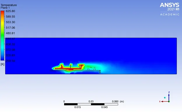
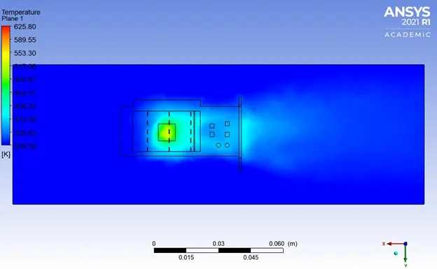
Temperature contour
Velocity contour
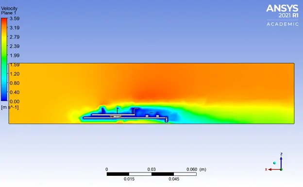
Case 3:
Residuals
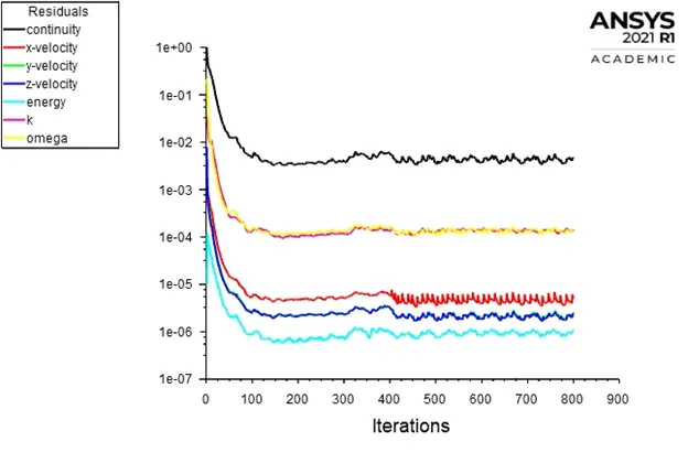
Processor Temperature
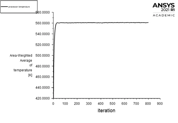
Outlet temperature
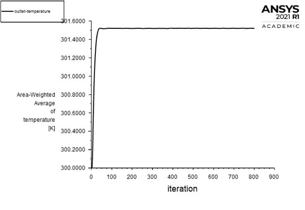
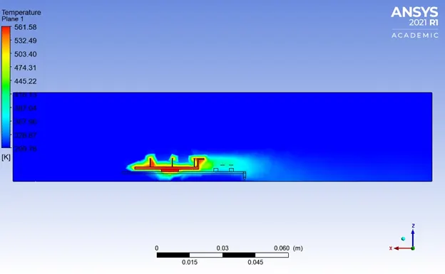
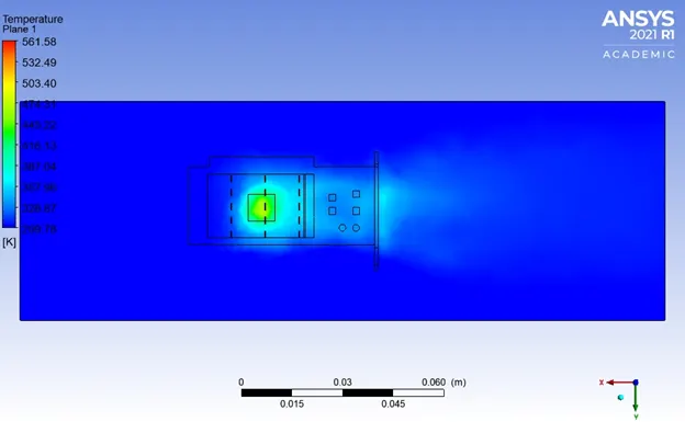
Temperature contour
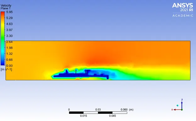
Velocity contour
Refined Mesh
Case 1:
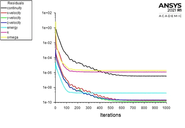
Residuals
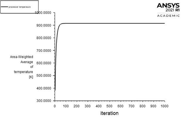
Processor Temperature
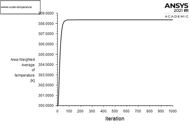
Outlet temperature
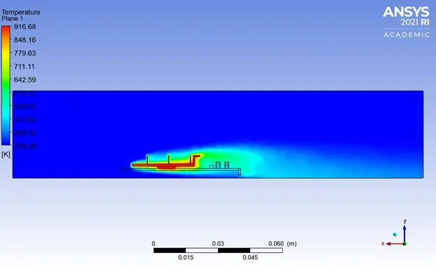
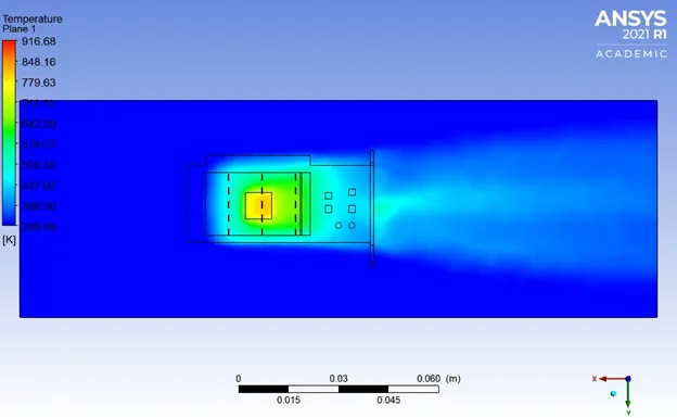
Temperature contour
Velocity contour
Case 2:
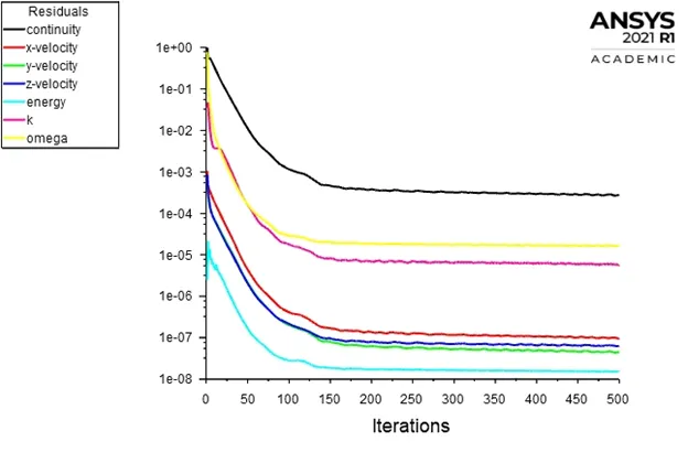
Residuals
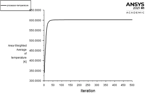
Processor Temperature
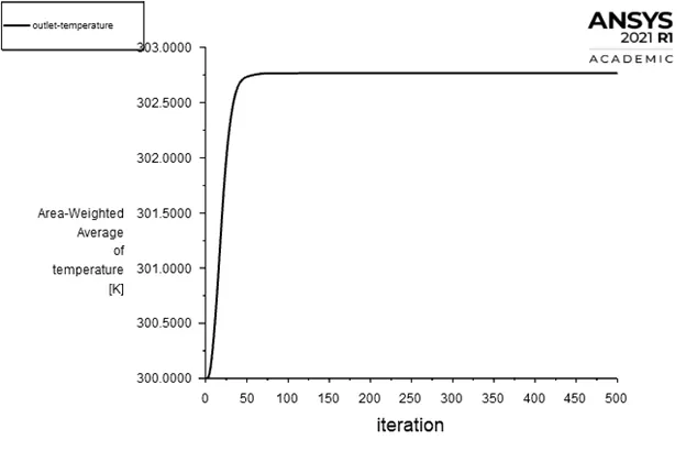
Outlet temperature
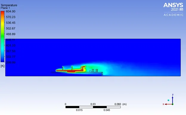
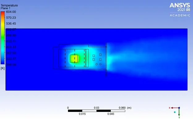
Temperature contour
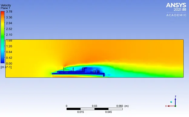
Velocity contour
Case 3:
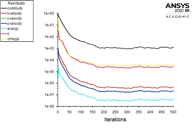
Residuals
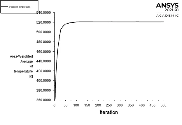
Processor Temperature
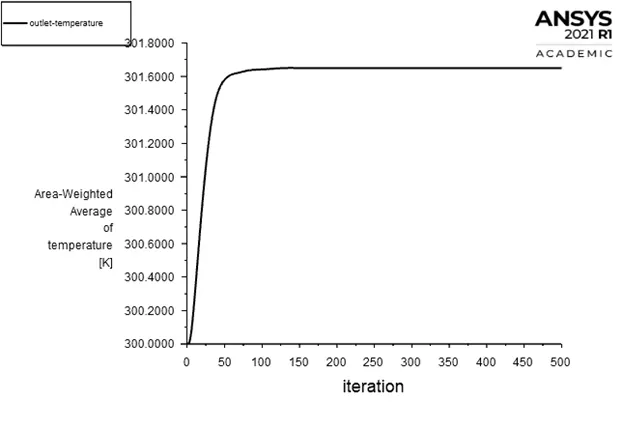
Outlet temperature
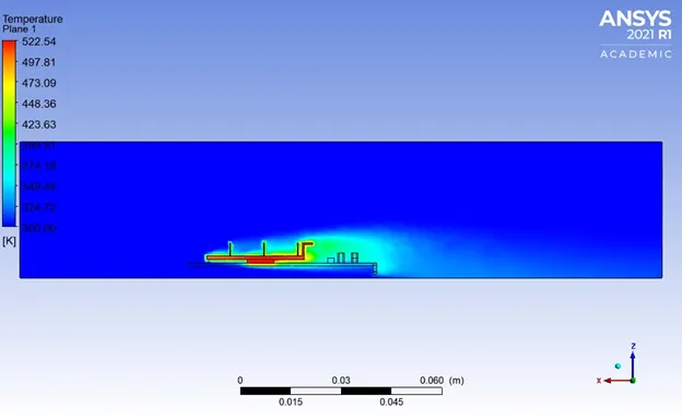
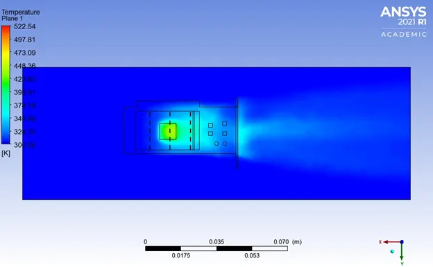
Temperature contour
Velocity contour
Observations:
|
Mesh |
Inlet Velocity (m/s) |
Outlet Temperature (K) |
Processor Temperature (K) |
Surface HTC (W/m2K) |
|
Baseline Mesh |
1 |
307.7 |
882.2 |
210.5 |
|
3 |
302.5 |
625.3 |
384.8 |
|
|
5 |
301.5 |
560.8 |
480.5 |
|
|
Refined Mesh |
1 |
308.3 |
914.7 |
203.5 |
|
3 |
302.7 |
602.1 |
414.4 |
|
|
5 |
301.6 |
520.7 |
567.7 |
Conclusion:
- A refined mesh provides more accurate results than a coarse mesh.
- As the inlet air velocity increases, outlet temperature decreases.
- As the inlet air velocity increases, maximum temperature attained by processor decreases.
- As the inlet air velocity increases, surface heat transfer coefficient increases.
- Since Copper (Cu) is good conductor of heat and electricity, it is selected as the fin material as it helps to dissipate the heat faster and thus cool the processor.