Week 8 - Simulating Cyclone separator with Discrete Phase Modelling
To write a few words about any four empirical models used to calculate the cyclone separator efficiency.
Cyclone separators or simply cyclones are separation devices (dry scrubbers) that use the principle of inertia to remove particulate matter from flue gases Cyclone separators is one of many air pollution control devices known as precleaners since they generally remove larger pieces of particulate matter. This prevents finer filtration methods from having to deal with large, more abrasive particles later on. In addition, several cyclone separators can operate in parallel, and this system is known as a multicyclone.
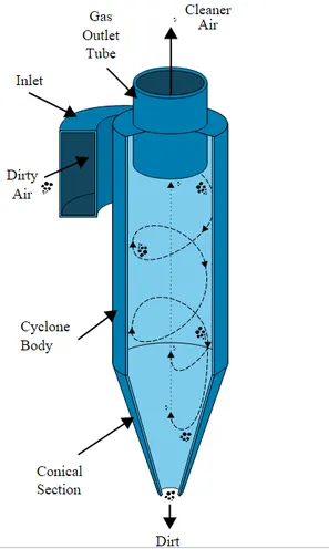
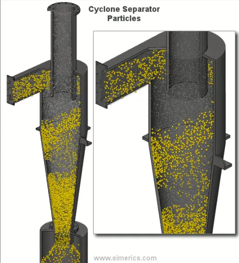
Cyclone separators work much like a centrifuge, but with a continuous feed of dirty air. In a cyclone separator, dirty flue gas is fed into a chamber. The inside of the chamber creates a spiral vortex, similar to a tornado. This spiral formation and the separation is shown in Figure
CYCLONE EFFICIENCY EMPIRICAL MODELS:
1.Iozia and Leith Model: It is developed based on force balance.The model assumes that a particle carried by the vortex endures the influence of two forces: a centrifugal force, Z and a flow resistance, W. The collection efficiency ηi of particle diameter dpi can be calculated from
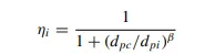
β is an expression for slope parameter derived based on the statistical analysis of experimental data of a cyclone with D =0.25 m given as

where core length, zc, and core diameter, dc, are given as
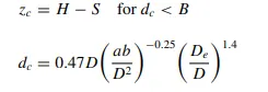
2.Li and Wang Model: The Li and Wang model includes particle bounce or reentrainment and turbulent diffusion at the cyclone wall. A twodimensional analytical expression of particle distribution in the cyclone is obtained. Li and Wang model was developed based on the following assumptions:
a) The radial particle velocity and the radial concentrationprofile are not constant for uncollected particles within the cyclone.
b) Boundary conditions with the consideration of turbu185 lent diffusion coefficient and particle bounce reentrainment on the cyclone wall are:
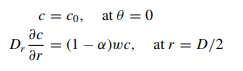
c) The tangential velocity is related to the radius of cyclone by: u Rn = constant.
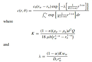
3.Koch and Licht Model:Koch and Licht collection theory recognized the inherently turbulent nature of cyclones and the distribution of gas residence times within the cyclone. Koch and Licht described particle motion in the entry and collection regions with the additional following assumptions:
• The tangential velocity of a particle is equal to the tangential velocity of the gas flow, i.e. there is no slip in the tangential direction between the particle and the gas.
• The tangential velocity is related to the radius of cyclone by: u Rn = constant.
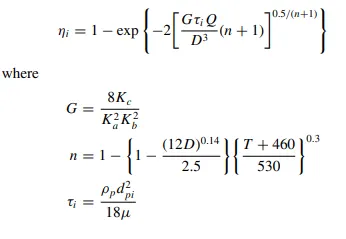
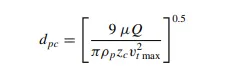
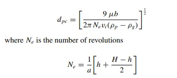
4. Lapple Model: Lapple model was developed based on force balance without considering the flow resistance. Lapple assumed that a par215 ticle entering the cyclone is evenly distributed across the inlet opening. The particle that travels from inlet half width to the wall in the cyclone is collected with 50% efficiency. The semiempirical relationship developed by Lapple to calculate a 50% cut diameter, dpc, is
1. To perform an analysis on a given cyclone separator model by varying the particle diameter from 1 μm to 5 μm and calculate the separation efficiency in each case. Discuss the results. [Use both the velocity's as 3m/sec.]
2. To perform an analysis on a given cyclone separator model by varying the particle velocity from 1 m/sec to 5 m/sec and calculate the separation efficiency and pressure drop in each case. Discuss the results. [Use particle diameter size as 5 μm for all cases & keep flow velocity same as particle velocity]
For doing this cyclone seperator analysis on ANSYS platform following steps have to be done on the software.
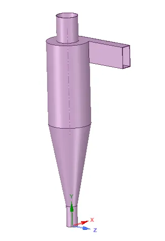
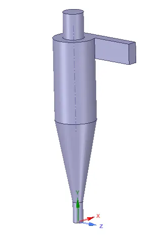
1. Spaceclaim: The cyclone seperator geometry is imported in the spaceclaim and the fluid zone is extracted. The extracted zone and the geometry can be seen below.
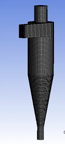
2. Meshing: The cut shell meshing approach is taken into account and the global size was taken to be of 7mm and the inlet face size is taken as 5mm. Then the inlet along with the two oulets is given the named selection.
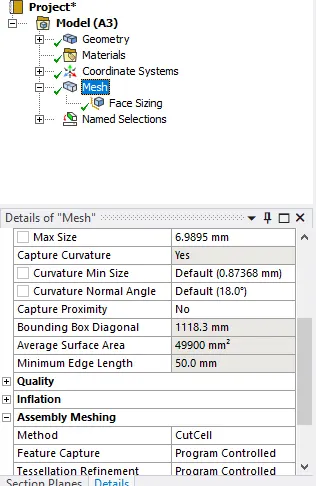
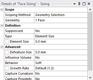
The meshing on the body can be observed as
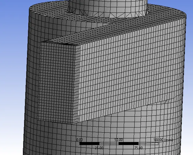
As the number of DPM particles depend upon the meshing so the face meshing is done at 5mm.
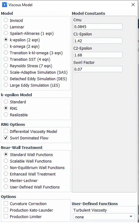
3. Setup: Gravity is enabled initially. Also K-epsilon model with standard wall funcion is enabled.
The DPM model is enabled with the following values:
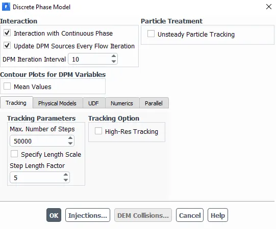
The injection is defined as the following (here for instance anthracite particle with 5m/s and 5micrometer diameter is injected).
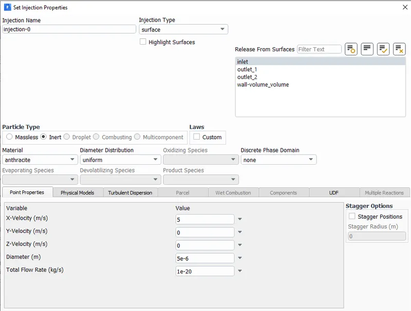
The Other boundries are mentioned with the required inlet velocity.
Inlet and wall:- Reflect
Outlet(Top):- Escape
Outlet(Bottom/dustbin) - Trap
The whole simulation is ru for 6 cases viz. 3 cases for a fixed diameter of particle and variable velocity. And 3 cases for fixed velocity and variable diamter.
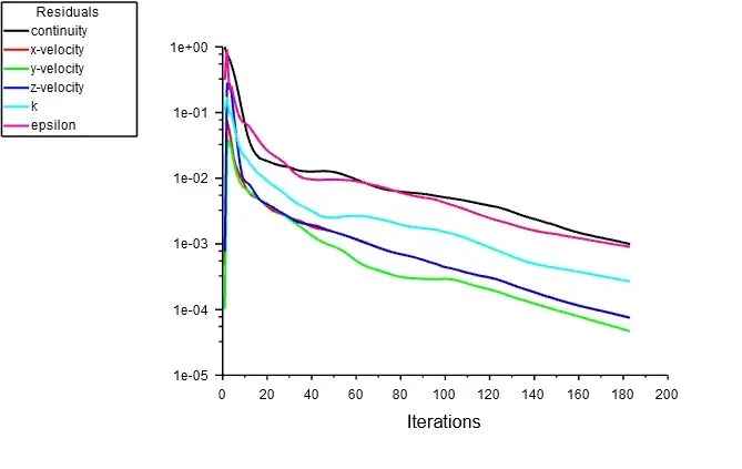
| Residuals | output | Efficiency(%) | time hstory plot | ||
|
Diameter = 1 um Inlet veloctiy = 3 m/s Particle velocity = 3 m/s |
 |
 |
39.31 | 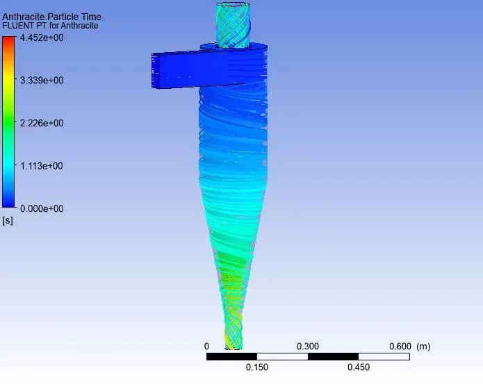 |
|
|
Diameter = 3 um Inlet veloctiy = 3 m/s Particle velocity = 3 m/s |
|
 |
69.1 | 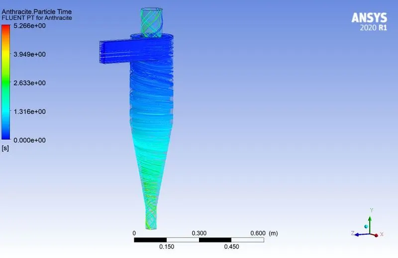 |
|
|
Diameter = 5 um Inlet veloctiy = 3 m/s Particle velocity = 3 m/s |
|
 |
97.0 | 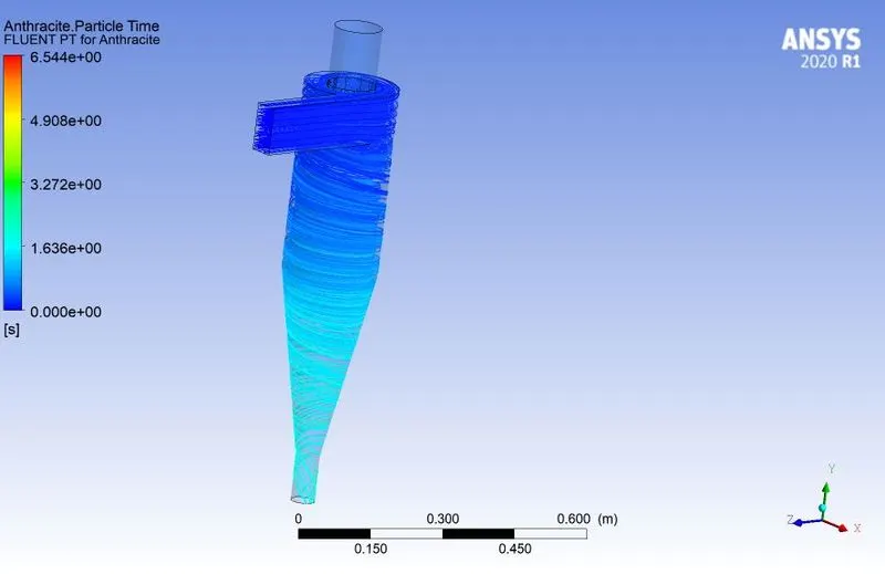 |
|
|
Diameter = 5 um Inlet veloctiy = 1 m/s Particle velocity = 1 m/s |
|
 |
6.436 | 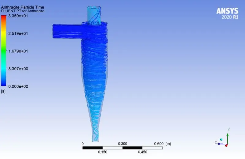 |
|
|
Diameter = 5 um Inlet veloctiy = 3 m/s Particle velocity = 3 m/s |
|
 |
97.0 | 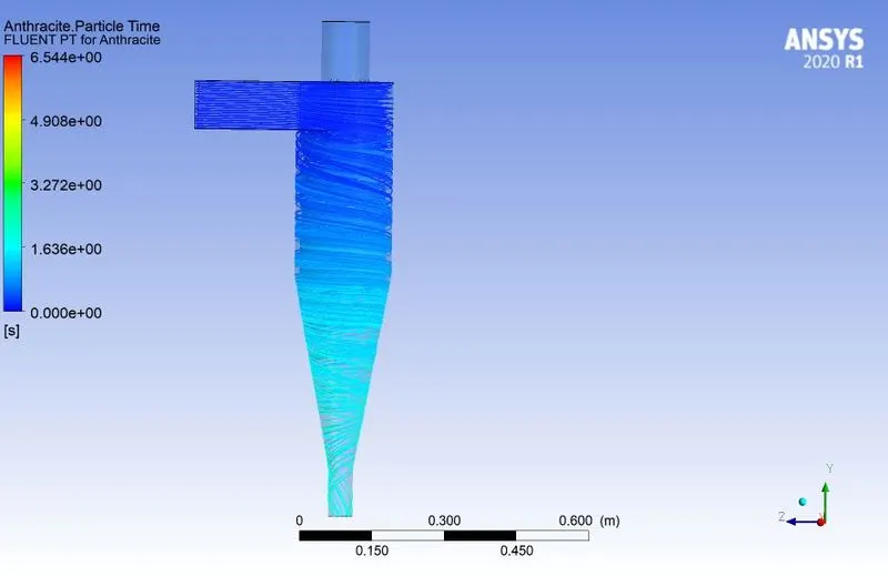 |
|
|
Diameter = 5 um Inlet veloctiy = 5 m/s Particle velocity = 5 m/s |
|
 |
97.47 | 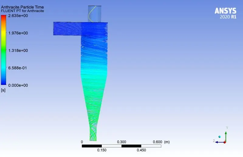 |
| Pressure plot | |
|
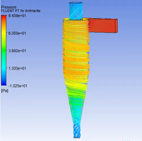
Diameter = 1 um Inlet veloctiy = 3 m/s Particle velocity = 3 m/s |
 |
|
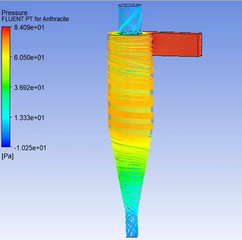
Diameter = 3 um Inlet veloctiy = 3 m/s Particle velocity = 3 m/s |
 |
|
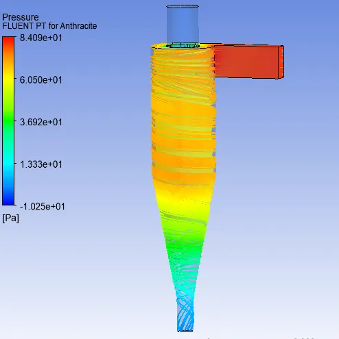
Diameter = 5 um Inlet veloctiy = 3 m/s Particle velocity = 3 m/s |
 |
|
Diameter = 5 um Inlet veloctiy = 1 m/s Particle velocity = 1 m/s |
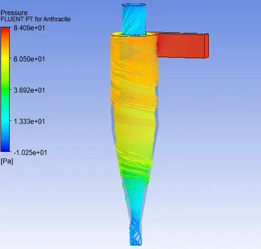 |
|
Diameter = 5 um Inlet veloctiy = 3 m/s Particle velocity = 3 m/s |
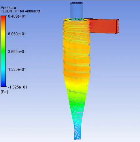 |
|
Diameter = 5 um Inlet veloctiy = 5 m/s Particle velocity = 5 m/s |
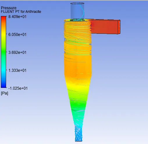 |
From the above table it can be concluded that:
1. As the diameter is increased by keeping the inlet velocity constant, the cyclone seperator efficiency increases.
2. When diameter is fixed and inlet velocity of the particle is increased then also the efficiency of the device increases.