Simulating Cyclone separator with Discrete Phase Modelling using ANSYS Fluent
Week8 Report
Aim: To perform an analysis on a given cyclone separator model by varying the particle diameter, particle velocity and calculate the separation efficiency.
Theoretical Introduction:
A cyclone separator is an economical device for removing particulate solids from a fluid system. The induced centrifugal force is tangentially imparted on the wall of the cyclone cylinder. This force, with the density difference between the fluid and solid, increases the relative Settling velocity.
Cyclone separators are extremely important for the successful operation of the cat cracker. Their performance impacts several FCC performance factors, including the additional cost of fresh catalyst makeup, extra turnaround maintenance costs, the allowable limits on the emission of particulates, and the incremental energy recovery in the WGC, and hot gas expander.
Designing an “optimum” set of cyclones requires a balance between the desired collection efficiency, pressure drop, space limitations, and installation cost.
Cyclonic separation is a method of removing particulates from an air, gas, or liquid stream, without the use of filters, through vortex separation. When removing particulate matter from liquid, a hydrocyclone is used; while from gas, a gas cyclone is used. Rotational effects and gravity are used to separate mixtures of solids and fluids. The method can also be used to separate fine droplets of liquid from a gaseous stream.
A high-speed rotating (air)flow is established within a cylindrical or Conical container called a cyclone. Air flows in a helical pattern, beginning at the top (wide end) of the cyclone and ending at the bottom (narrow) end before exiting the cyclone in a straight stream through the center of the cyclone and out the top. Larger (denser) particles in the rotating stream have too much inertia to follow the tight curve of the stream, and thus strike the outside wall, then fall to the bottom of the cyclone where they can be removed. In a conical system, as the rotating flow moves towards the narrow end of the cyclone, the rotational radius of the stream is reduced, thus separating smaller and smaller particles. The cyclone geometry, together with Volumetric flow rates, defines the cut point of the cyclone. This is the size of particle that will be removed from the stream with a 50% efficiency. Particles larger than the cut point will be removed with greater efficiency and smaller particles with a lower efficiency as they separate with more difficulty or can be subject to re-entrainment when the air vortex reverses direction to move in direction of the outlet.
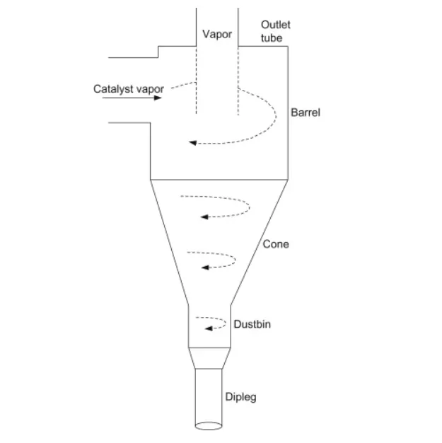
As the cyclone is essentially a two-phase particle-fluid system, fluid mechanics and particle transport equations can be used to describe the behavior of a cyclone. The air in a cyclone is initially introduced tangentially into the cyclone with an inlet velocity. Assuming that the particle is spherical, a simple analysis to calculate critical separation particle sizes can be established.
If one considers an isolated particle circling in the upper cylindrical component of the cyclone at a rotational radius of from the cyclone's central axis, the particle is therefore subjected to drag, Centrifugal, and buoyant forces. Given that the fluid velocity is moving in a spiral the gas velocity can be broken into two component velocities: a tangential component, and an outward radial velocity component. Assuming Stokes law, the drag force in the outward radial direction that is opposing the outward velocity on any particle in the inlet stream is:

Using  as the particle's density, the centrifugal component in the outward radial direction is:


The buoyant force component is in the inward radial direction. It is in the opposite direction to the particle's centrifugal force because it is on a volume of fluid that is missing compared to the surrounding fluid. Using  for the density of the fluid, the buoyant force is:


In this case,  is equal to the volume of the particle (as opposed to the velocity). Determining the outward radial motion of each particle is found by setting Newton's second law of motion equal to the sum of these forces:

To simplify this, we can assume the particle under consideration has reached "terminal velocity", i.e., that its acceleration is zero. This occurs when the radial velocity has caused enough drag force to counter the centrifugal and buoyancy forces. This simplification changes our equation to:

This expands to:
Solving for we have
 .
.
Notice that if the density of the fluid is greater than the density of the particle, the motion is (-), toward the center of rotation and if the particle is denser than the fluid, the motion is (+), away from the center. In most cases, this solution is used as guidance in designing a separator, while actual performance is evaluated and modified empirically.
In non-equilibrium conditions when radial acceleration is not zero, the general equation from above must be solved. Rearranging terms we obtain

Since  is distance per time, this is a 2nd order differential equation of the form
  .
.
Experimentally it is found that the velocity component of rotational flow is proportional to  , therefore:

This means that the established feed velocity controls the vortex rate inside the cyclone, and the velocity at an arbitrary radius is, therefore:

Subsequently, given a value for , possibly based upon the injection angle, and a cutoff radius, a characteristic particle filtering radius can be estimated, above which particles will be removed from the gas stream.
As an application of computational fluid dynamics (CFD) for the numerical calculation of the gas flow field becomes more and more popular. One of the first CFD simulations was done by Boysen. He found that the standard k–ε turbulence model is inadequate to simulate flows with swirl because it leads to excessive turbulence viscosities and unrealistic tangential velocities. Recent studies suggest that the Reynolds stress model (RSM) can improve the accuracy of the numerical solutions.
Currently, particle turbulent dispersion due to interaction between particles and turbulent eddies of fluid is generally dealt with by two methods: mean diffusion which characterizes only the overall mean (time-averaged) dispersion of particles caused by the mean statistical properties of the turbulence, and structural dispersion which includes the detail of the non-uniform particle concentration structures generated by local instantaneous features of the flow, primarily caused by the spatial-temporal turbulent eddies and their evolution. To predict the mean particle diffusion in turbulent flow, both Lagrangian and Eulerian techniques can be used. Since the early work of Yuu et al. and Gosman and Ioannides, the stochastic Lagrangian model has shown significant success in describing the turbulent diffusion of particles. It has been reported that it is necessary to trace up to 3 × 10⁵ particle trajectories in order to achieve a statistically meaningful solution even for a two-dimensional flow. In order to enhance such application in industries, some modified models were proposed. Sommerfeld and Simonin proposed Langevin stochastic differential equation models by making use of the possibility density function. Litchford and Jeng developed a stochastic dispersion-width transport model, where the dispersion-width is explicitly computed through the linearized equation of motion using the concept of particle–eddy interactions. Moreover, Chen and Pereira reported a SPEED model where a combined stochastic-probabilistic method is used to describe the turbulent motion of discrete particles so that only a small number of particle trajectories are required.
Source: https://www.sciencedirect.com/science/article/pii/S0307904X06000291
Four empirical models used to calculate the cyclone separator efficiency are given below:
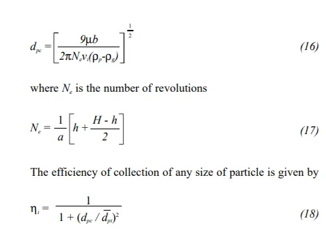
- Lapple model: Lapple (1951) model was developed based on force balance without considering the flow resistance. Apple assumed that a particle entering the cyclone is evenly distributed across the inlet opening. The particle that travels from the inlet half-width to the wall in the cyclone is collected with 50% efficiency. The semi-empirical relationship developed by Lapple (1951) to calculate a 50% cut diameter, DPC, is
- Li and Wang model:
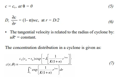
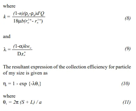
The Li and Wang (1989) model includes particle bounce orre-entrainment and turbulent diffusion at the cyclone wall. A two-dimensional analytical expression of particle distribution in the cyclone is obtained. Li and Wang model was developed
based on the following assumptions:
• The radial particle velocity and the radial concentration profile are not constant, for uncollected particles within the cyclones.
• Boundary conditions with the consideration of turbulent diffusion coefficient and particle bounce re-entrainment on
the cyclone wall are:
- Iozia and Leith: Iozia and Leith's (1990) logistic model is a modified version of Barth (1956) model which is developed based on force balance. The model assumes that a particle carried by the vortex endures the influence of two forces: a centrifugal force, Z, and flow resistance, W. Core length, zc, and core diameter, dc, are given as
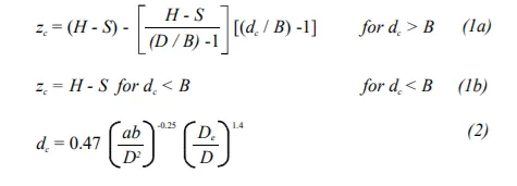 The addition made by Iozia and Leith on the original Barth (1956) model are the core length zc and slope parameter β expression which is derived based on the statistical analysis of experimental data of cyclone with D = 0.25 m. The collection
efficiency ηi of particle diameter dpi can be calculated from":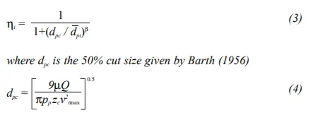
- Koch and Licht: Koch and Licht (1977) collection theory recognized the inherently turbulent nature of cyclones and the distribution of gas residence times within the cyclone. Koch and Licht describe particle motion in the entry and collection regions with the additional following assumptions:
• The tangential velocity of a particle is equal to the tangential velocity of the gas flow, i.e. there is no slip in the tangential direction between the particle and the gas.
• The tangential velocity is related to the radius of cyclone by:
uRn = constant.
A force balance and an equation on the particles collection yields the grade efficiency ηi
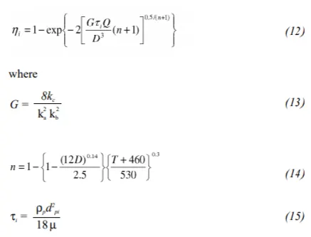 G is a factor related to the configuration of the cyclone, n is related to the vortex and τ is the relaxation term.
- Procedure:
Geometry and Modelling
Fluid extracted model
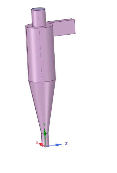
Inlet outlet 1
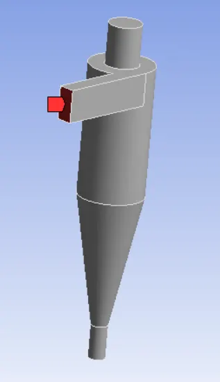
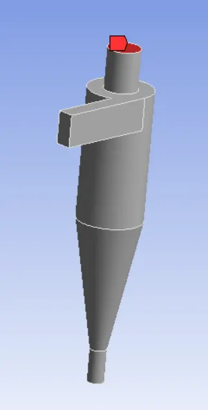
outlet 2
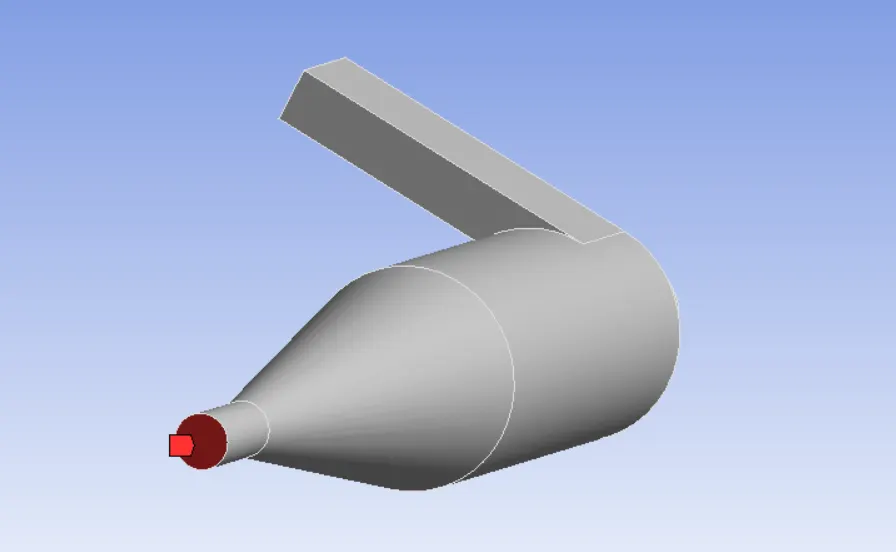
Preprocessing and Solver settings
meshing:
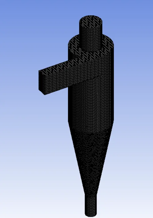
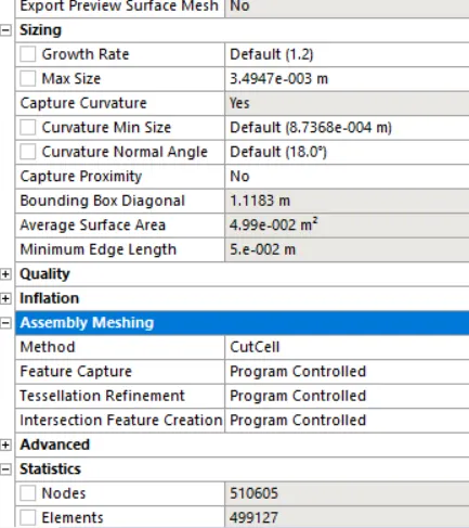
For meshing we have used Cut Cell Mesh as Structural mesh gives the best results, so we can use cutcell meshing approach available in Ansys Meshing. The size of elements is 3.5 *10^(-3)m. With close to 499127 elemnts.
Solver Setting:
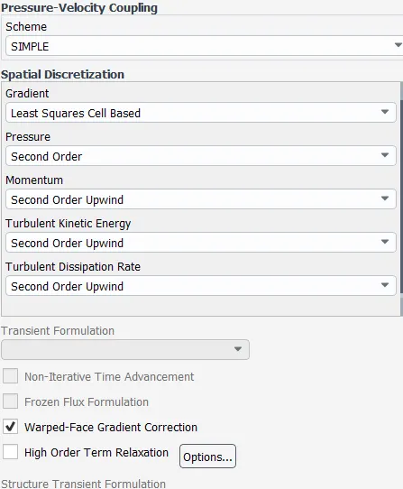
A Simple scheme with Turbulent Kinetic Energy and Turbulent Dissipation rate to be second Order upwind.
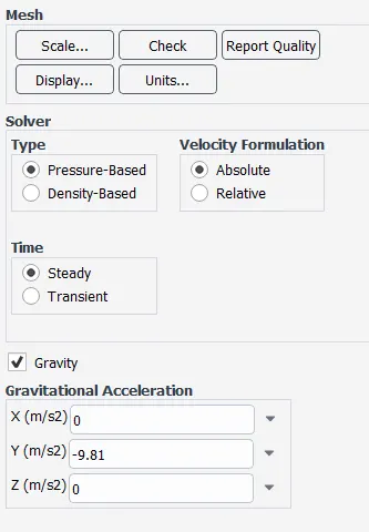
Gravity is turned on
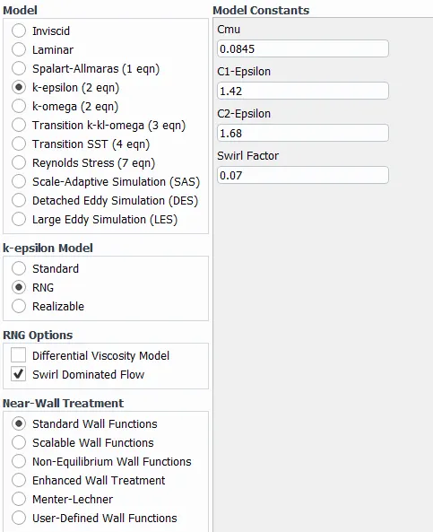
The turbulence model is K-epsilon RNG as it's good a capturing Swirl Flows.
Discrete Model Phase:(Coupled Flow)
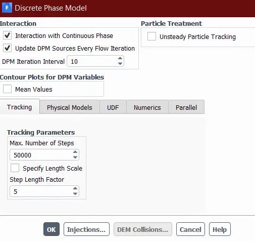
Injection: Surface injection type, Inert, Anthracite material with particle sizes as by varying cases and x-velocity 10m/s
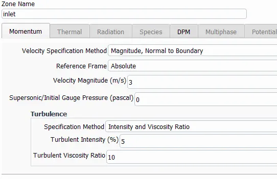
Boundary Conditions:
Inlet velocity 3m/s, Reflect
Wall: Reflect
Outlet1: Escape
Outlet 2: trap
- Results:
Case 1) Constant velocity different Particle size
A) Particle size of 3μm
Tracked Particles

Efficiency Of the Cyclone seperator for Particle size of 3μm =(Escaped + Trapped)/tracked
=261/435
=0.6
=60%
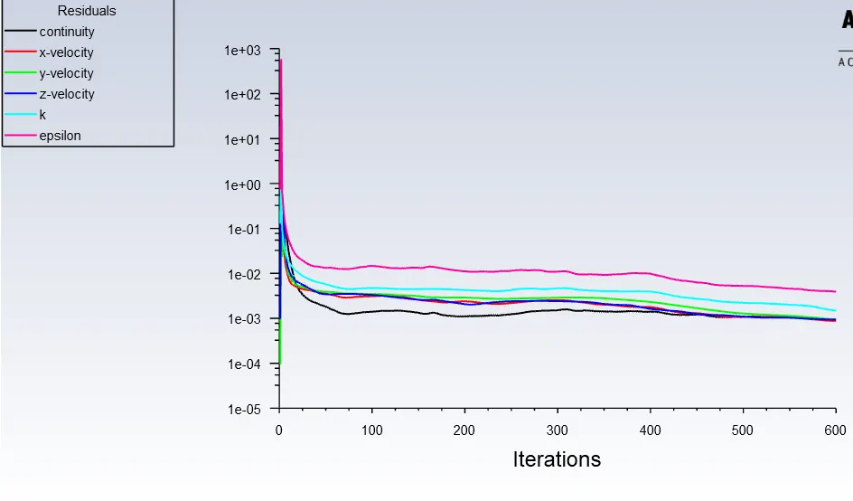
Residuals:
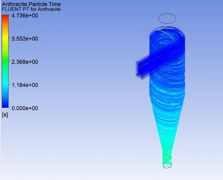
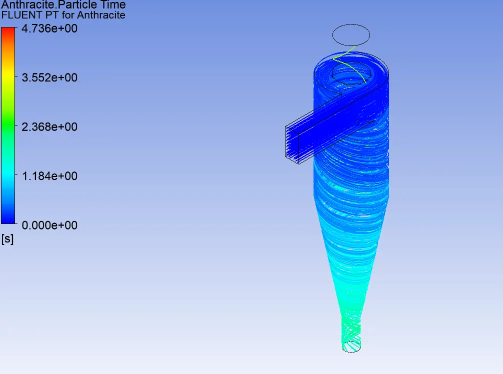
Particle Time Plot for 3 μm
Vortex Form Plot:
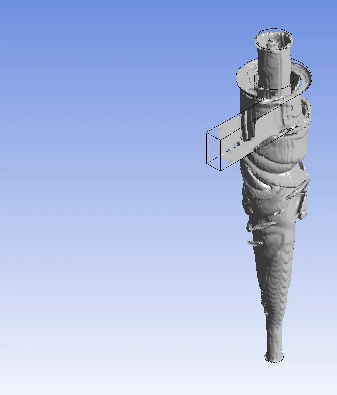
Mass flow Rate:
Inlet:0.018375 [kg s^-1]
Outlet 1: -0.01629 [kg s^-1]
Outlet 2:-0.00206398 [kg s^-1]
B) particle size 4μm
Residuals plot:
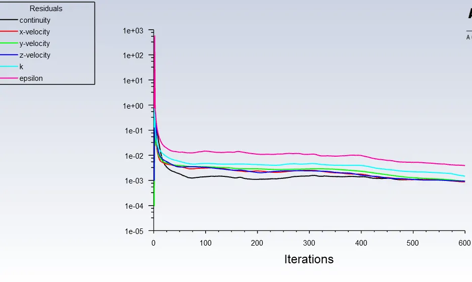
Particles Tracked

Seperation Efficiency Of the Cyclone seperator for Particle size of 4μm =(Trapped+ Escaped) /tracked
=323/435
=0.7425
=74.25%
Plot for vortex
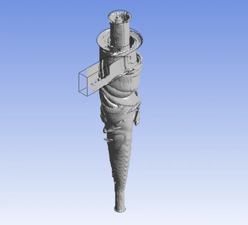
Mass flow Rate:
Inlet:0.018375 [kg s^-1]
Outlet 1: -0.016293 [kg s^-1]
Outlet 2:-0.0020654 [kg s^-1]
C) for particle size 5μm
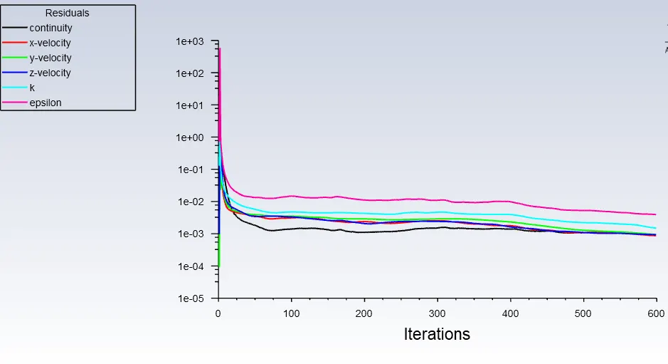
Residual plot:
Particles tracked

Efficiency Of the Cyclone seperator for Particle size of 5μm =(Trapped+escaped) /tracked
=372/435
=0.855
=85.51%
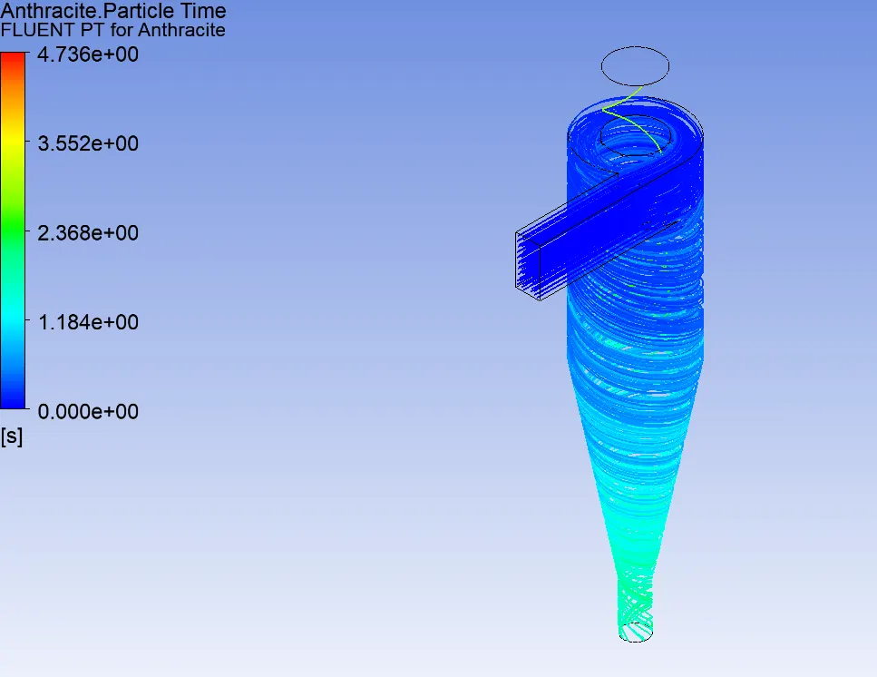
Particle plot:
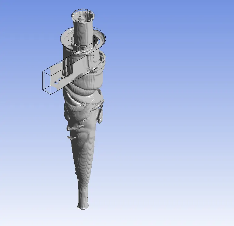
Vortex plot:
Mass flow Rate:
Inlet: 0.018375 [kg s^-1]
Outlet 1: -0.01629 [kg s^-1]
Outlet 2:-0.00206398 [kg s^-1]
Case2 ) Varying velocity but with fixed Particle size 3μm:
- CaseA) Inlet velocity 1m/s:
Tracked Particles:

Efficiency Of the Cyclone seperator for Particle velocity of 1m/s with particle size 5μm =incomplete /tracked
=271/435
=0.622
=62.29%
Pressure drop=poulet2-pinlet pinlet=1.5651354pa, P outlet1=0pa ,P outlet2=-0.0001871903 pa
Pdrop1 =P inlet-P outlet1=1.5651354
Pdrop2 =P inlet-P outlet2=1.5651354-(0.0001871903)=1.56503 pa
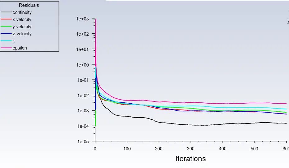
Residuals:
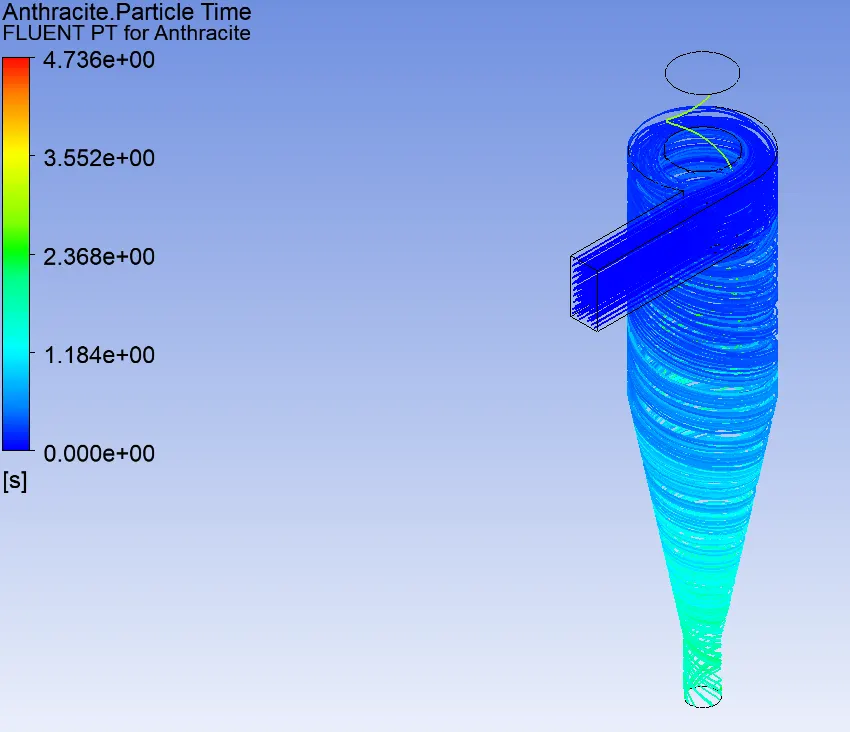
particle flow time plot:
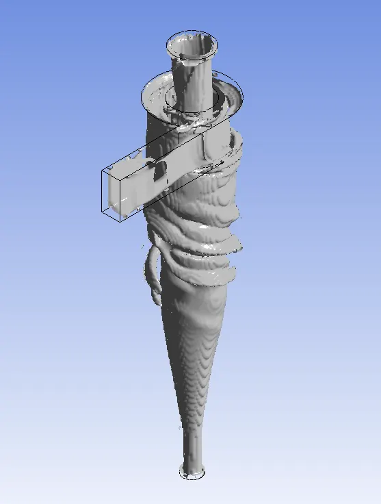
Vortex plot:
Mass flow rate:
Inlet: 0.006125 [kg s^-1]
Outlet 1: -0.00501626 [kg s^-1]
Outlet 2: -0.00110544 [kg s^-1]
- Case B) inlet velocity 3m/s
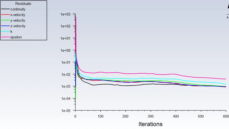
Residuals:
Particles Tracked

Efficiency Of the Cyclone seperator for Particle size of 5μm =Trapped /tracked
=372/435
=0.85517
=85.517%
Pressure drop=poulet2-pinlet pinlet=20.598824pa, P outlet1=-0.016231418pa ,P outlet2=-0.029992223pa
Pdrop1 =P inlet-P outlet1=20.598824pa-(0.016231418pa)=20.5825pa
Pdrop2 =P inlet-P outlet2=20.598824pa-(0.029992223pa)=20.56pa
Particle plot:
Vortex plot:
Mass flow Rate:
Inlet: 0.018375 [kg s^-1]
Outlet 1: -0.01629 [kg s^-1]
Outlet 2:-0.00206398 [kg s^-1]
- Case C)Inlet velocity 5m/s
Particles tracked:

Seperation Efficiency Of the Cyclone seperator for Particle size of 5μm =(Trapped + escaped)/tracked
=374/435
=0.85977
=85.997%
Pressure drop=poulet2-pinlet pinlet=59.556802pa, P outlet1=-0.042484804pa ,P outlet2=-0.18327125 pa
Pdrop1 =P inlet-P outlet1=59.556802pa-(0.042484804pa)=58.957pa
Pdrop2 =P inlet-P outlet2=59.556802pa-(0.18327125pa)=58.8167pa
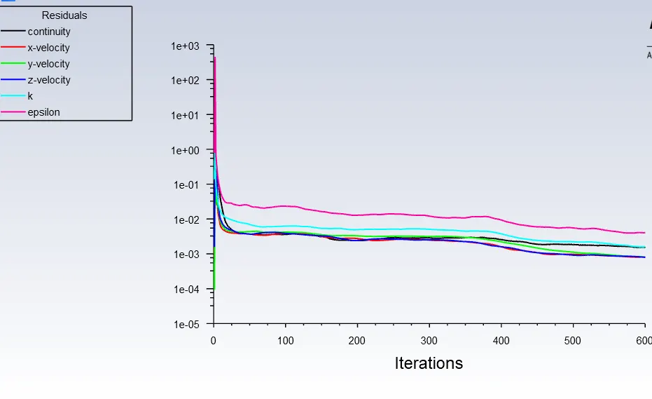
Residual plot:
Particle flow time plot:
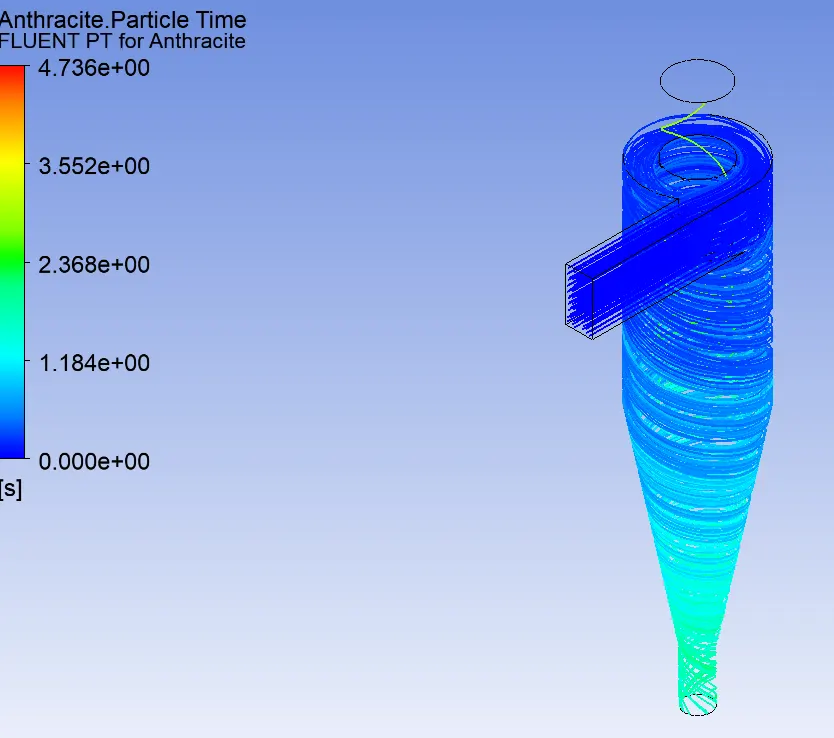
Vortex plot:
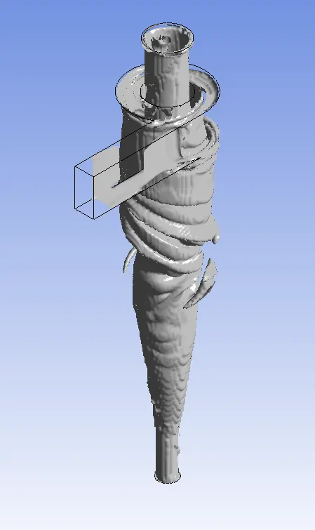
Mass flow rate:
Inlet:0.030625 [kg s^-1]
Outlet1:-0.0280447 [kg s^-1]
Outlet 2: -0.0025622 [kg s^-1]
- Conclusion: As Particle size increases the separator efficiency of the Cyclone separator increases. Also as the velocity of the inlet(both) increases the efficiency seems to increase to a point, but considering the case of velocity 3 m/s and 5 m/s for particle velocities, the Separator efficiencies seem to differ by a mere fraction. Finally, separator efficiency comes to the number of particles that are tracked and escaped. To capture more particles with varying particle sizes we need finer mesh sizes.