Shell Meshing for a Car Hood Model using ANSA
Report on Meshing of the Given Car Hood Model.
- Aim: To extract the mid surface of the given car hood model and perform meshing on it with the given Mesh Quality criteria.
- Procedure: 1. The very first step upon receiving the model is the geometry clean up. I used the checks manager option on the software. I selected the Geometry option under Checks Manager.
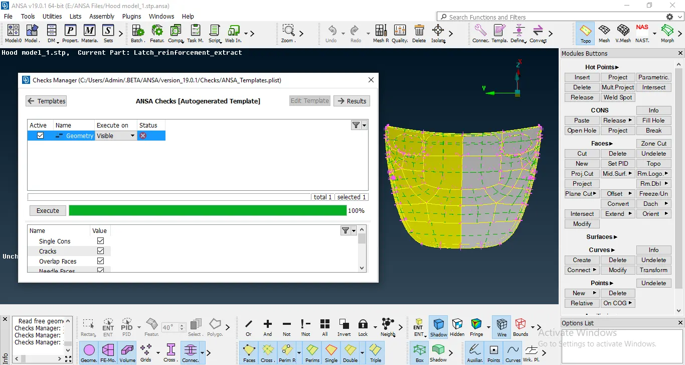
Image of the model before the Geometric clean up was performed.
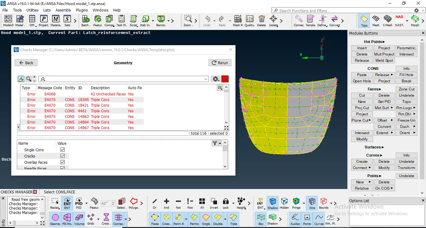
The model needs geometric clean up after it puts out all the different errors that are present in the model.
On performing the Geometric clean up,
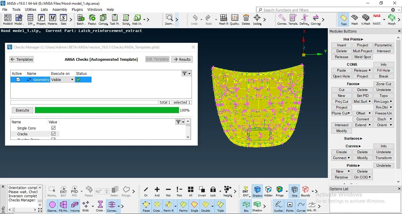
This is the model after the geometric clean up was performed.
2. After performing the Geometry clean up, I checked for the orientation of the geometry. Then later, I underwent with the extraction of the mid surface of the different sub-components in the model. The method I have used for this process is the command of Offset under Faces which comes under the tab of Topo. I understand that as a novice to the software, this option will give me a better understanding of the model and the various commands and the boolean operations that can be used.
To use the offset command, I used the Select-front only option, and selected all the surfaces of the sub component. After the Mid-surface of a component is taken, I assigned a property to that face using the SetPID command under the Macros option.
For example: Here are two images of the lower part of the hood before and after mid surfacing. (I have taken the midsurface of the three latches seperately hence the latches are not visible in the midsurface)
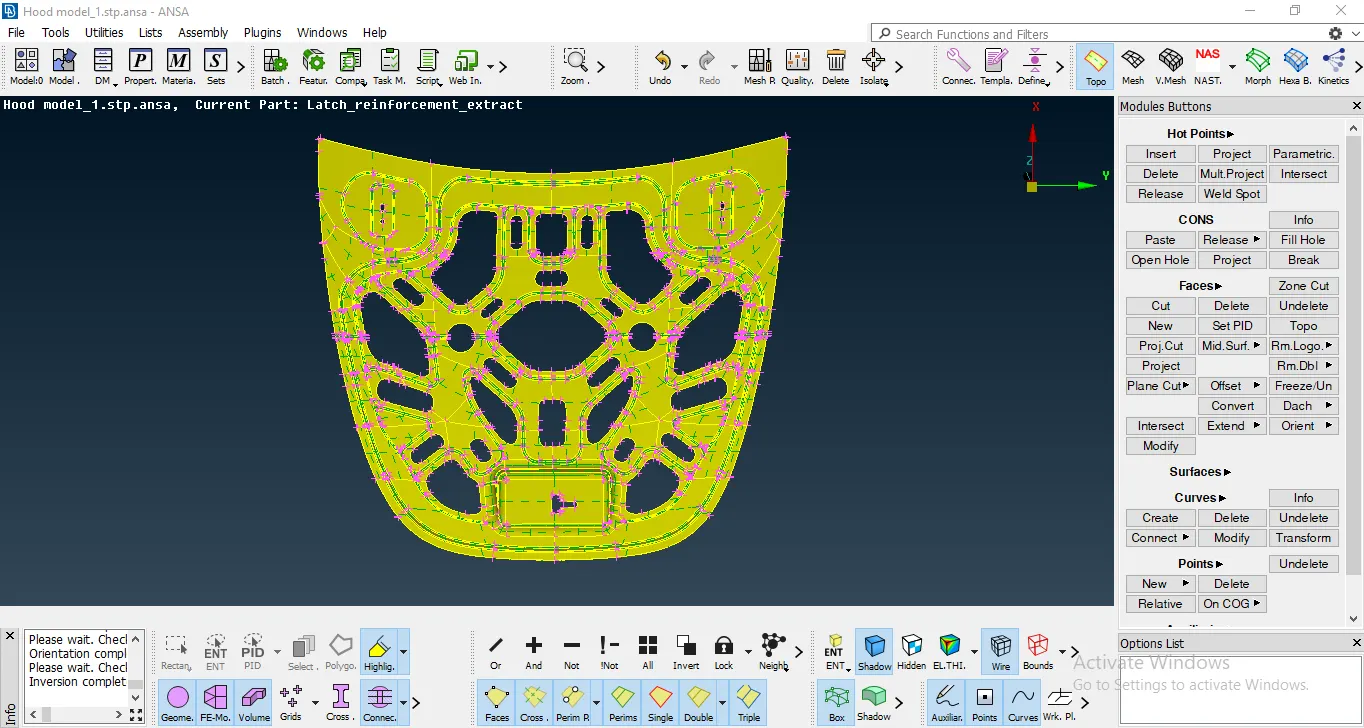
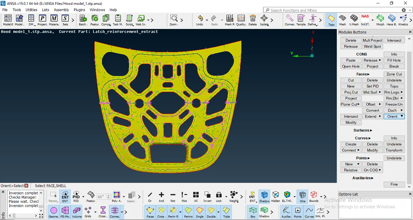
After checking and resolving for the presence of any triple cons, we proceed for the meshing of the subcomponent.
3. For meshing, we need to firstly divid the sub-component into further more areas to mesh by using the Faces cut option. I feel that this method will yeild better mesh in terms of the mesh flow produced.
Now to proceed with meshing, We firstly need to set the Perimeter Elemental Nodal Distance as given in the Quality index.
For this we need to select the Length command in Perimeter option. We then need to feed in the Quality criteria as given.We can change the colour and the visibility cirteria of the Quality parameters as our need and after feeding in the Quality criteria, we can proceed for meshing.
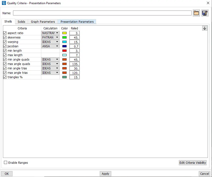
Quality Criteria Index
4. Now to mesh the sub-component, I opted for the Best command under Mesh Generation. The command is a hybrid option and gives the best mesh flow possible considering all the variables like geometric shape of the component and Quality criteria that was given.
And after a mesh was formed there, we need to check for any opposite tria elements and rotating quads. If these elements are present in the model, we need to work on them and remove them. We also need to keep the tria element percent to a minimum as it makes the entire geometry much more stiffer.
After obtaining a mesh for the sub-component, I used the Reconstruct command to improve the mesh flow and reduce the tria elements in the mesh generated. Even after this, the checking for the opposite tria and rotating quads is done and resolved accordingly.
5. After resolving all the problems, I checked for any Quality issues that might be present in model and solve them using different commands like reconstruct, reshape, or move. To see for any Quality errors, we need to activate the Hidden mode and see the quality issues according to the colours we set.
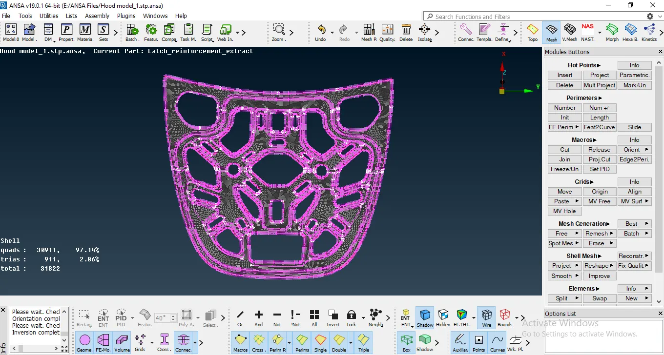
Final Mesh for a sub component
After solving for the quality issues and reducing the tria percentage as much as possible, the component is finally meshed.
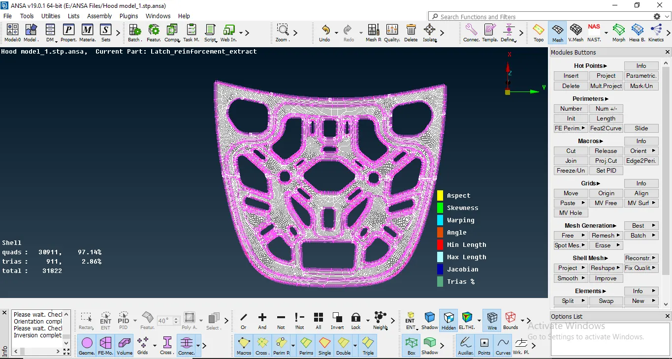
Zero Quality Issues in the sub component
- Learning Outcomes: 1.The primary learning outcome from this challenge is that I learned how to operate around the software.
2. I also understood the basic functionalities of all the different available and hidden commands and options.
3. How to properly extract Mid surface for a component using the Manual Midsurfacing method.
4. How to reduce tria elements.
5. I understood how to remove all the unnecessary elements and work on the model.
6. How to resolve different quality issues in the mesh.
- Conclusion: In conclusion, I would like to state that Manual Midsurfacing using the Faces offset option is the method to extract the mid surface of the component as a beginner and that I have learnt to solve for any Geometric and Mesh Quality Parameter issues.