Connections on a Rear Door Model using ANSA.
Report on Connections on the Rear Door Model.
Aim: To make the appropriate connections on the given Rear Door model.
Procedure: 1. The very step upon receiving the model is to identify the necessary connection points on the model.
2. The first part where I made a connection was the Door Hinge. To make this connection here, I firstly created a 3D point and then converted it to a bolt. Now to make a 3D point, I selected the Points option under the Topo tab and created the point on the Center of Gravity(COG) of the mating point of the two parts. Then later I converted the point to a bolt and for this, I used the Convert option and selected the 3D point and converted it to a bolt.
After converting it to a bolt, I then switched on the Connection manager and then i defined the parts where I needed the bolt connection in the Part 1 and Part 2 in the model. After this, I gave in other important inputs such as the search distance and the zones for the connection and then later I applied the FE and realized the connection.
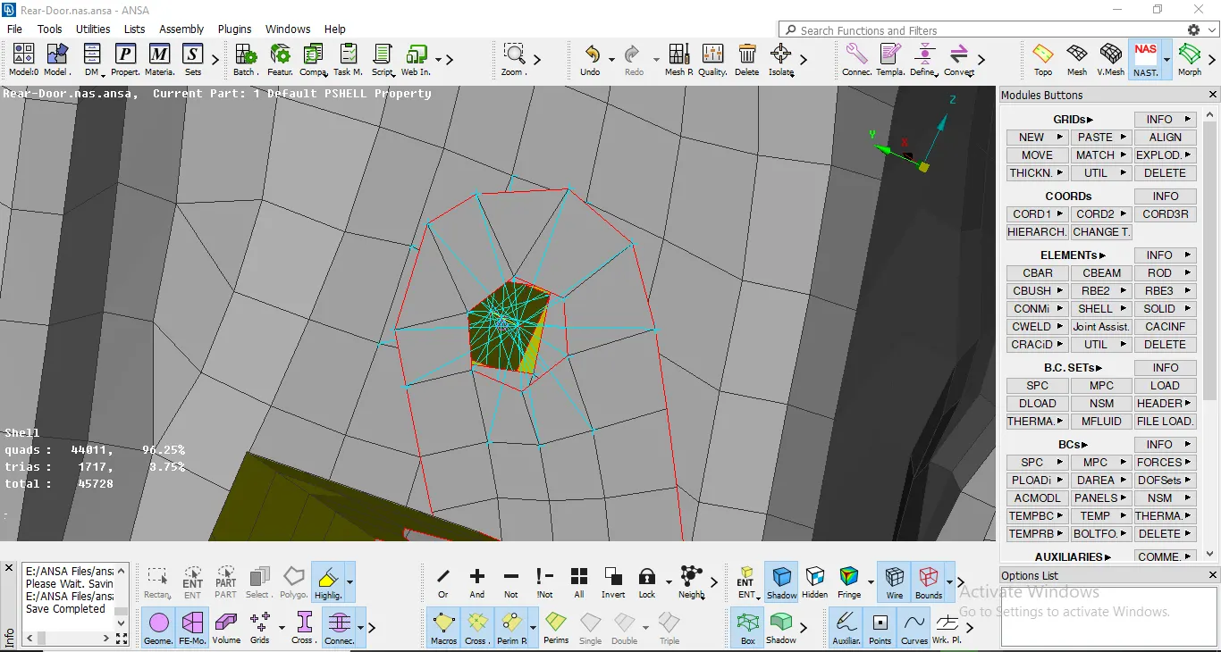
Bolt connection
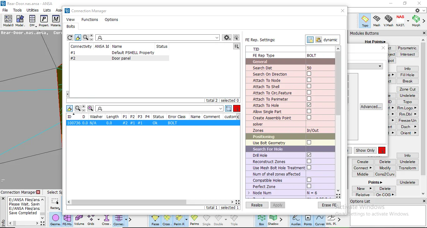
Bolt Connection Manager
2. After getting done with the hinges, I moved on to make the connection for the door flange. For this, I used the RBE2 connector. I used the Many nodes option and selected the Hole. Now, since the door was going to be rotating along the global Z-Axis, I altered the Degree of Freedom accordingly.
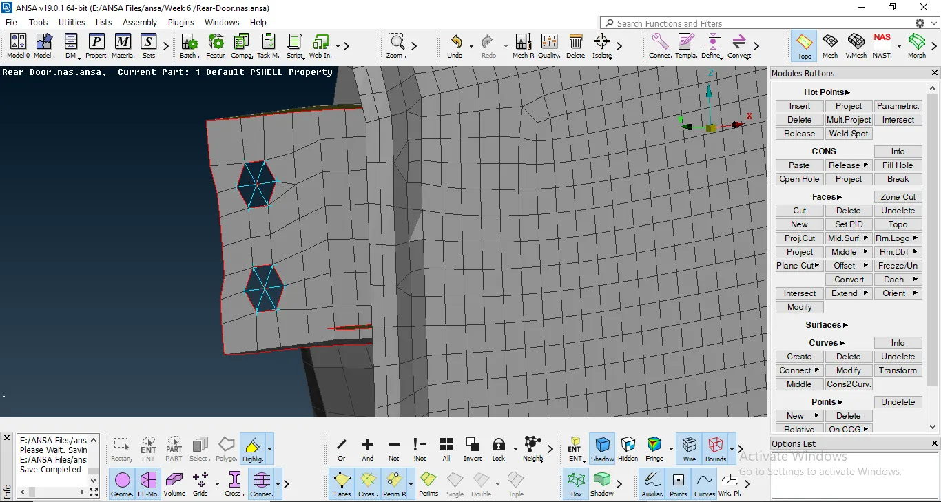
Door Flange
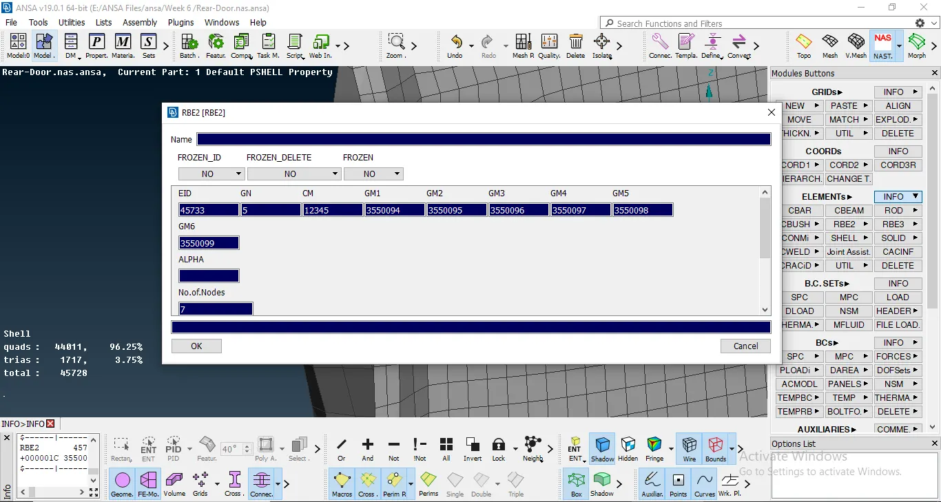
Door flange connection properties.
3. Another important part where I made the connection was the Door handle. I used the RBE2 connector and made the connection. I also connected the two master nodes with another RBE2 connection.
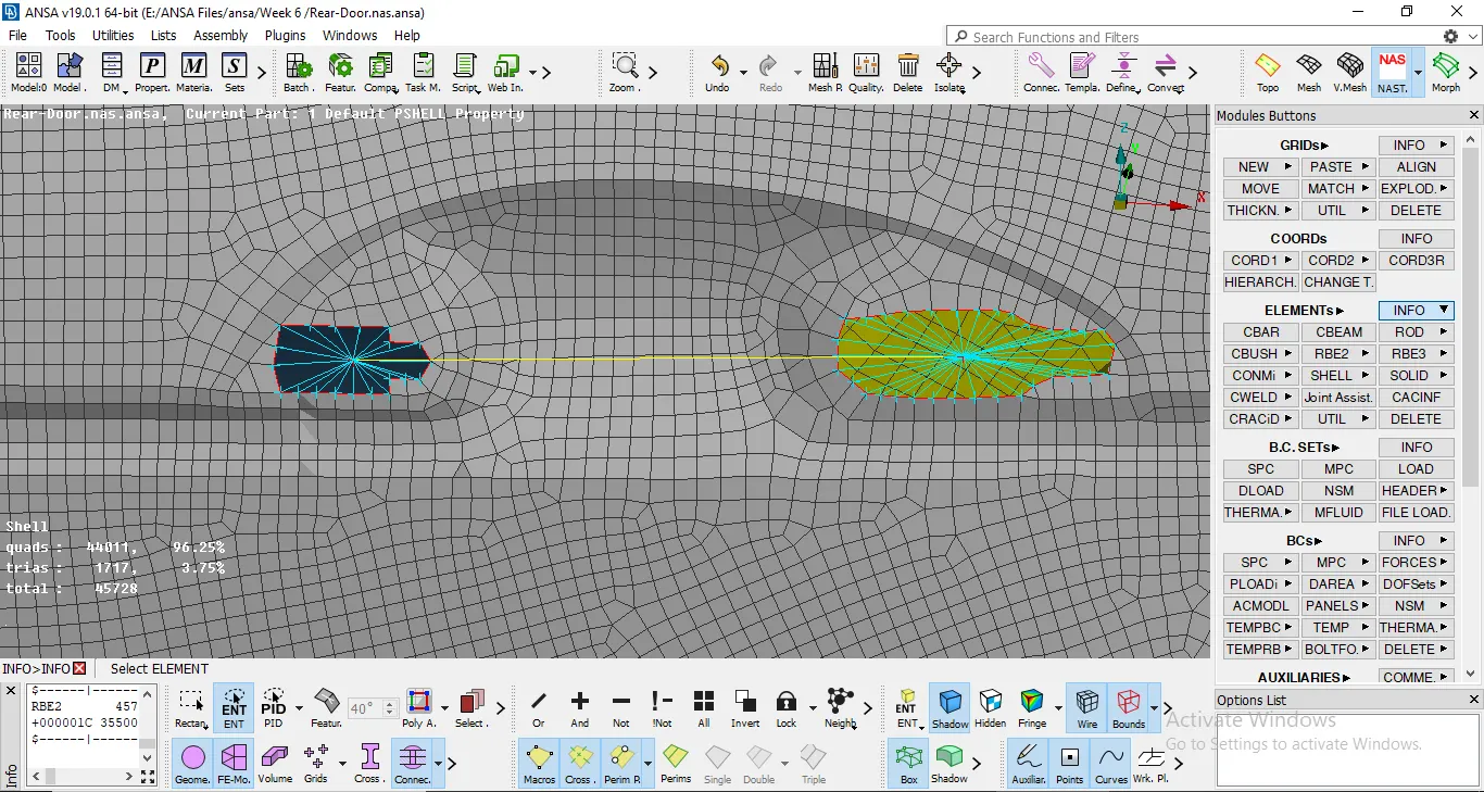
Door Handle Connection.
4. Another type of connection I used, is the CBUSH connector between the window and the main door body panel.THe CBUSH connector is used because of the presence of a rubber strip between the two components. This rubber strip acts as a Weather shield and as an elastic component. So because the connection is going to need a certain few properties assigned to it, I used the RBE3 connection instead of RBE2.
To proceed with this, I used the Feature2Curve option and then converted the edges of the window to curves. After this, I connected all the Curves using the Curves connect: Multi option.
After the curves are connected, I converted one curve at a time to a spotline. Then for each spotline I used the RBE3-CBUSH-RBE3 connectors and defined the two parts where I needed the connection to happen. For this I changed the part 1 and part 2 definition in the Connection manager. Later I gave the various inputs like Search Distance and selected the Keep all Branches option and realized the connection.
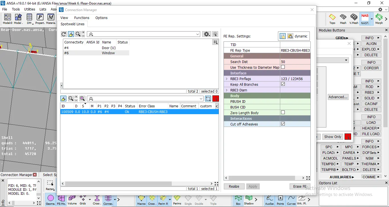
CBUSH Connection manager.
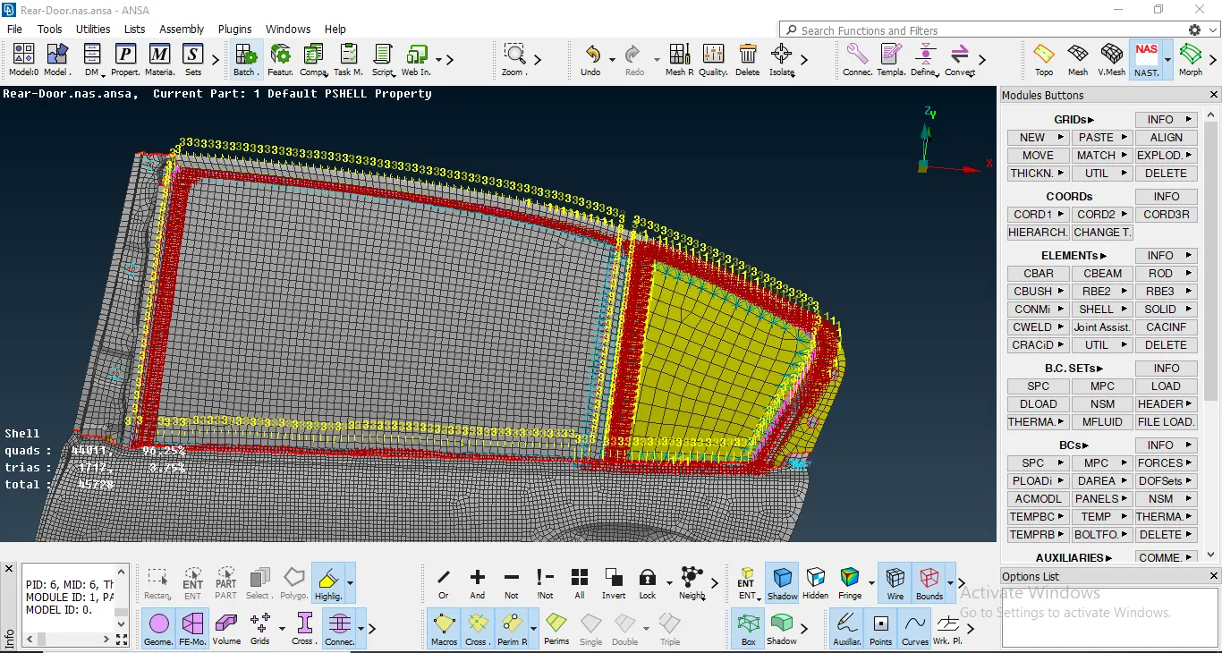
CBUSH connections made on the window.
Learning Outcomes: 1. How to make connections according to the geometry.
2. How to make a RBE2 and RBE3 connections.
3. How to make a bolt and CBUSH connection.
4. How to use different settings under all these connections.
Conclusions: I would like to conlude that I have learnt how to make proper connections and use them in according to the given geometric model.