Shell Meshing for a Bottle Cap Model using ANSA.
Report on Meshing of the given Bottle Cap Model.
- Aim: To successfully extract the mid surface and mesh the given Bottle cap Model with the given Quality Criteria.
- Procedure: 1. The first step upon obtaining the model is the procedure of Geometry clean up. For this step, I used the Checks Manager command. Then I selected the Geometry option under this command.
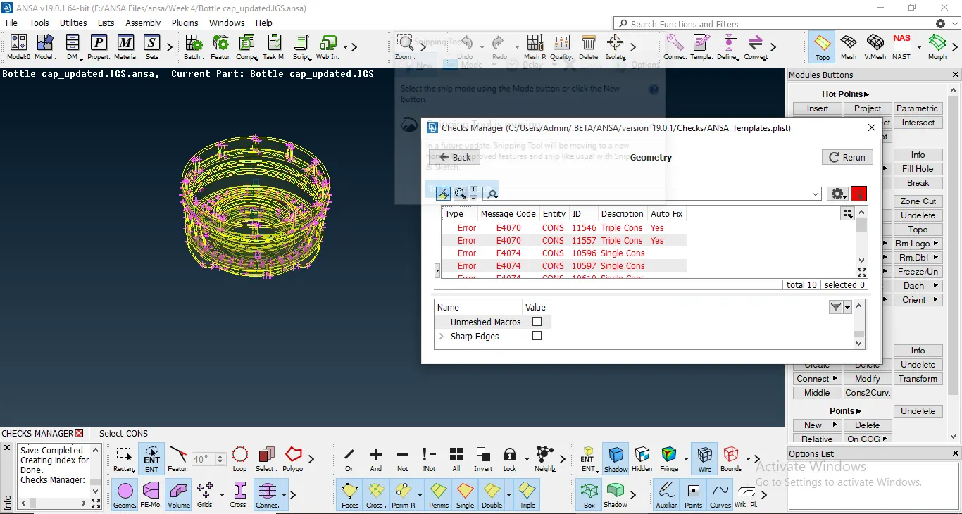
Model Before Geometric clean up.
On performing the Geometric clean up, we get a clean model ready for mid surface extraction,
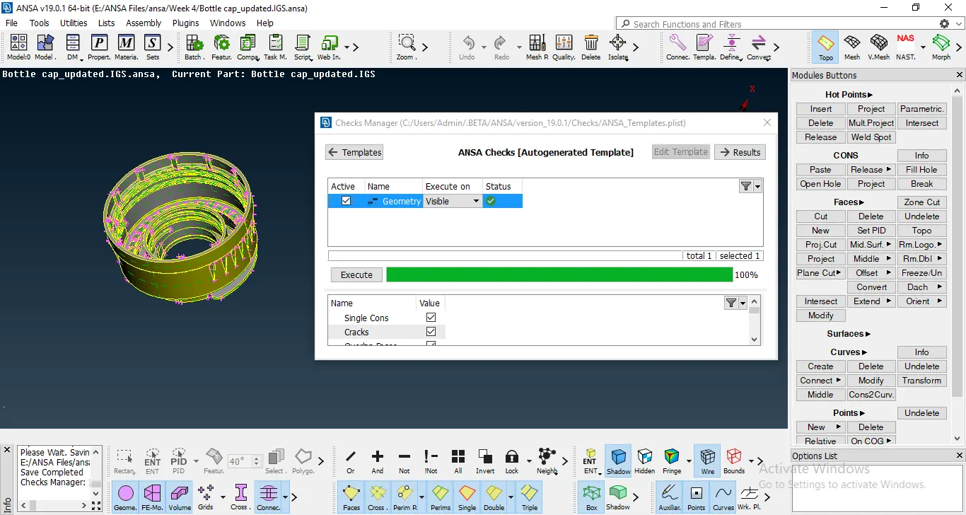
Model after Geometric Clean up
2. After Geometric Clean up, I checked and corrected the orientation of the model. After the Orientation was done, I underwent with the extraction of the mid surface of the entire component. There are numerous ways and methods to extract the mid surface for different surfaces in the entire component. The Offset command can be used for surfaces with a uniform thickness throughout. Other commands include using the Faces middle option or by even creating curves for a certain features.
For example: For the threads on the surface, we extract the middle curve using the Middle option under curves of the thread. Then we project the curve on the mid surface and create a new surface using the Coons option under the New surface command.
. 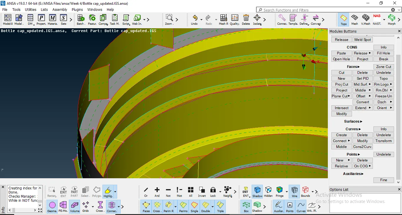
Mid surface of the thread.
The usage of any command depends on the geometry and if the thickness is varying for the associated surface.
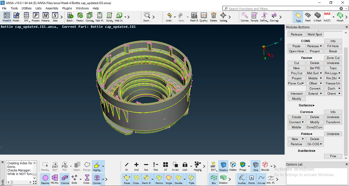
The model before Extraction of mid surface
Using all these commands, we extract the mid surface for the entire model. I chose these options over Auto-midsurfacing, because as I understand Manual midsurfacing will help me better understand the surface and geometry of a particular model and also aide me to understand the various commands for the same.
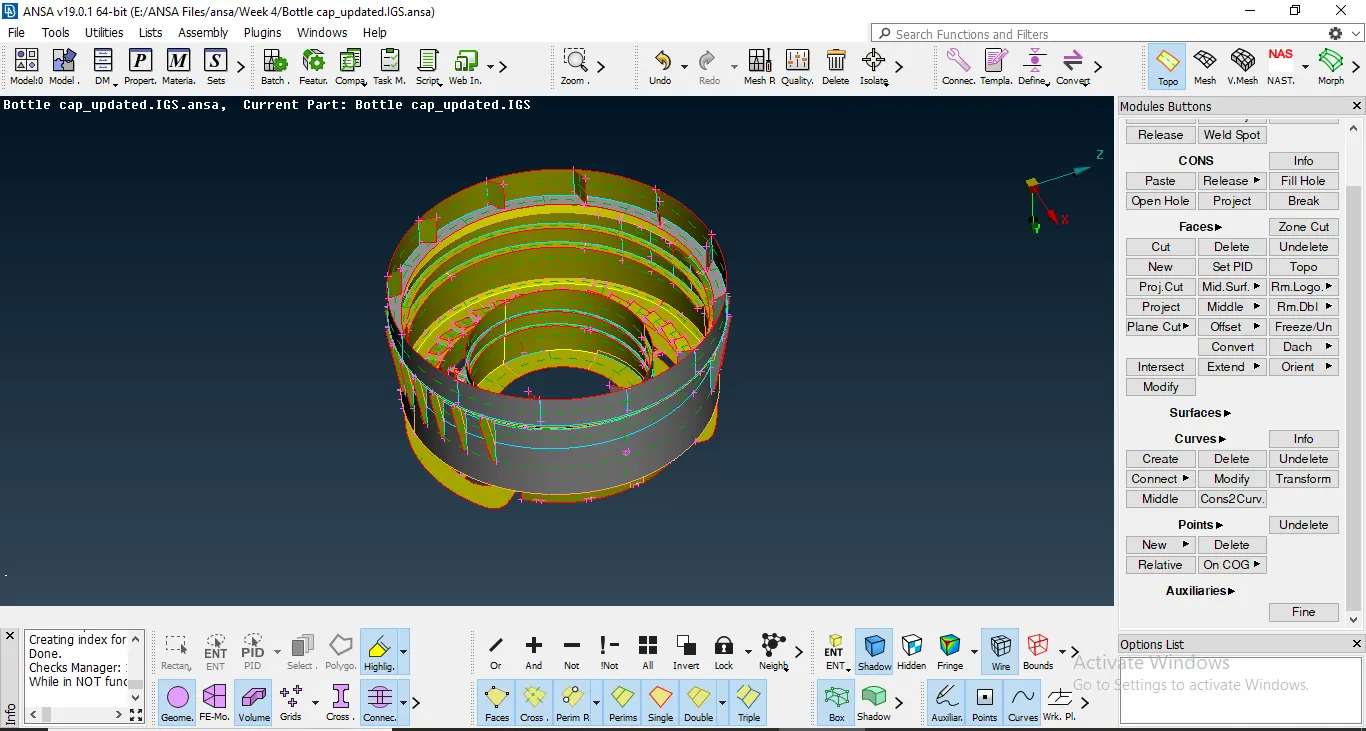
The model after mid surface extraction.
After doing the necessary extensions and creating the right mid surface, we can proceeding for the meshing of the model.
3. For meshing, I divided the component into sub areas by using the Faces cut option. I understand that this method will give better mesh flow and lesser number of trias in the component.
Now to proceed with meshing, we need to set the Perimeter Elemental Nodal Distance as mentioned in the Quality Index. To do this, I used the Length command in Perimeter option. After this, we feed in the Quality criteria as given. We can change the visibility criteria and also the colour of the respective quality criterias.
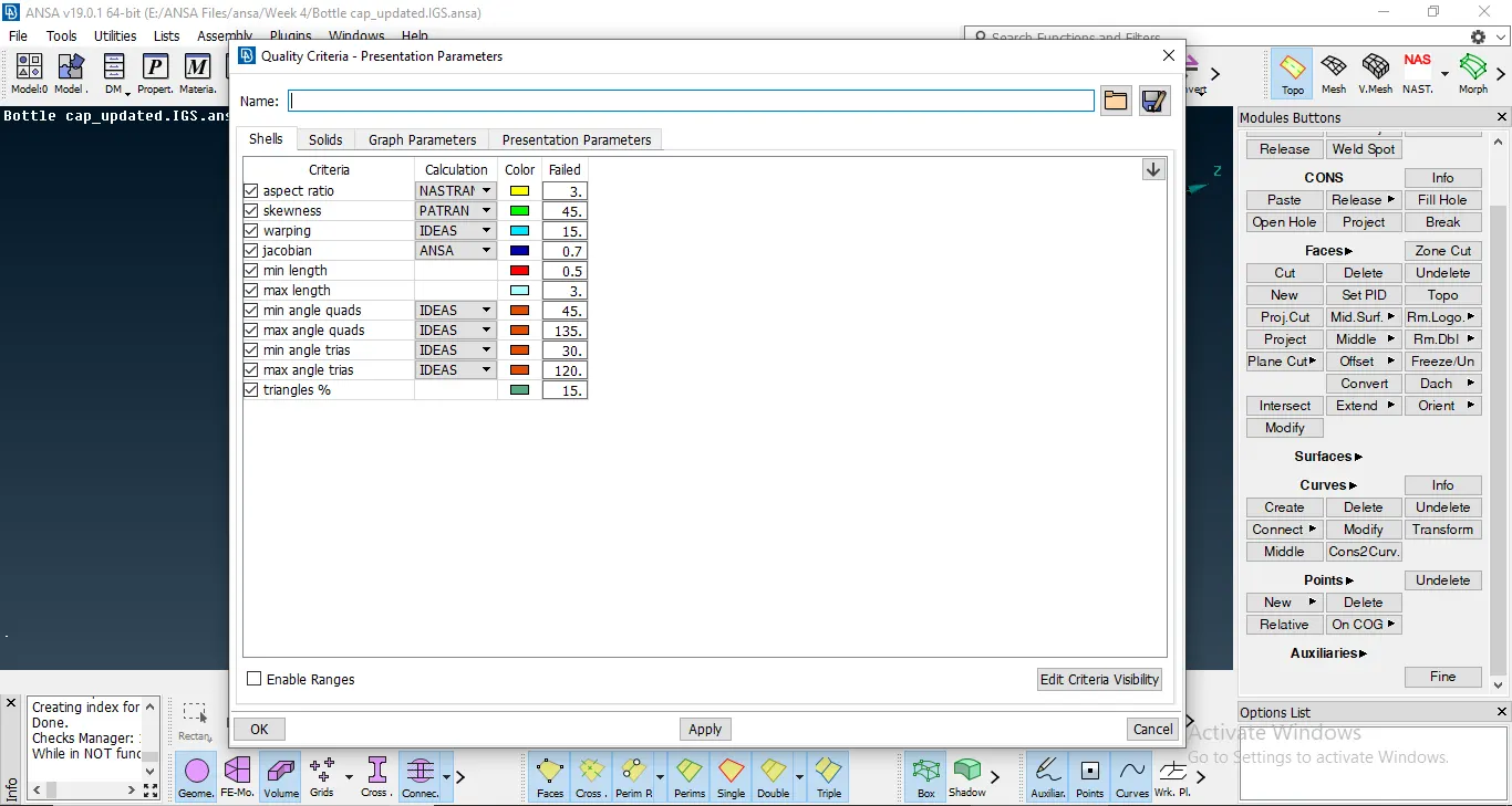
Quality Criteria for the model.
4. Now, to mesh the component, I chose the Best command under Mesh Generation. The command is an hybrid option that gives out the most appropriate mesh according to the geometric shape, target length and the Quality criteria index as given by the user.
After a certain mesh is formed, I checked for any opposite tria elements and Rotating quad elements in the mesh. The presence of the elements hampers the quality of mesh and makes the model more rigid. We need to work on removing these elements by using the various commands like, Paste, Split etc. I even used the Reconstruct command to improve the Mesh flow and reduce the Tria elements in the mesh.
Following the mesh generation, I assigned the thickness for the various parts of the component that have varying thickness. To do this, I set a new PID for every component with common thickness. To go through with this process I used the Set PID command under the Macros option and selected the components with similar thickness.
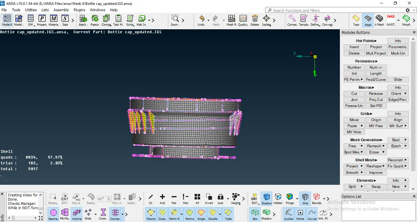
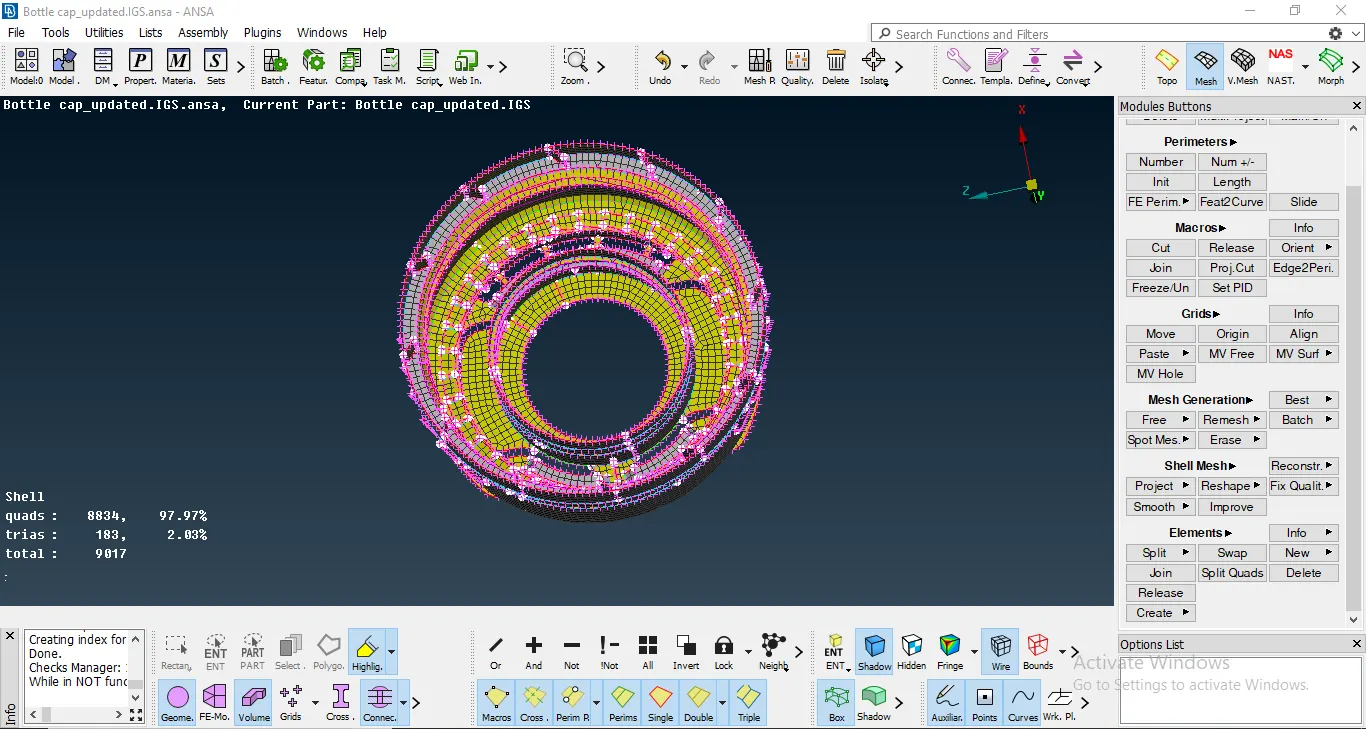
The component after Meshing
5. After checking for any of the above elements, we go on to remove the the quality errors that are formed in the mesh. I activated the Hidden to view for all the errors. Now, to solve these errors, I used the commands like Reconstruct, reshape, more etc. After resolving most of the formed errors and not disturbing the mesh flow the component is finally meshed.
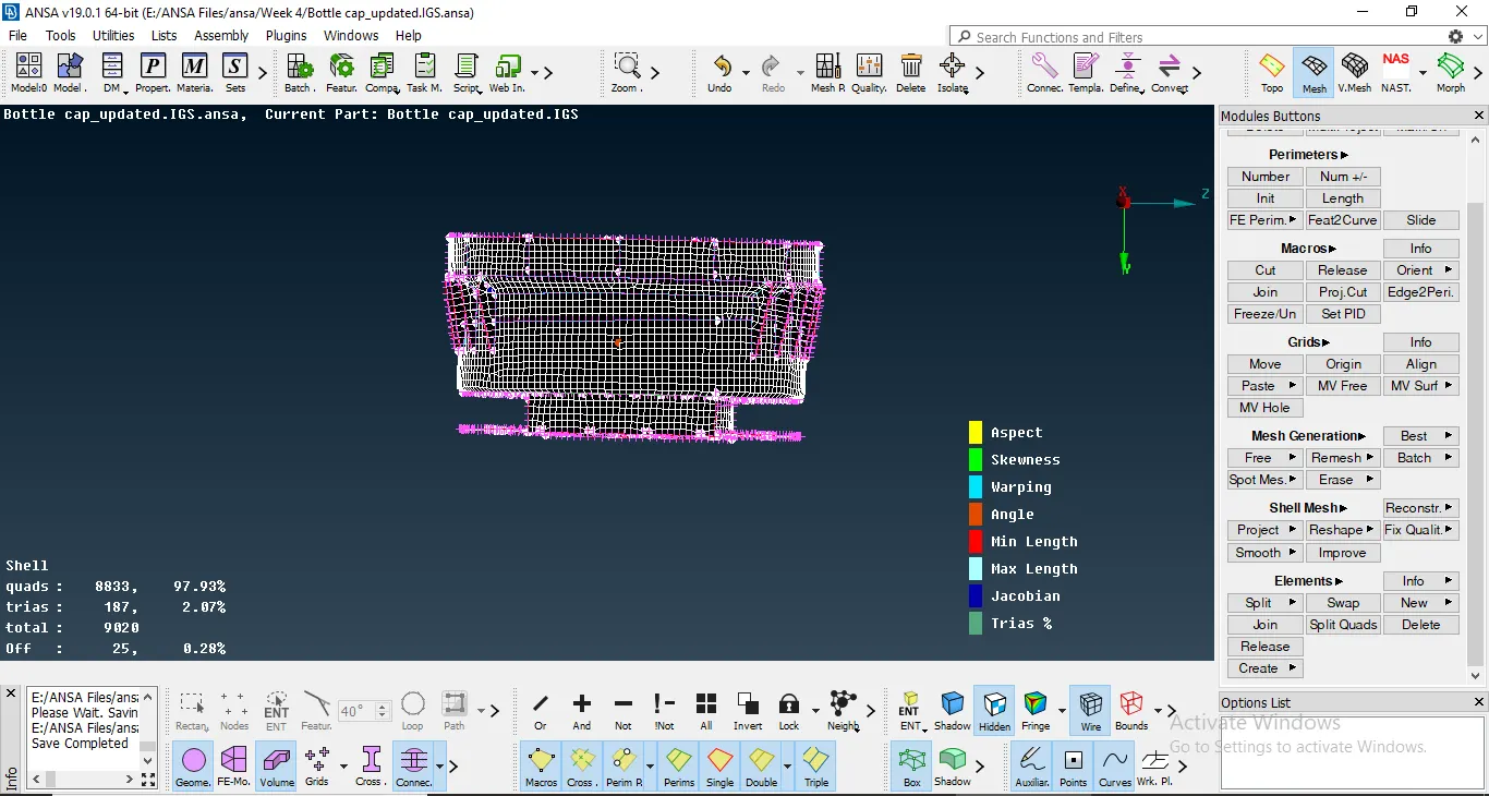
After Resolving the Quality Criteria
- Learning Outcomes: 1. How to extract proper midsurface for a model with varying thickness.
2. Different Manual mid surface extraction commands like, Faces offset, Faces middle etc.
3. How to operate with the Curves command.
4. How to assign thickness for the given model.
5. How to extract mid surface for threads and teeth on the component.
6. Learnt how to extend a con onto a surface.
- Conclusion: In conclusion I would like to state that Manual mid surfacing for such components can sometimes yield a better mid surface that Auto mid surface generation and that I have learnt various new commands to aid the Mid-surfacing procedure.