Week 8 - Simulating Cyclone separator with Discrete Phase Modelling
Aim: Perform analysis on cyclone separator and calculate separaion eficiency and pressure drop.
Cyclone separator
It is a device used to separate particles diameter ranging from 2.5 to 10 micrometers. These device utilize the principleas of centripugal force seperating particles.
Emperical methods used to calculate cyclone separator efficiency
Li and Wang model
This modl considers particle bounce or re entainment and turbulent diffusion at the cyclone wall. A two dimensional analytical expression of particle distribution obtained.
Lozia and leith model
This model resdesigned version of barth model, which is based on forced balance, The model assumes that a particle carried by the vetex sustains the influence of two forces.
Koch and licht model
This theory recognised turbulent nature of cyclones and spreading of residence periods within cyclone. This model defined particle motion in the entry and collection location
Lappel model
This model based on force balance with exception of the flow resistance. lappeled assumed that particle entering the cyclone is evenly distribute across the inlet opening The particle that travels from half inlet width to the wall in the cyclone is collected with 50% efficiency.
Simulation steps
Geometry preparation
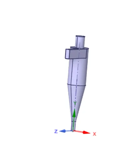
Import given geometry inti spaceclaim and open prepare use volume extcract tool extract volume and hide soid body and do suppress physics.
Mesh
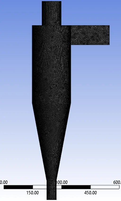
After geometry preparation open mesh window and do fine mesh with element size 6mm. we doing fine it helps to give better results
Setup
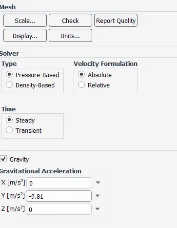
After mesh open fluent window, used steady time, pressure based solver and absulute velocity, and check gravity box and given a value -9.81 in y axis
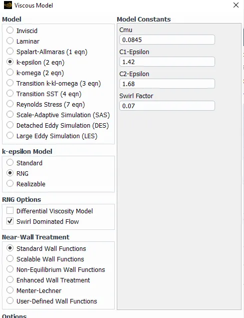
In viscous model select k epsolon with RNG and swirl dominated option is slected with standard wall function
Discretisation: it is process of tranfering continuous functions, models, variables and equations into discrete conterparts
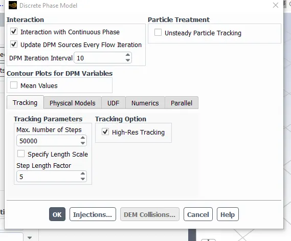
Discrete phase model
It is swicthed on because there is particle flow along with continuous flow.
Ireration with continuous flow is checked because there is combined flow of descrete and continuous flow of particles.
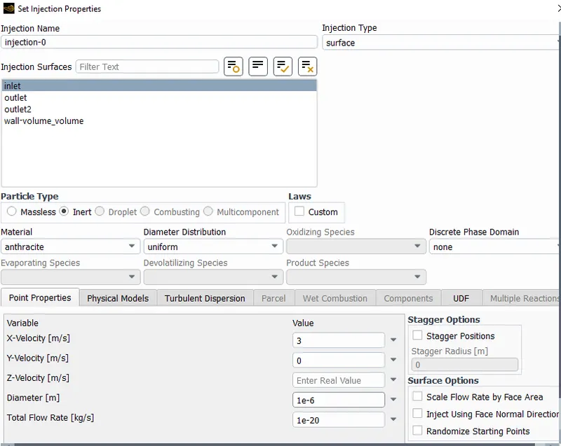
injections of particales setup is use to define thae particale velocity and size of material anthracite selected.
Boundary condition
Inlet and wall - reflect
outlent top- Escape
Outlet bottom - Trap
Slected solution method
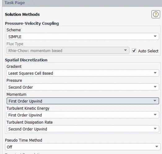
Define results what we want
Case 1
In case 1 velocity is 3m/s and particle size is varying
Particle size 1 μm
Residuals
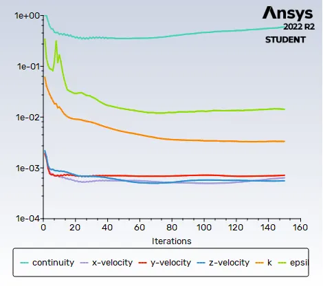
Particle time
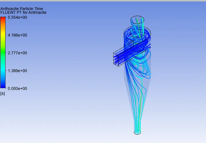
Separation efficiencny= Number paricles trapped/total number of particle tracked

120/288= 41.6%
Particle size 2μm
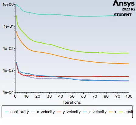
Residuals
Particle time
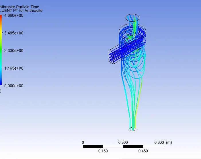
Separation efficiencny= Number paricles trapped/total number of particle tracked

111/288 =38.5%
Particle size 3μm
Residuals
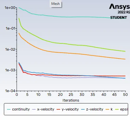
Particle time
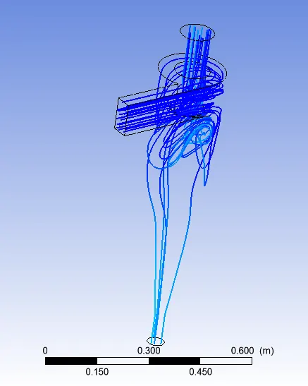
Separation efficiencny= Number paricles trapped/total number of particle tracked

85/288 = 29.5%
Case2
Particle size is constant 5μm varying velocity inlet
1m/s
Residuals
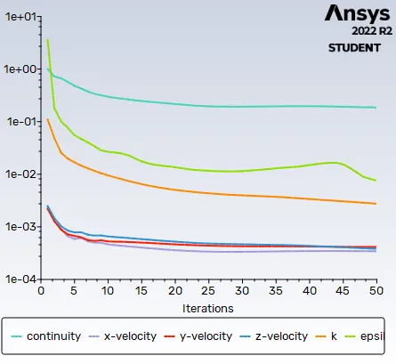
Particle time
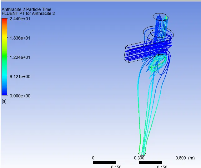
Velocity contour
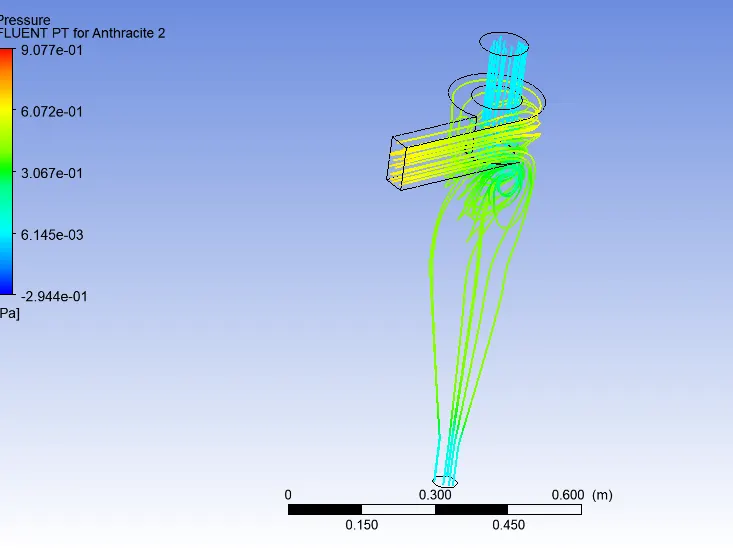
Separation efficiencny= Number paricles trapped/total number of particle tracked

88/288=30.5%
velocity 3m/s
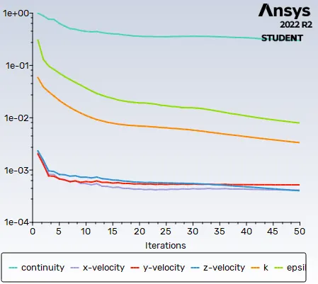
Residuals
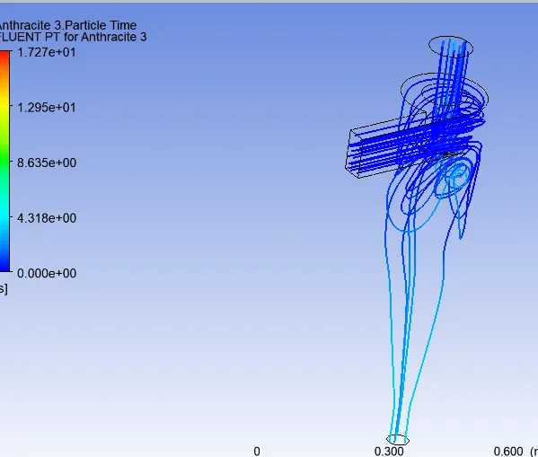
Particle time
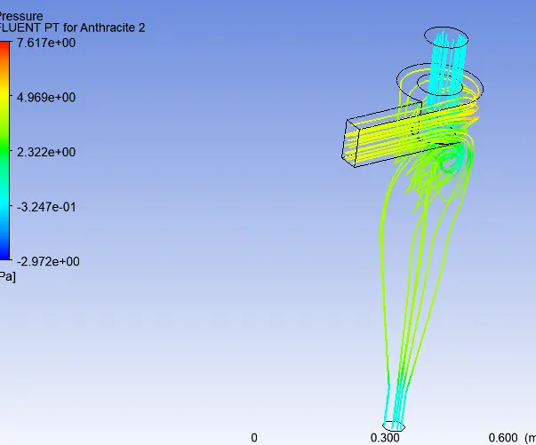
Pressure contour
Separation efficiencny= Number paricles trapped/total number of particle tracked

93/288= 32.29
Residuals
Particle time
Pressure contour
Separation efficiencny= Number paricles trapped/total number of particle tracked

90/288=31.2%
Results
Case 1 velocity constant 3m/s
| Particle size μm | Separation efficienncy in % | |
| 1 | 41.6 | |
| 2 | 38.5 | |
| 3 | 29.5 |
Case 2 constant particle size 5 μm
| velocity m/s | Separation efficienncy in % | Pressure drop |
| 1 | 30.5 | 7.619 |
| 3 | 32.5 | 7.619 |
| 5 | 31.2 | 7.619 |
Conclusion
- When we inceasing gradual particle size separator efficiency going down. Velocity play imortant role in cyclone separator
- When we inceasing gradual particle velocity separator efficiency also incrasing.
- Finally analysis on cyclone separator simalation performed succesfully