Simulating Cyclone separator with Discrete Phase Modelling
Aim –
To simulate the flow through a cyclone separator and showing the results for the different particle size and for the different velocities.
we have to run the simulation for the six cases
1)set the velocity constant to 3 m/s and do simulation for the varying size of the particle.
2)set the particle size to constant and simulate for the different velocities.
Cyclone Separator –
Cyclone separators are separation tools that filter flue gases by removing particle matter using the law of inertia. The term "pre-cleaner" refers to a variety of air pollution management technologies that often remove larger bits of particulate matter. One such technology is the cyclone separator. This avoids the need for later, finer filtration techniques to handle larger, more abrasive particles. A multi-cyclone system is one that allows many cyclone separators to run simultaneously.
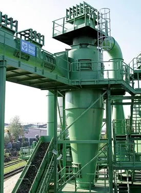
It's crucial to remember that cyclone sizes can vary greatly. The amount of flue gas that needs to be filtered heavily influences the cyclone's size, hence larger operations typically require larger cyclones. For instance, there may be multiple versions of the same type of cyclone, with heights ranging from a relatively small 1.2 to 1.5 metres (about 4-5 feet) to about 9 metres (30 feet), which is roughly the height of a three-story skyscraper.
Working of Cyclone Separators –
Similar to a centrifuge, cyclone separators operate by continuously supplying unclean air. The unclean flue gas is routed into a chamber of a cyclone separator. The chamber's inside generates a spiral vortex that resembles a tornado. The figure below depicts this spiral creation and the separation. It is simpler for the lighter parts of this gas to be impacted by the vortex and move up it since they have less inertia. Larger particles, on the other hand, have more inertia and are less susceptible to the vortex's influence.
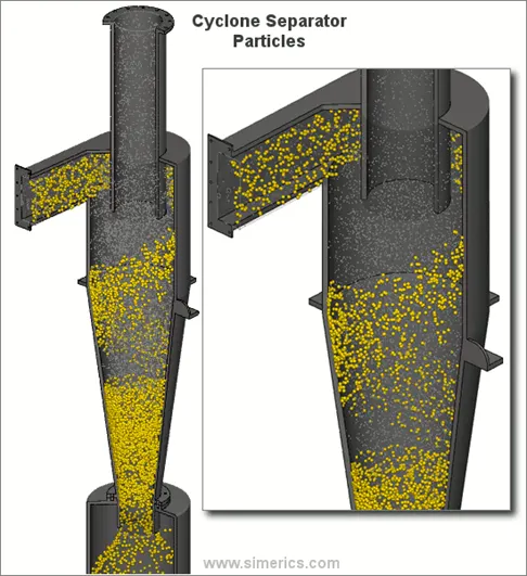
The majority of cyclones are designed to contain and eliminate particles larger than 10 micrometres in diameter. High-efficiency cyclones that are made to be efficient on particles as small as 2.5 micrometres do exist, nonetheless. Furthermore, these separators do not work effectively with very large particle matter. Momentum separators or gravity settling chambers are preferable for particulates smaller than 200 micrometres.
Cyclone separators are among the most affordable particle control equipment. Before the flue gas enters more effective pollution control equipment, they are frequently utilised as a pre-treatment. Cyclone separators can be thought of as "rough separators" because they are used before the flue gas goes through the fine filtration stages.
Effectiveness –
Most of the particulate matter in the flue gas may be removed by cyclone separators, which can do so between 50 and 99% of the time. The size of the particles has a significant impact on how effectively the cyclone separators can remove this material. Less of these particles can be sorted out when there is a lot of lighter particulate matter present. Because of this, cyclone separators perform at their best with flue gases that have a lot of large particle matter present.
Using cyclone separators has a number of benefits and drawbacks. Cyclone separators are advantageous in the first place since they don't require much maintenance and are inexpensive to install. This lowers the cost of operation and maintenance. Second, it is easier to dispose of the removed particle matter since it is gathered when it is dry. Last but not least, these units don't take up much room. Utilising cyclone separators has drawbacks despite being effective. mostly due to the typical models' inability to efficiently capture particles smaller than 10 micrometres and the machines' poor ability to handle sticky or gooey materials
Description of the project statement –
- With varying the particle diameter, at a constant velocity at inlet the flow is simulated. separation efficiency is found out.
- With varying the velocity at the inlet, at constant diameter of the particles, the flow is simulated. separation efficiency and pressure drop in the cases is found out.
Changing particle diameter from 1 micrometer to 5 micrometer, with velocity as 3 m/s
Geometry Setup –
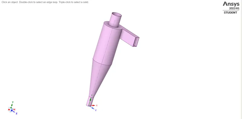
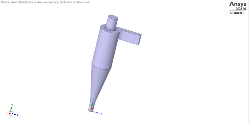
- Select the Fluid flow (fluent) module and begin changing the shape.
- Open Spaceclaim and import the model's step file.
- In order to analyse the fluid flow of the cyclone separator, fluid volume is taken from the geometry using the prepare option.
- Cover over the preceding geometry and suppress the physics because the fluid flow itself is what is important, not the external surface.
Mesh Setup –
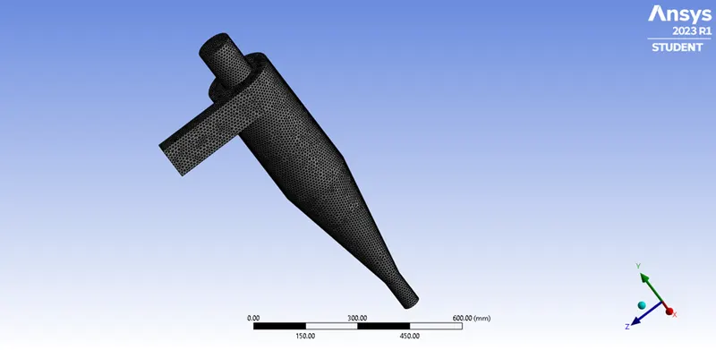
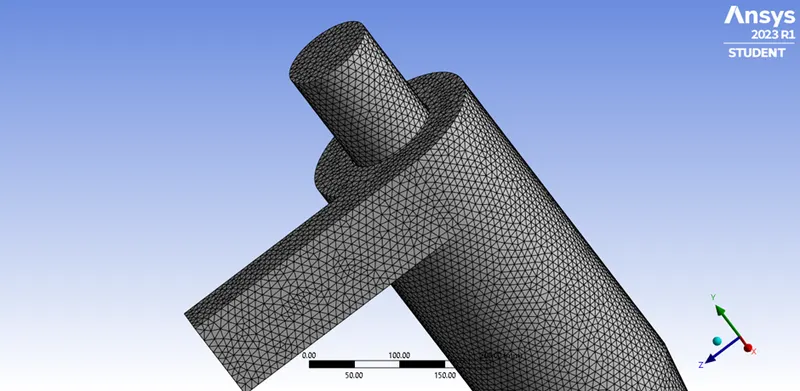
Element Size – 9 mm
No. of Elements – 140987
After meshing the model, choose generate mesh to create the base mesh. However, since mesh refinement affects how many particles enter the inlet, it is preferable to refine the mesh suitably.
The tool for picking faces is chosen. Names are given to the inlets, outlet 1, and outlet 2. The intake is where the particles enter; the top allows the smaller impurities to leave, while the bottom traps the larger ones.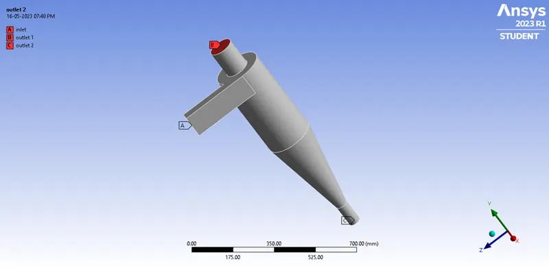
Fluent Setup –
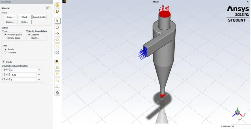
The cyclone separator's orientation is the subject of this analysis. The acceleration caused by gravity needs to be activated, just as it is in the x-y plane. The g value is given as -9.81 in the positive y axis since gravity's acceleration acts upward.
It uses a pressure-based solution. The velocity concept used in the steady state analysis is absolute and normal to the boundary.
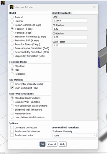
The K-epsilon(2 equation) model with RNG and swirl dominated flow is selected. The wall functions are standard wall functions.
Since temperature is not involved, the Energy is not turned on.
Discrete Phase Modelling –
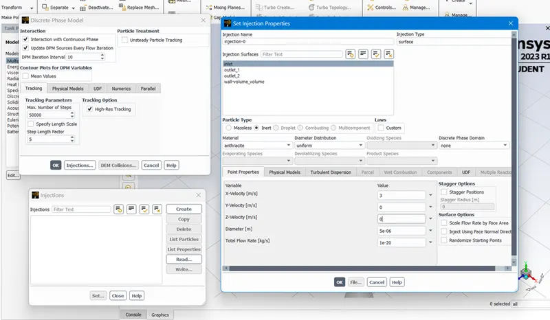
The continuous phase can be interacted with by the model. DPM level of interval is 10.
The sort of particle is inert for injection. Anthracite is chosen from the fluent database. It is emitted from the intake at a speed of 3 m/s in the x direction. This speed can be changed much more. One micrometres is the particle diameter that was selected for the initial analysis. To determine the separation efficiency, the particle diameter is adjusted from one micrometre to five micrometres.
Boundary Conditions –
Three named selections—inlet, outlet 1 top, and outlet 2 bottom—are given the boundary conditions.
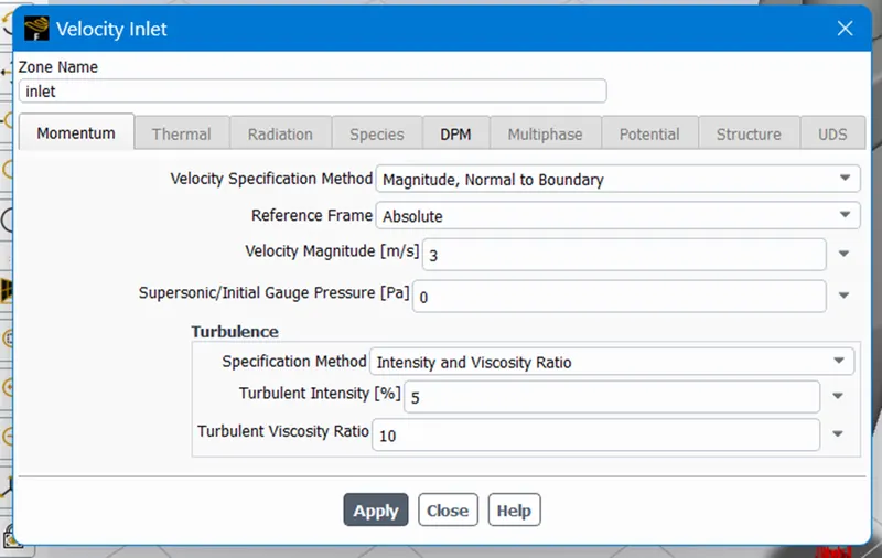
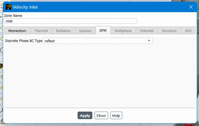
The velocity requirements for inlet are 3 m/s in the x direction, absolute, and normal to the boundary. The DPM state is evident. This means that the particles cannot escape or become stuck in the intake.
Momentum condition for the top outlet is a hydraulic pressure condition, and DPM condition is escape. This Boundary allows for the escape of particles.
Additionally a pressure outlet, the bottom outlet's DPM condition is trap.
Solution Methods –
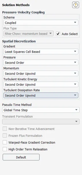
The COUPLED technique is selected for the pressure velocity coupling. The gradient is based on cells with the least squares. Second order upwind for pressure, momentum, turbulent kinetic energy, and turbulent dissipation rate.
Initialization –
Standard initialization is done with flow from inlets.
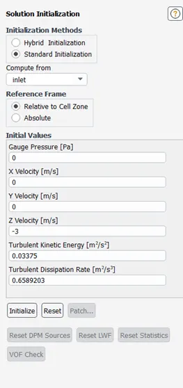
The analysis is done for 225 iterations.
Results-
case(1)
In this case, we are making the velocity constant and we are visualizing the difference in results for different particle size
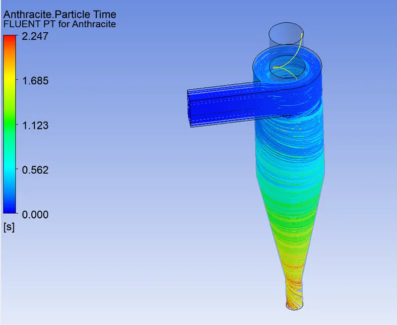
Findings for 1 micron-sized particles travelling at 3 m/s
Pressure at inlet-
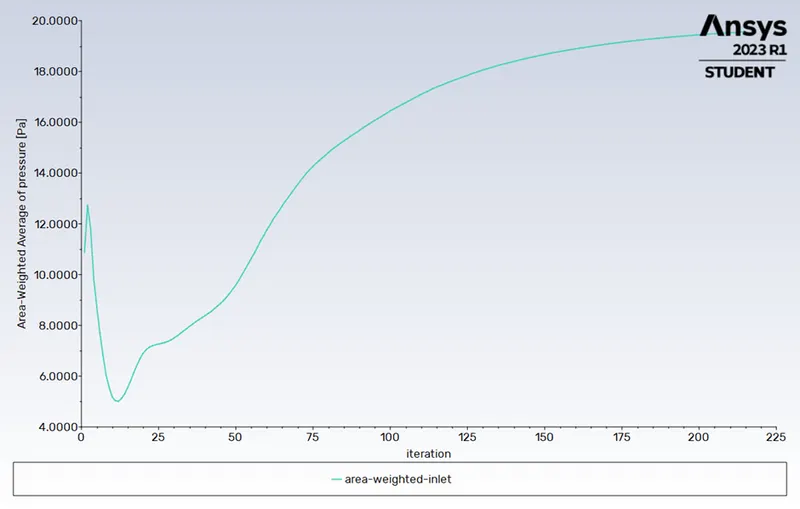
Pressure at outlet-
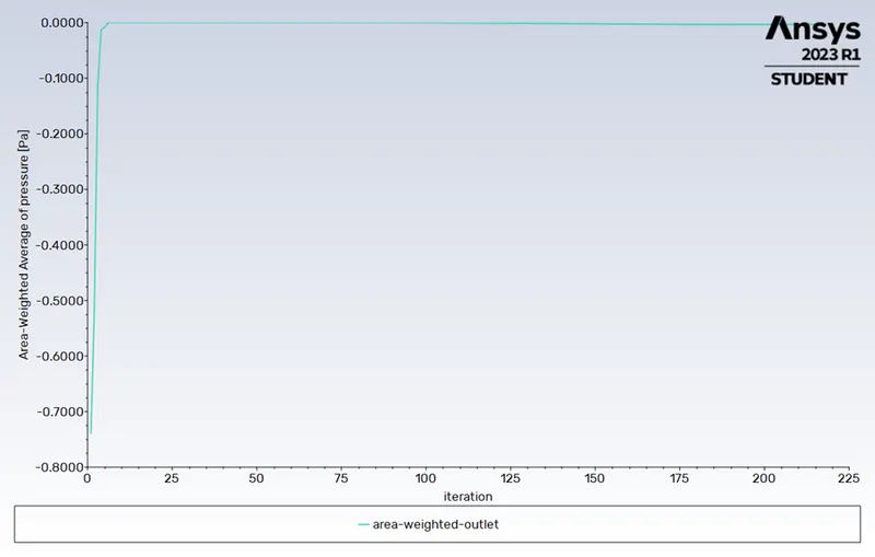
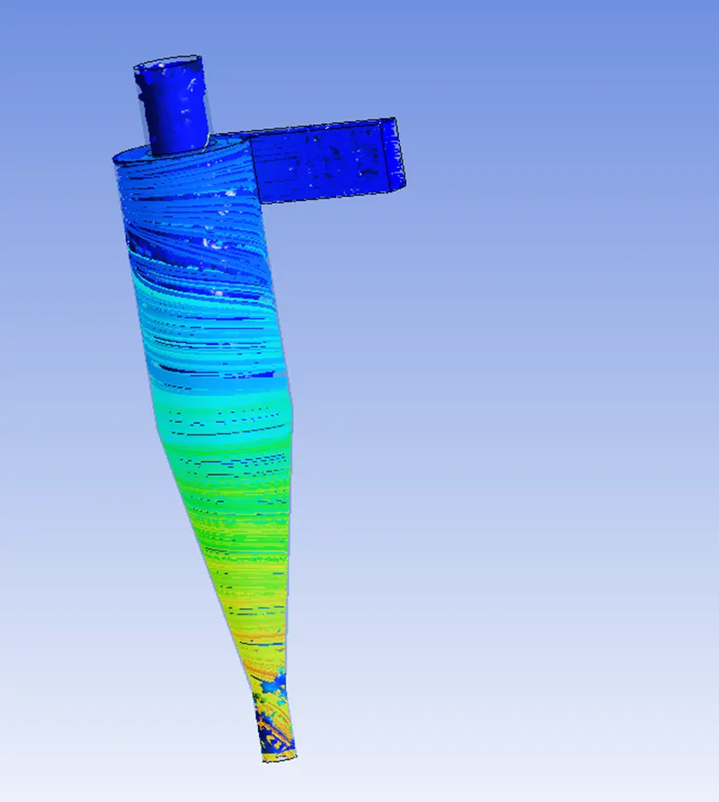
Particle Tracking –

Separation Efficiency in % = No. of Particle Trapped/ No. of Particle Tracked= (52 / 98) * 100
Separation Efficiency = 53.06 %
results for the particle size of 2 micron with a velocity of 3m/s
Pressure at outlet -
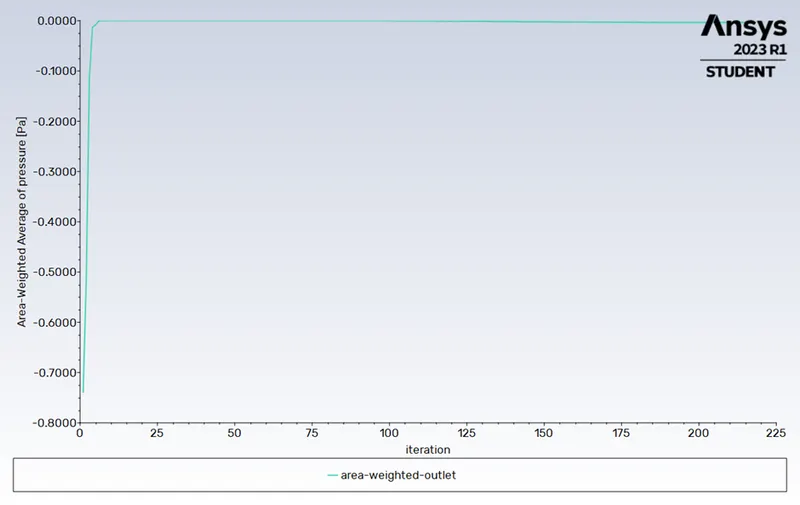
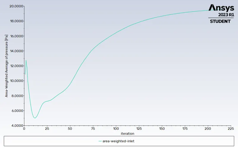
Pressure at inlet -
Residuals Graph -
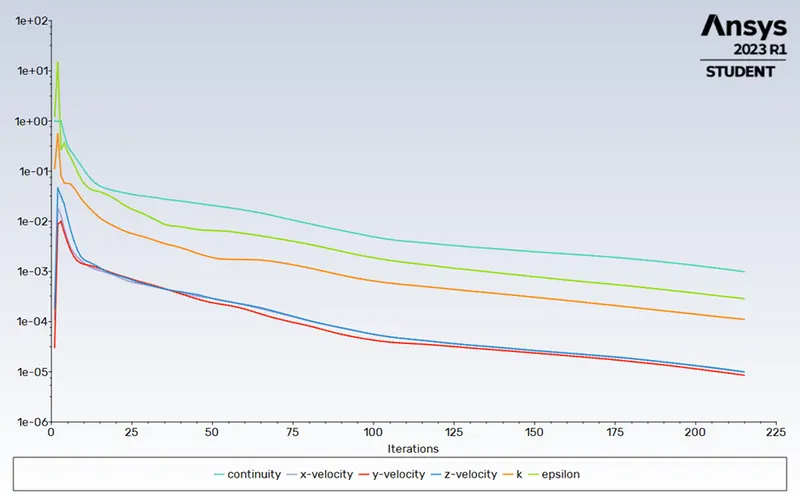
Particle Tracking –

Separation Efficiency in % = No. of Particle Trapped/ No. of Particle Tracked= (75 / 98) * 100
Separation Efficiency = 76.49 %
results for the particle size of 5 micron with a velocity of 3m/s
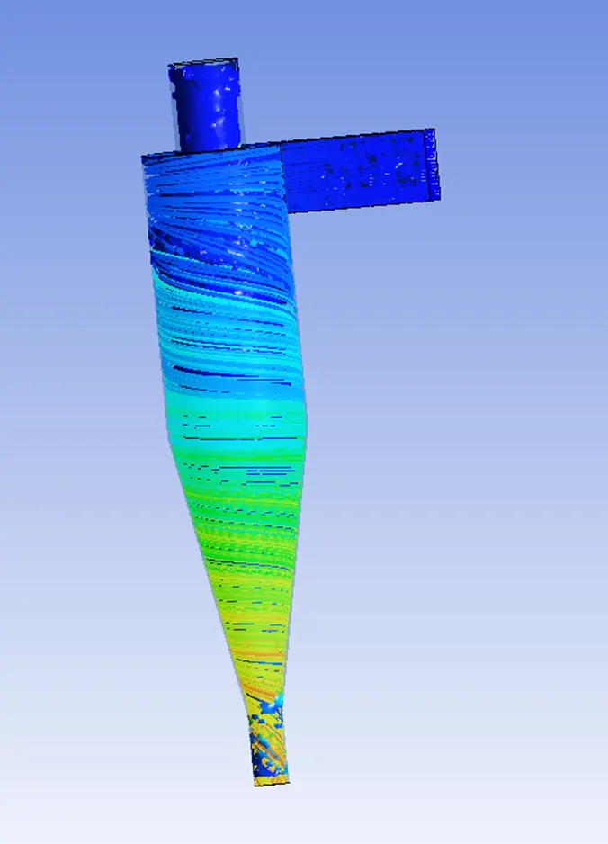
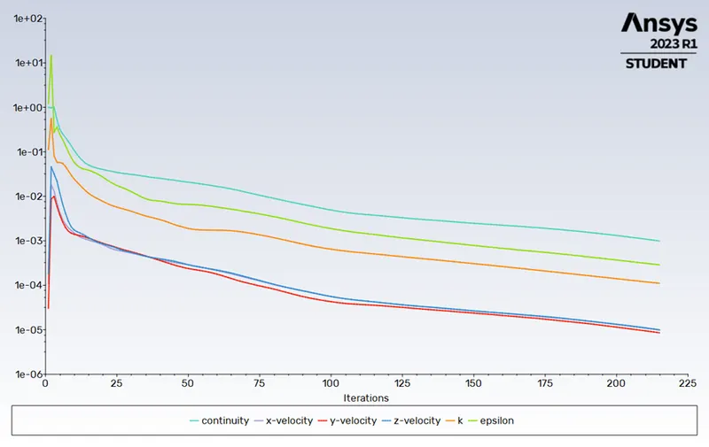
Residuals Graph -
Pressure at inlet -
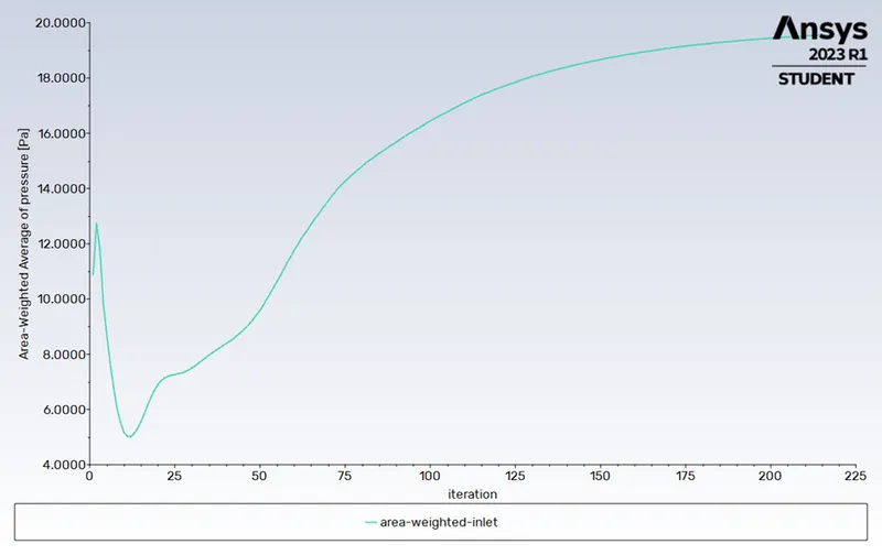
Pressure at Outlet -
Particle Tracking –

Separation Efficiency in % = No. of Particle Trapped/ No. of Particle Tracked= (98 / 98) * 100
Separation Efficiency = 100 %
Case II
Results for the varying velocity and kepping the particle size constant i.e 5 micron
Inlet velocity of the particle and the discrete phase is same i.e 1m/s
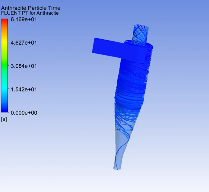
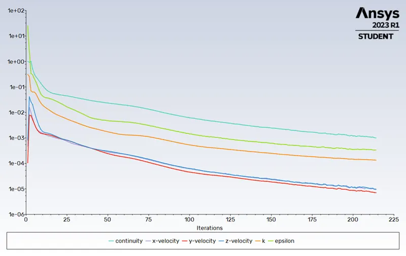
Residuals Graph -
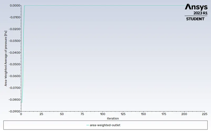
Pressure at outlet -
Pressure at inlet -
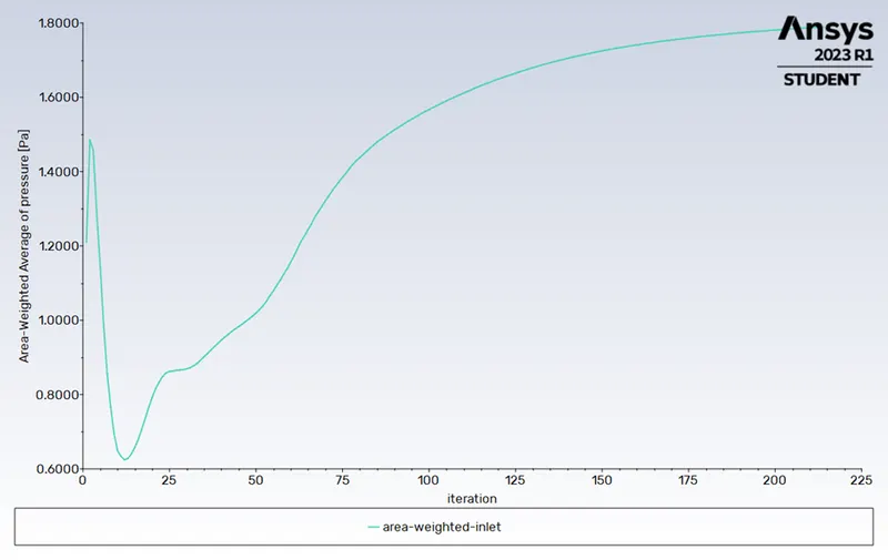
Particle Tracking –

Separation Efficiency in % = No. of Particle Trapped/ No. of Particle Tracked= (7/ 98) * 100
Separation Efficiency = 7.14 %
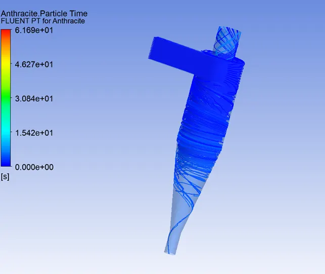
Inlet velocity of the particle and the discrete phase is same i.e 3m/s
Residuals Graph -
Pressure at inlet -
Pressure at outlet -
Particle Tracking –

Separation Efficiency in % = No. of Particle Trapped/ No. of Particle Tracked= (98/ 98) * 100
Separation Efficiency = 100 %
Inlet velocity of the particle and the discrete phase is same i.e 5 m/s
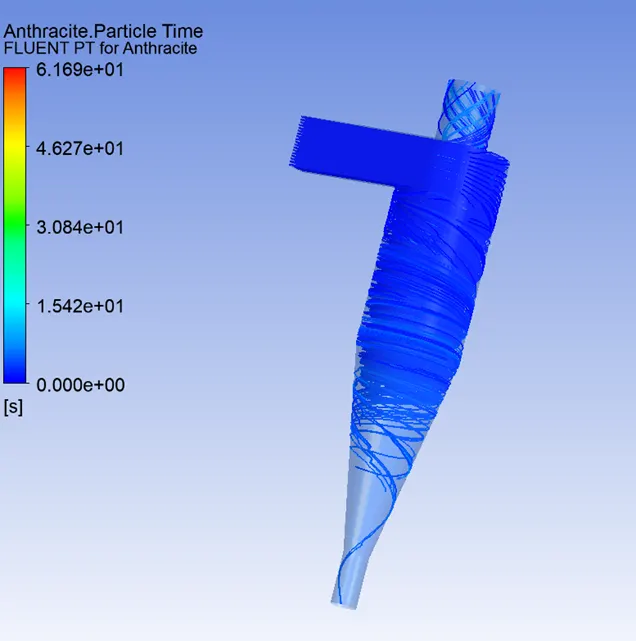
Residuals Graphs –
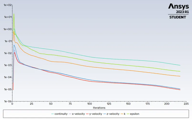
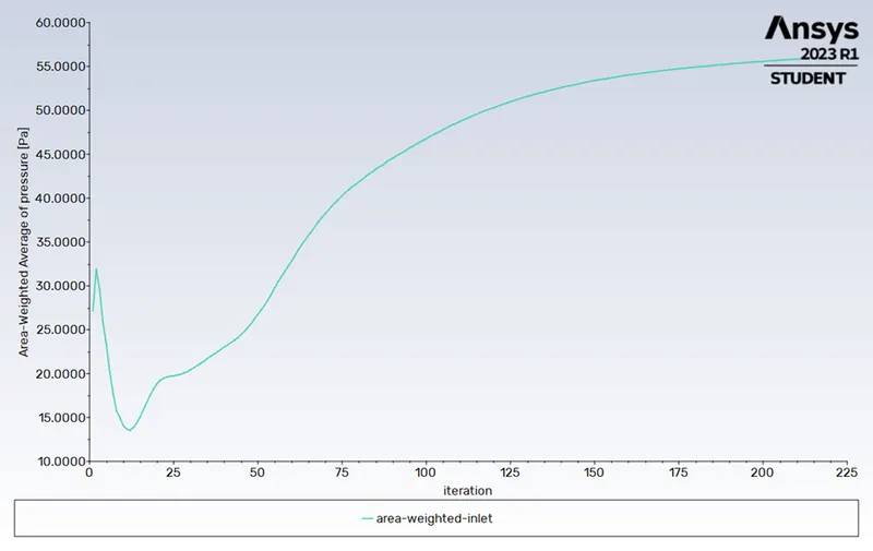
Pressure at inlet –
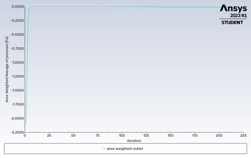
Pressure at outlet -
Particle Tracking –
Separation Efficiency in % = No. of Particle Trapped/ No. of Particle Tracked= (98/ 98) * 100
Separation Efficiency = 100 %
Summary, Conclusion & Result –

If the velocity of the particle is kept constant and increase the particle size, the separation efficiency increases but the pressure almost constant with the same velocity.

If the particle size is kept constant and increase the velocity, the separation efficiency and pressure drop increases.
Separation Efficiency –
It is described as the percentage of particles of a particular size that are collected in the cyclone as opposed to those that enter the cyclone. Experience has shown that raising particle mean diameter and density, increasing gas tangential velocity, decreasing cyclone diameter, increasing cyclone length, and extracting gas and solids simultaneously through the cyclone legs all boost the separation efficiency of cyclone separators.
The separation efficiency in this instance is defined as the ratio of concentration that has been removed from the feed stream to the initial concentration in the feed stream, depending on the particle history data. Ratio of the tracked particle total to the number of captured particles in this scenario.
Separation efficiency = no. of particles trapped / no. of particles tracked
Pressure Drop -
In a cyclone separator, the pressure drop throughout the cyclone is crucial. The performance characteristics of a cyclone are substantially impacted by the pressure decrease. The entry and exit losses, friction, and kinetic energy losses within the cyclone all contribute to the overall pressure reduction in the cyclone. The body often experiences the most pressure reduction as a result of whirling and energy loss.
The difference in total pressure between two places on a fluid-carrying network is known as pressure drop
Pressure drop, ΔP = Total inlet pressure - Total Outlet Pressure (trap & escape)
- To write a few words about any four empirical models used to calculate the cyclone separator efficiency.
1. Iozia and Leith Model
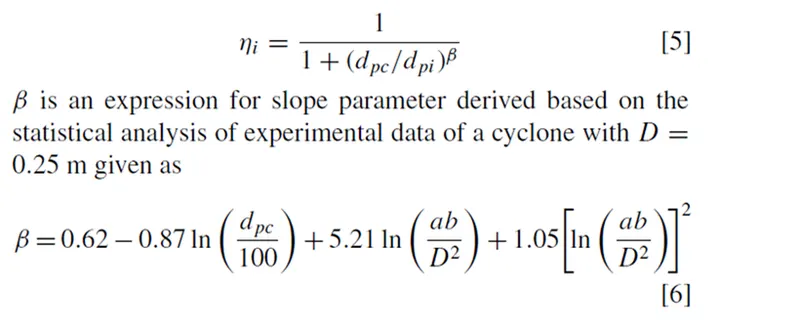
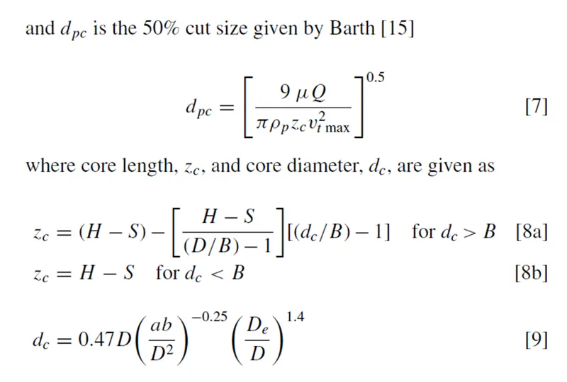
Iozia and Leith logistic model is a modified version of Barth Model, which is developed based on force balance.
The model assumes that a particle carried by the vortex endures the influence of two forces: a centrifugal force, Z and a flow
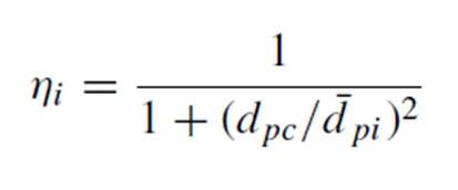
resistance, W. The collection efficiency ηi of particle diameter
d_pi can be calculated from
- Li and Wang Model
Particle bounce or re-entrainment as well as turbulent diffusion near the cyclone wall are both included in the Li and Wang model. It is possible to express the particle distribution in the cyclone analytically in two dimensions. The following presumptions served as the foundation for the Li and Wang model:
- For uncollected particles inside the cyclone, the radial particle velocity and the radial concentration profile are not constant.
- The following boundary conditions are taken into account when considering the turbulent diffusion coefficient and particle bounce re-entrainment on the cyclone wall:
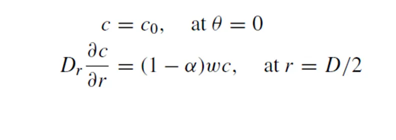
The tangential velocity is related to the radius of cyclone by

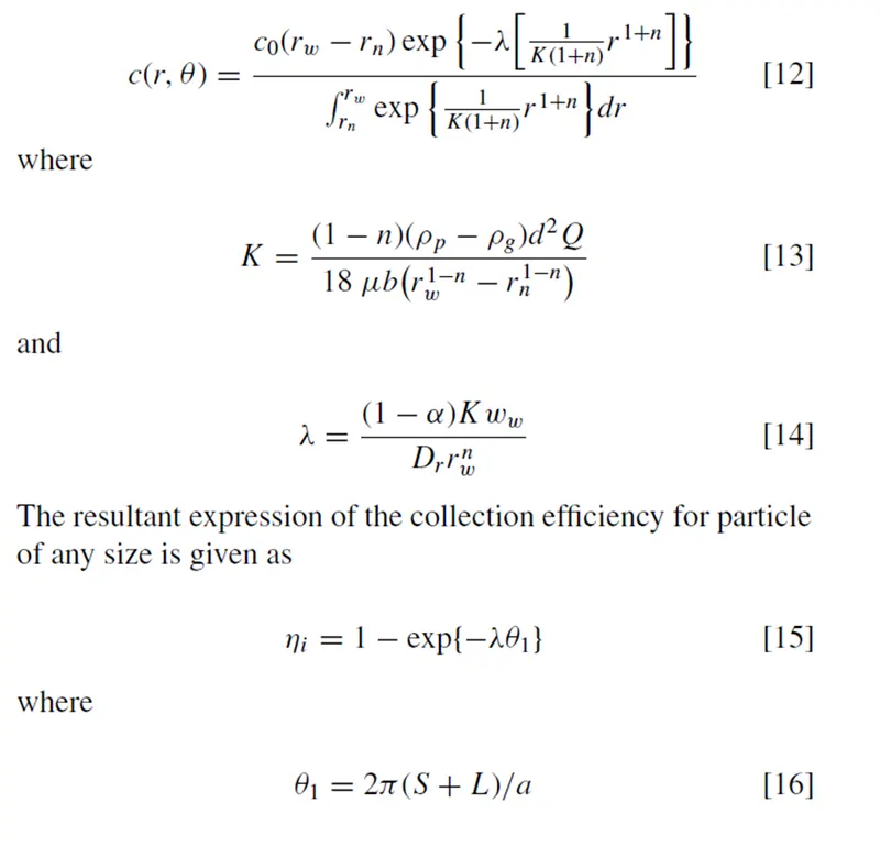
The concentration distribution in a cyclone is given as
- Koch and Licht Model
The Koch and Licht collecting theory recognised the distribution of gas residence periods within the cyclone and the intrinsically turbulent nature of cyclones. Koch and Licht made the following additional assumptions for describing particle motion in the entry and collecting regions:
- There is no slip in the tangential direction between the particle and the gas because the tangential velocity of a particle is equal to the tangential velocity of the gas flow.
The tangential velocity and cyclone radius are connected by:

A force balance and an equation on the particles collection yields the grade efficiency
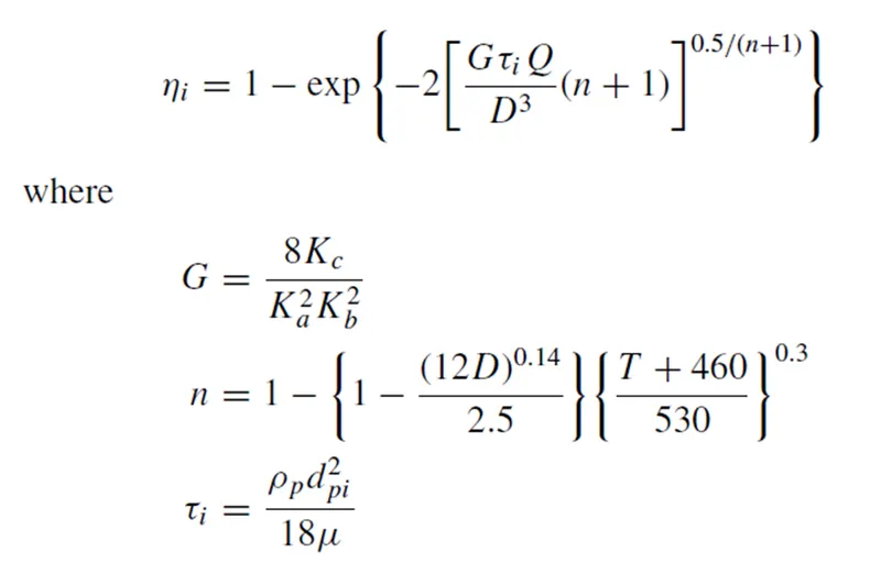
G is a factor related to the configuration of the cyclone, n is related to the vortex and is the relaxation term.
- Lapple Model
Without taking into account flow resistance, the Lapple model was established based on force balance. Lapple made the supposition that a particle entering the cyclone is dispersed uniformly over the inlet hole. In the cyclone, the particle that passes from the half-width entrance to the wall is gathered with a 50% efficiency. Lapple created a semi-empirical relationship to determine a 50% cut diameter, d_pc, and it is,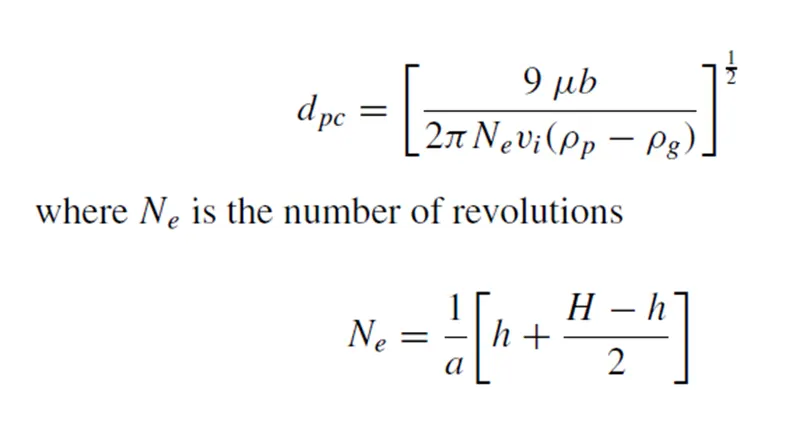
The effectiveness of collecting particles of any size is determined by,