Generation of CFD meshing on Turbocharger
Aim- To generate CFD meshing on the turbocharger
Procedure-
By observing the geometry carefully, we can see that there is so many glitches and geometry errors are present. So, the first task we have to do is the TOPO cleanup.
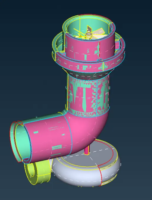
By observing the gitched surfaces we can try delete the non-required sufaces by clicking on the cross hatches with the PID region selector with creating new surfaces with new command in face tab when required.
Also at some surfaces there was very difficult to project surface as it is. So, we create small small surfaces as shown in below picture
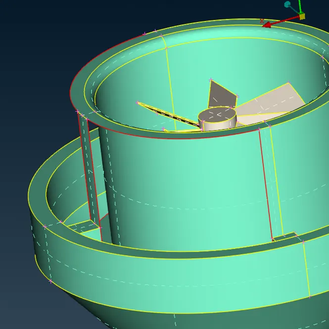
Some single con issues can be used solved by using intersect command in faces tab. As shown in following figure
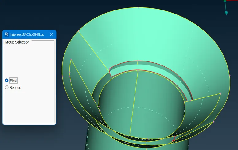
To convert triple cons into single/double cons we can use the release option in cons tab.
and TOPO command in faces tab can be used to do opposite action of the release command.
In the following image, we can observe that there is no surface is present. To create surface in that region we have to create many small-small surfaces.
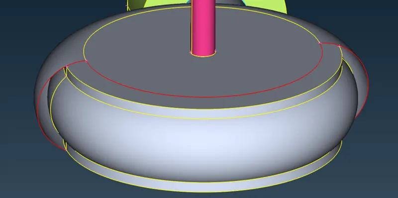
In order to create new surfaces we have to plot different hot points. As shown in below
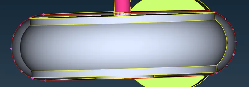
By using new faces command we can create surface as per our requirement
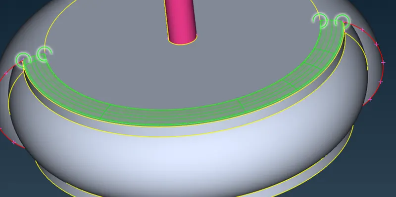
By using the same method we can create no. of surfaces
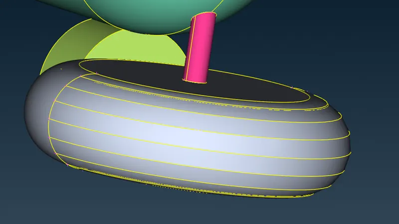
Now the next step is to check again is there any single/triple cons are present in the geometry. In order to check that we should hide all other cons expect the con we are looking for or else we can check from the geometry check box also.
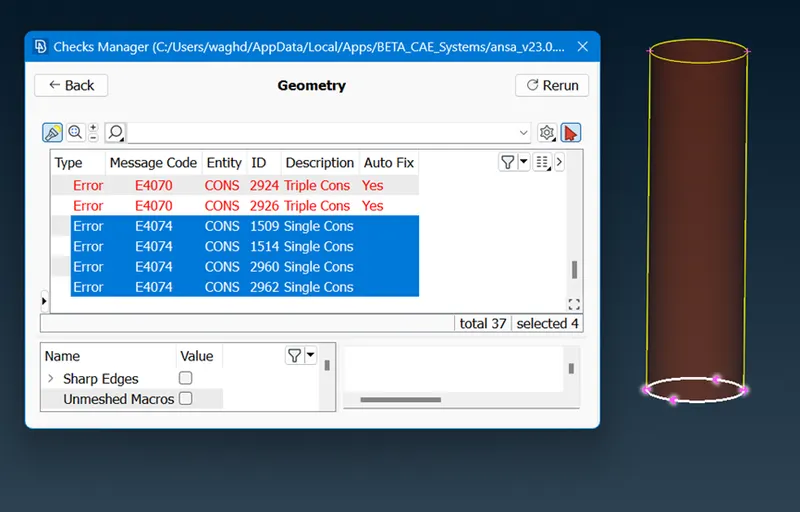
In some cases there are more than one surfaces are overlaped and forming triple cons. This can be solved by deleting extra surface present there. As shown in below
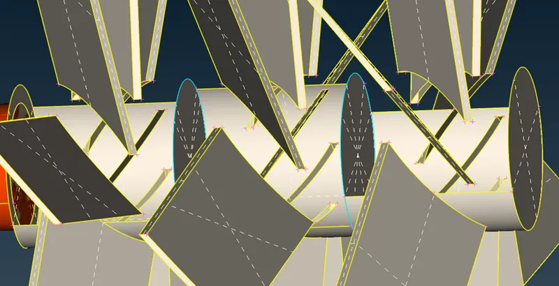
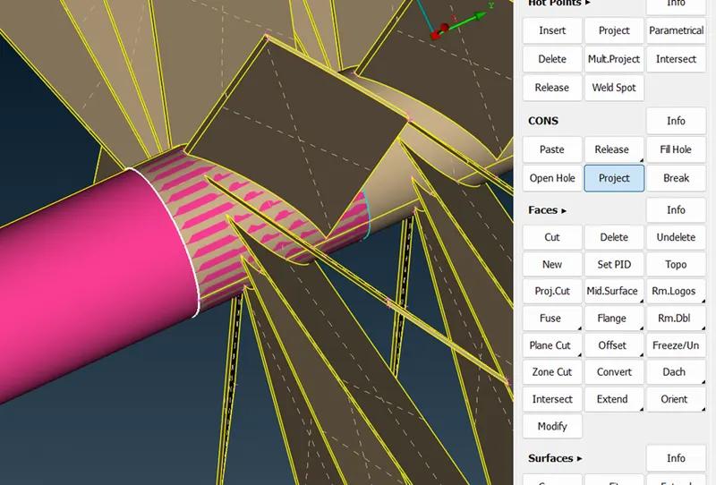
In order to project certain cons on different part of geometry we can use project command in cons tab. Which will project selected entities on certain geometry part.
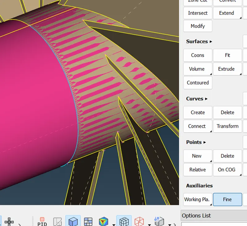
In order to increase resolution we can use fine command in Auxiliaries tab
After solving all single/triple cons, we left with only required triple cons. Now for volumetric meshing we have to close the geometry model opening. In order to do that we have to check the assigned PIDs and close the open surfaces.
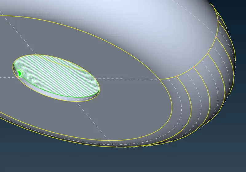
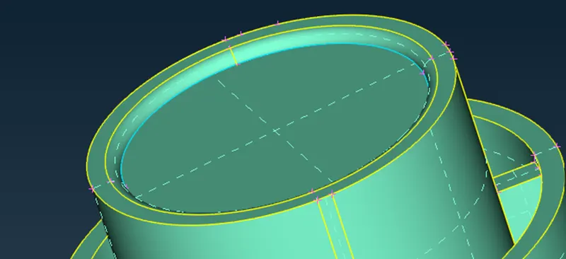
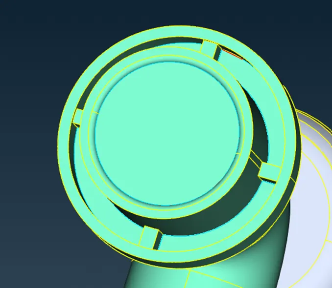
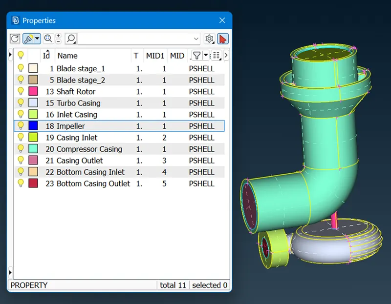
After this process we have to check for any single cons present
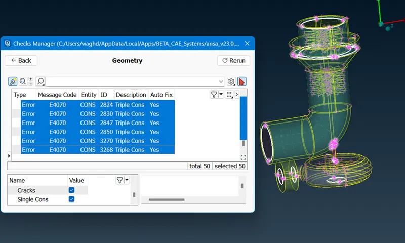
As shown in above figure we do not have any single cons present. Now we are ready to generate mesh. As this is a complex geometry we are not suppose to a single mesh criteria to all components. Instead we are giving different quality criteria to different parts of the geomety.
In the first meshing stage we are meshing compressor casing. The given mesh length for this component is 5mm. That's why in quality criteria we assigned max. & min. length 7 & 3 mm res. and in the mesh parameter the average length is 5mm and minimum length is 3 mm with Tria type of elements.
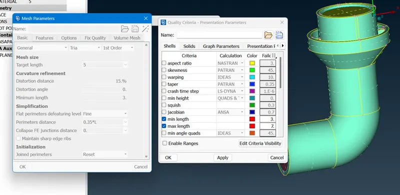
After completing this we are giving mesh paramter and macro size 5 mm each. Then after clicking spot mesh > visible the mesh will generated.
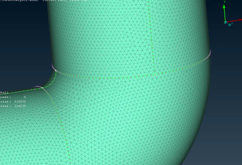
After completing compressor casing mesh. We will mesh Turbo casing and Inlet casing cover toward beacause all of them has a same length given. As the quality criteria and mesh parameters were already given in above part we are ready to give mesh length as 5mm and generate mesh with spot mesh > visible option also in this process we can also add bottom inlet and outlet.
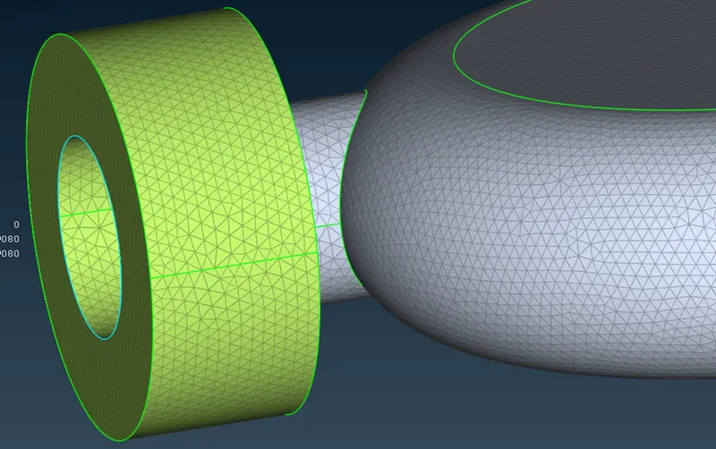
Now, for the meshing of impeller ithe quality criteria should be min. 1 mm and max. 3mm for the targeted 2 mm mesh length and for mesh parameter target length 2mm and minimum length 1mm. Then by giving mesh length perimeters and macros 2 mm we can generate the mesh.
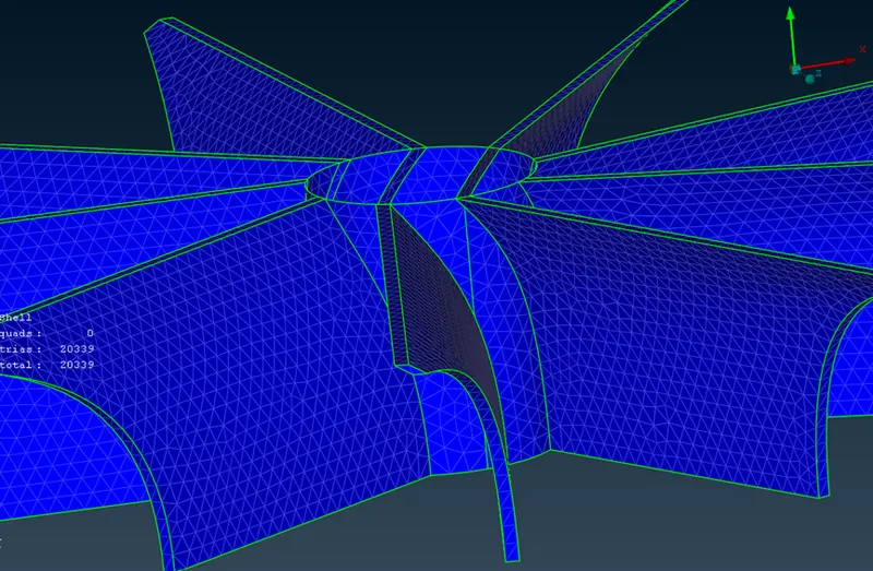
Now for the remaining mesh parts i.e.., Blades and Shaft rotor we can use use quality criteria of min. 0.5mm and max. 2mm. and for mesh parameters target length 1mm and minimum length 0.5mm . After assigning this much we can generate mesh by giving mesh legth parameters and macros 1mm each.
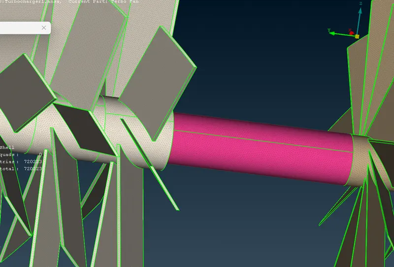
By this method we can mesh all the available components.
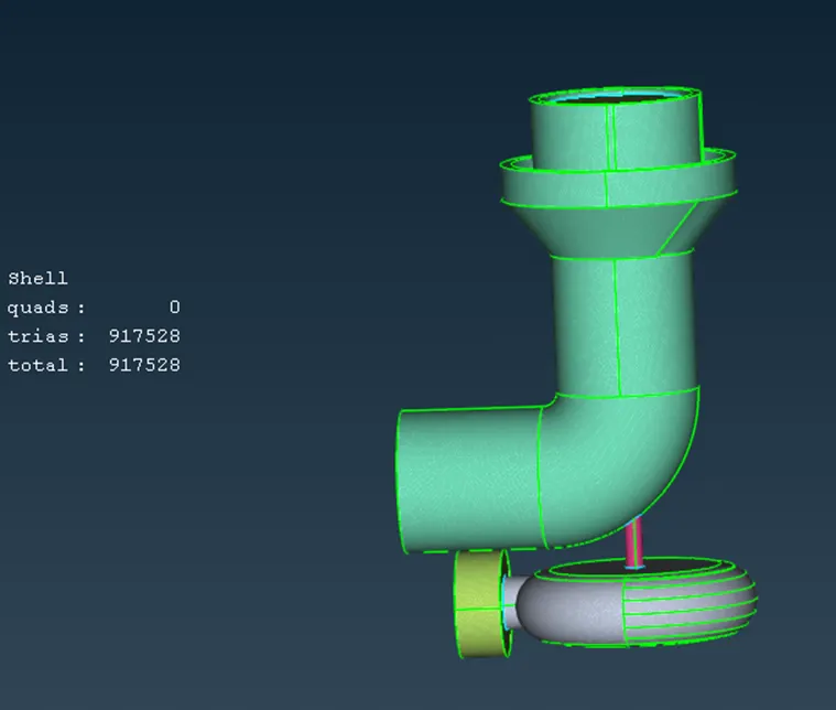
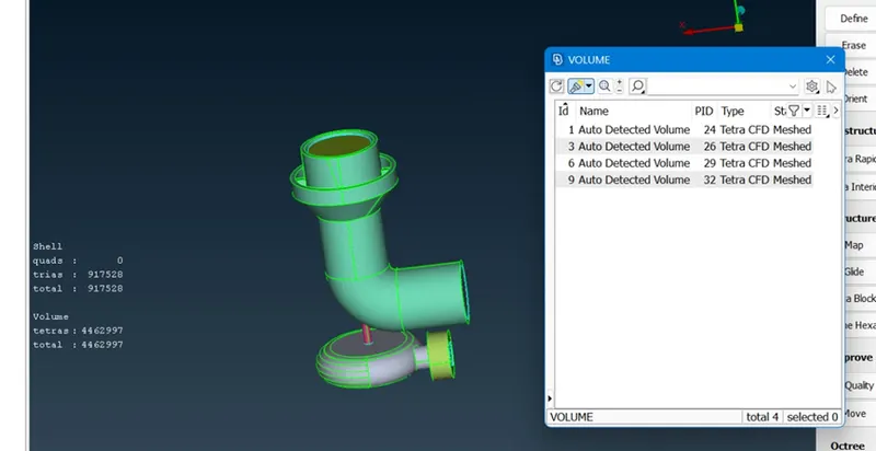
By completing surface mesh we are ready to go with volumetric mesh. In order to do volumetric mesh we should define whole database to the volume.
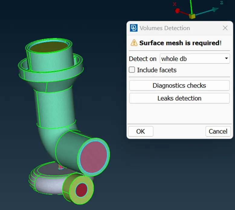
After we need to select and deselect different volumes detected by the ANSA. The unwanted volumes should be deleted.
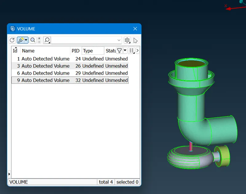
Now it's our task to generate volumetric mesh in the given volumes. We can generate volumetric mesh by right clicking on volume in the list and by selecting Tetra CFD option. By selecting it, it will generate mesh. By following this same procedure we can mesh all the components.
Learning Outcomes-
By performimg this task I get clear Idea of generating volumetric mesh for a certain components by using different tools and commands.
Results-
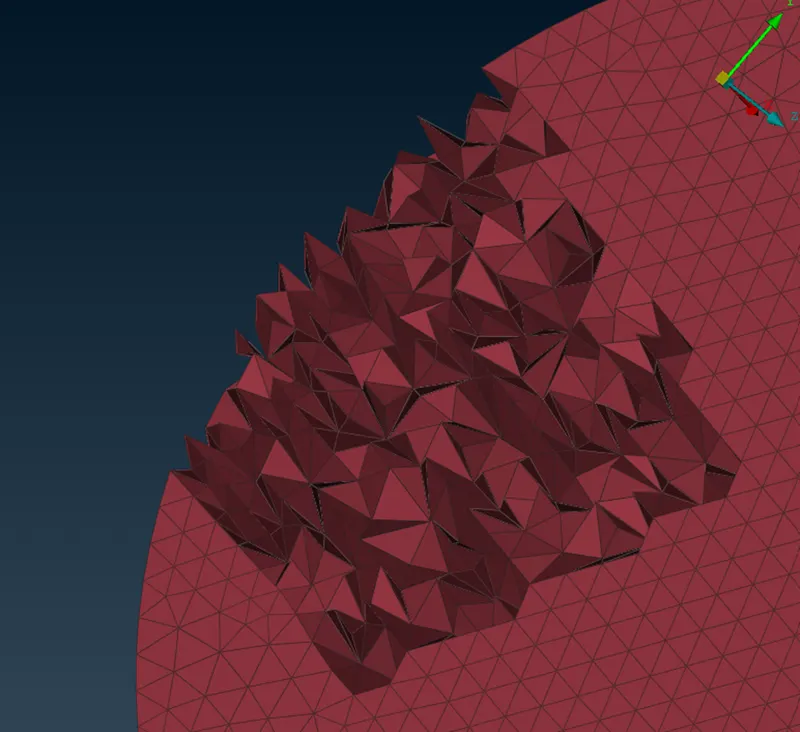
By generating and observing the generated volumetric mesh for a turbocharger we can see that where the smaller mesh size is present there is formation of smaller elements as compare to other mesh size.
Conclusion-
CFD meshing includes surface and Volumetric meshing of components. By generating CFD meshing on turbocharger we can observe different structures of elements present at different locations and also we get some what idea of fluid flow through the given volume.