Surface meshing on a Pressure valve
Aim- To provide surface meshing of pressure vessel of meshing size 1mm, 3mm, 5mm
Procedure- The geometry was provided. But, the geometry has some defects that need to be corrected
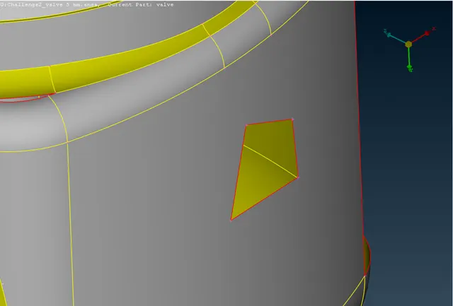
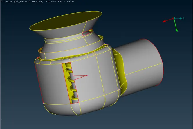
For checking the defects in a given geometry we have to use checks command. In this check command we have to select geometry option. This should be initial step in any geometry analysis. By using this command we can check different defects present in a geometry.
There are so many templates are available in the geometry check function. But for our present application we are using ANSA check template. By selecting ANSA template check we have to select entities that we are wish to check. We are checking following entities as shown in below figure.
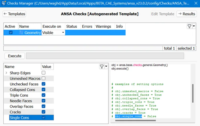
By clicking Execute command we can see different errors present in the geometry
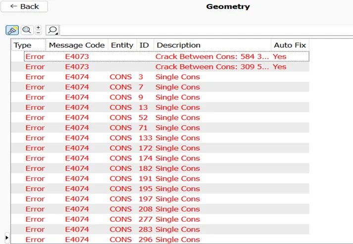
This process of cleaning up geometry errors is called as TOPO clean-up.
As the geometry must not have single cons we have check for single cons by clicking CTRL shift and by turning off double, triple and cross hatches.
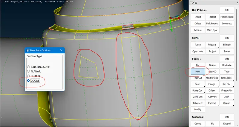
To fill the different holes, present in geometry we can use the new ace option by selecting cons and faces we can fill the geometry with new surface.
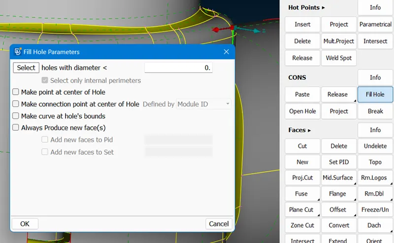
To fill the holes, we can also use the FILL HOLE option in CONS section.
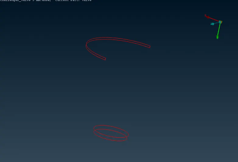
After filling the holes with new face and fill hole command we can check again single cons by clicking ctrl shift
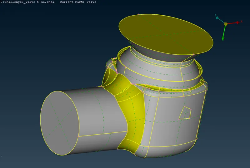
After fixing holes with different methods our looks like below
Now we will check errors with the help of geometry check command.
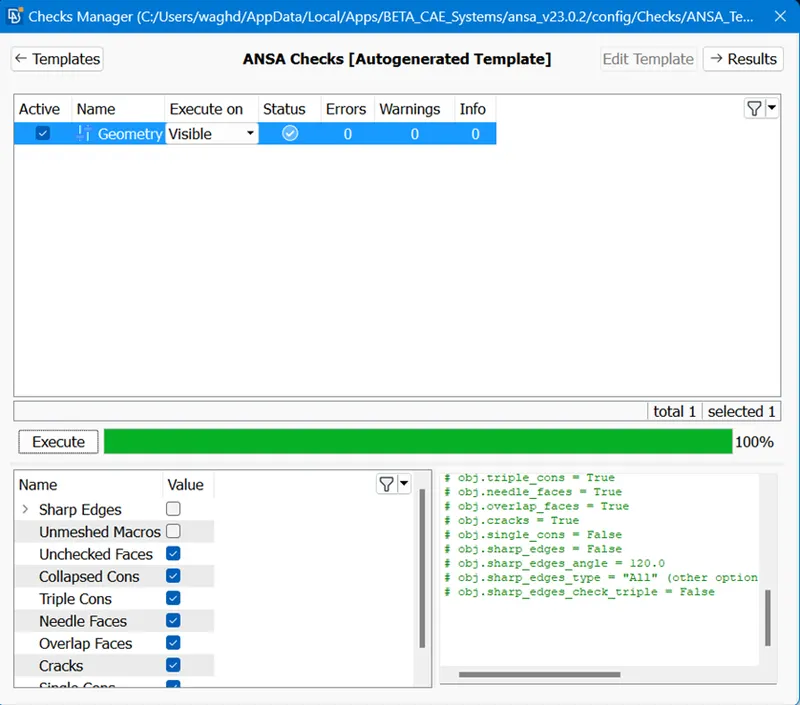
As we found no errors in the geometry check we are ready to proceed further. For doing volumetric mesh the component should be closed from all side to ensure that we close the component with the help of new faces command.
There are so many small surfaces are present in the geometry which will be the restriction for meshing size, To remove such surfaces we are using cut face tool to remove the close lines.
By checking the PID Manager, we get to know that there is only one PID is present, In order to create a new PID we have to right click on PID manager and then select new-PSHELL-PSHELL. By following this steps we create this much of PID’s as shown in below
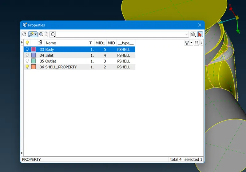
Now we must assign PID to different parts of the geometry by using apply option. By assigning PID properly we can see our geometry as follow
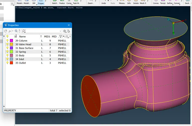
Now we are ready to go for meshing process
Case i. Mesh length 5mm
Select parameters and macros and give mesh length 5mm
Mesh parameters give element type tria and target length 5mm
And then in quality criteria give max. length 7 and min. length 3
Then generate mesh.
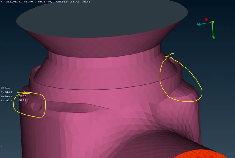
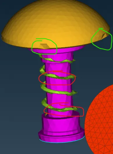
As you can see in the above picture due to the higher mesh size the geometry is not defined properly. In the small areas there is irregular geometry formation is there.
Case ii. Mesh length 3mm
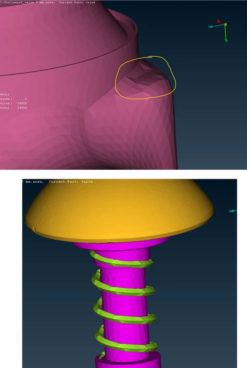
In this mesh length we can see that the is little bit more defined as compared to previous one. Also no. of nodes and elements are also increased.
Case iii. Mesh Length 1mm
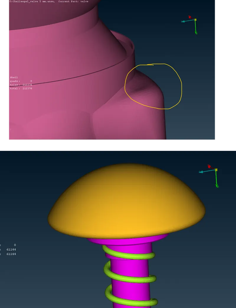
As in this case the component is fined meshed and the geometry is well defined. This type of meshing will lead to better results.
Learning Outcomes :-
By performing this I understood the topo clean-up procedure and importance of different mesh sizes.
Result:-
By generating meshing of different sizes the fine meshing proof to be better meshing length i.e.1mm because in this case the geometry was well defined which leads to the better results of the analysis.
Conclusion :-
Meshing of different sizes leads to different results. Our aim of this task was to analyse the better meshing size. By undergoing different meshing sizes we can conclude that the fine meshing is the better option for doing any surface meshing but also it require more time and more hardware capability.