Week 8 - Simulating Cyclone separator with Discrete Phase Modelling
Aim:- To perform analysis on cyclone separator and calculate the separation efficiency and pressure drop.
Objective:-
- To write a few words about any four empirical models used to calculate the cyclone separator efficiency.
- To perform an analysis on a given cyclone separator model by varying the particle diameter from 1 μm to 5 μm and calculate the separation efficiency in each case. Discuss the results. [Use both the velocity's as 3m/sec.]
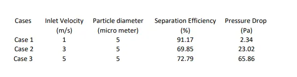
- To perform an analysis on a given cyclone separator model by varying the particle velocity from 1 m/sec to 5 m/sec and calculate the separation efficiency and pressure drop in each case. Discuss the results. [Use particle diameter size as 5 μm for all cases & keep flow velocity same as particle velocity]
Introduction :-
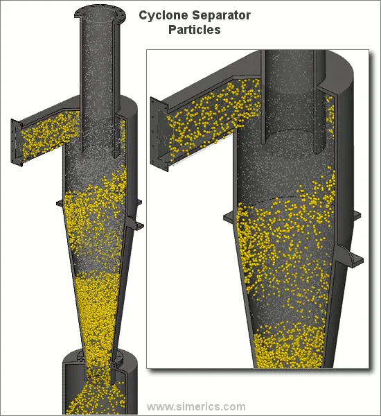
Cyclone separator:The cyclone separator is a common separation and classification equipment, which uses the principle of centrifugal sedimentation. When the mixed liquid to be separated enters the cyclone tangentially from the periphery of the cyclone at a certain pressure, a strong three-dimensional elliptical strong rotating shear turbulence is generated.
Types of cyclone separator :- There are two main designs of cyclone separator, these are the gas cyclone and hydrocyclone. Gas cyclones are used to remove entrained particles from a gas stream. Hydrocyclones are used for separating fluids of different densities.
You can see here, how cyclone separator is separating the dirst particles feom gas streams .
Tracking Parameters:
Tracking Parameters contains parameters that control the tracking of particle trajectories. One simple rule of thumb to follow when setting the two parameters below is that if you want the particles to advance through a domain of length $D$, the Length Scale times the number of Max. Number of Steps should be approximately equal to D.
particle trajectory evaluated in DPM?
In discrete phase modeling, particle trajectory is calculated by integrating the particle force balance equation
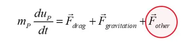
Other forces acting on the particulate matter can include Buoyancy Force, Thermophoretic Force, Brownian Force and Saffman's Lift Force.
Modelling and problem solving approach:
- First import the geometry in spaceclaim
- Extract the fluid volume and supress the solid volume
- Meshing - baseline and refinement and named selection
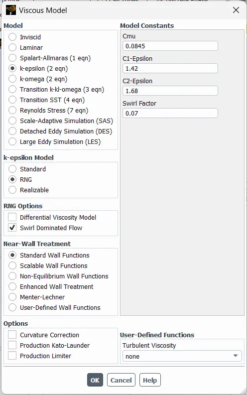
- Steady state simulation using viscous K epsilon (RNG) model
- DPM enabled - Surface Injection ( Particle diameter and velocity)
- Creating materials
- Boundary condition (Velocity Inlet , DPM-reflect)
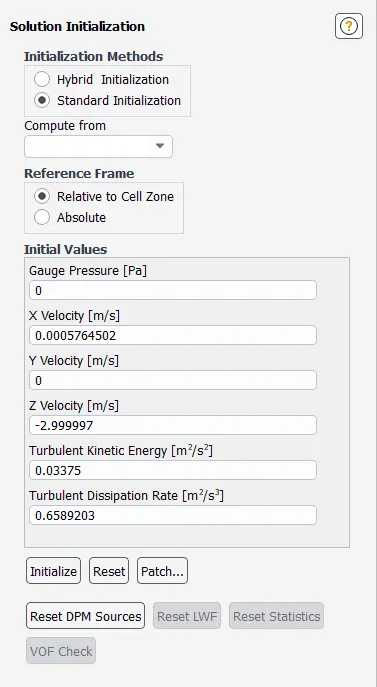
- Standard initializing (Compute from inlet)
- Run Fluent solver
- Post-processign and animation plots
Importing the object in spaceclaim :-
As the object is already given , just need to import the object in spaceclaim and extract the fluid volume and suppress the solid volume as solid volume is not needednhere.
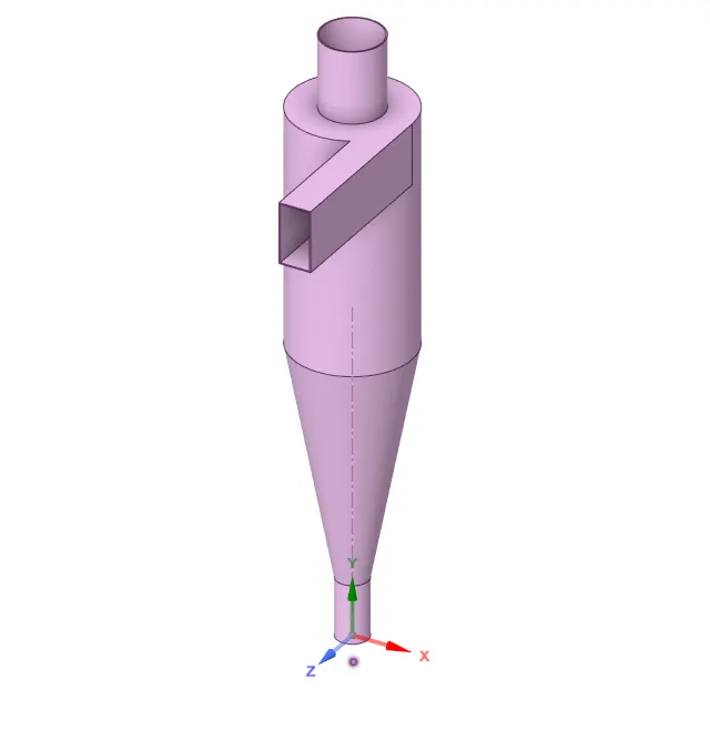
Volume extracted:
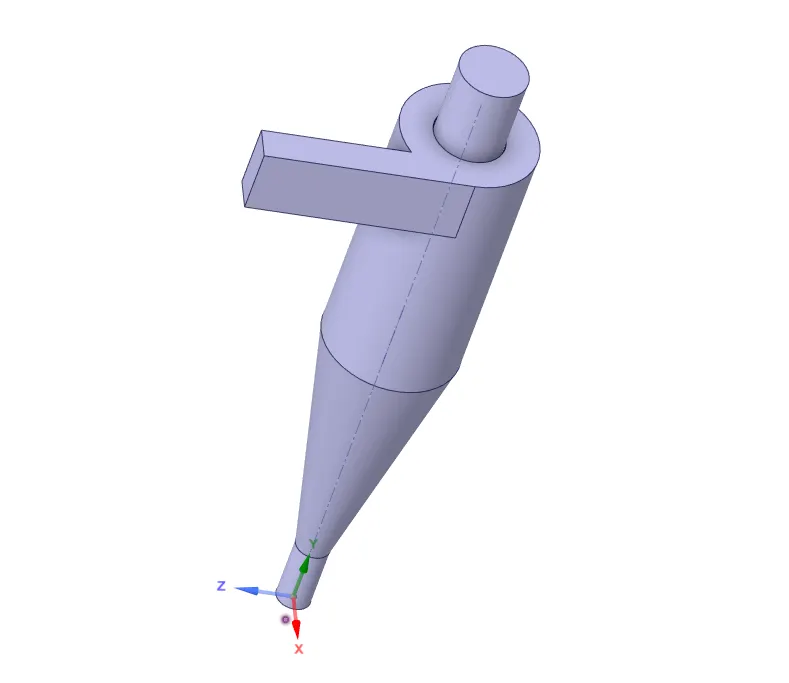
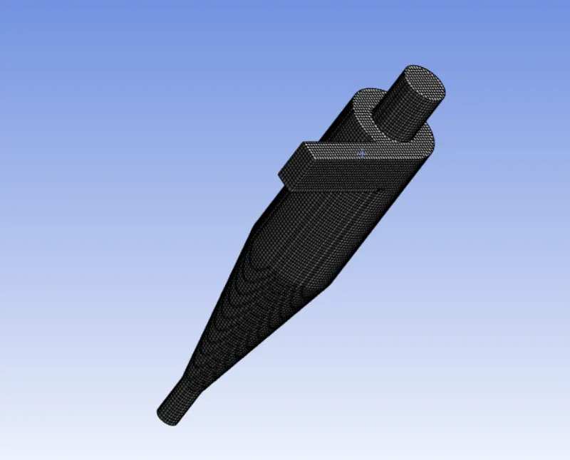
Baseline mesh:
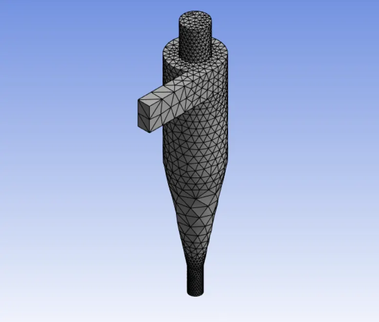
Refined mesh:
- Now we will run a baseline mesh having default size . We go to mesh size and put the desired value>> click on generate mesh tab.
- Now on the next step we will refine the mesh size by 10 mm
For each case we have used same mesh size . We have changed the velocity and particles diameter in order to observe the change in result .
Pre processing set-up:-
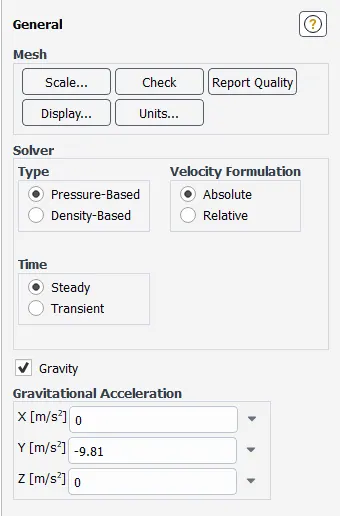
Pressure Based Transient State simulation
Gravity with -9.81m/s^2 in y-axis was enabled
K -epsilon RNG model is used here as it will give more accurate result in our case .
DPM enabled - Surface Injection ( Particle diameter and velocity)
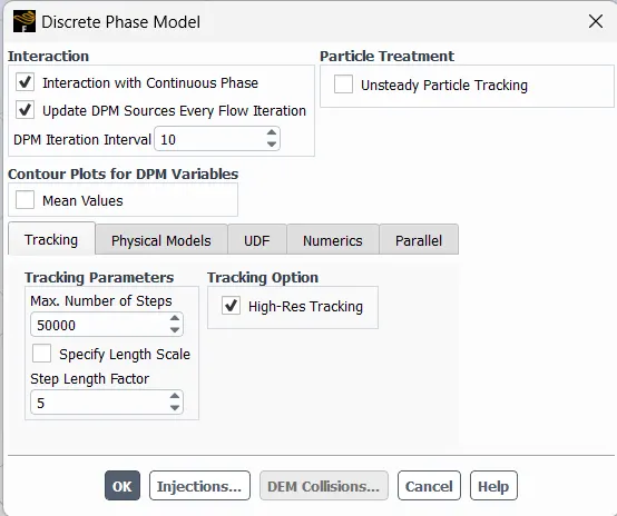
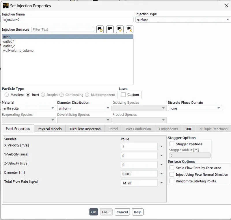
Case 1 ( Inlet velocity = 3 m/s , Particles diameter = 1 micro meter ):
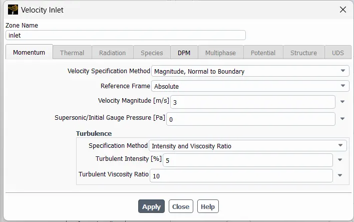
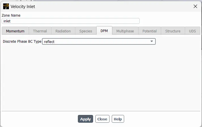
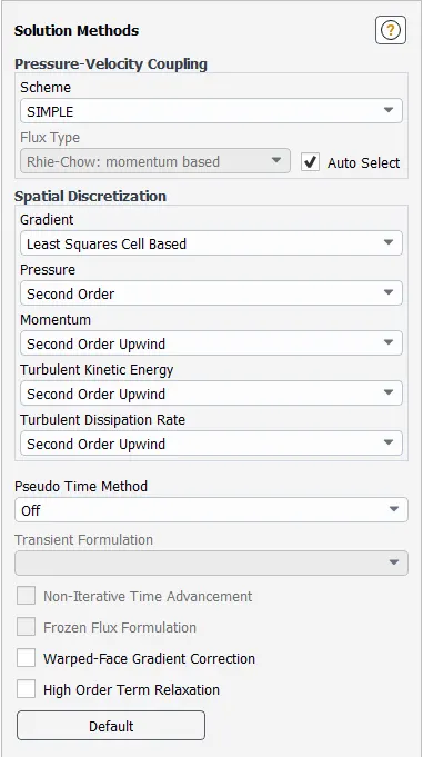
Solution methods:
Solution initialization:
Solution:
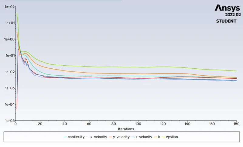
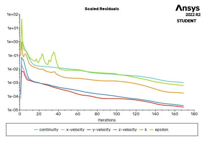
Scaled residuals:
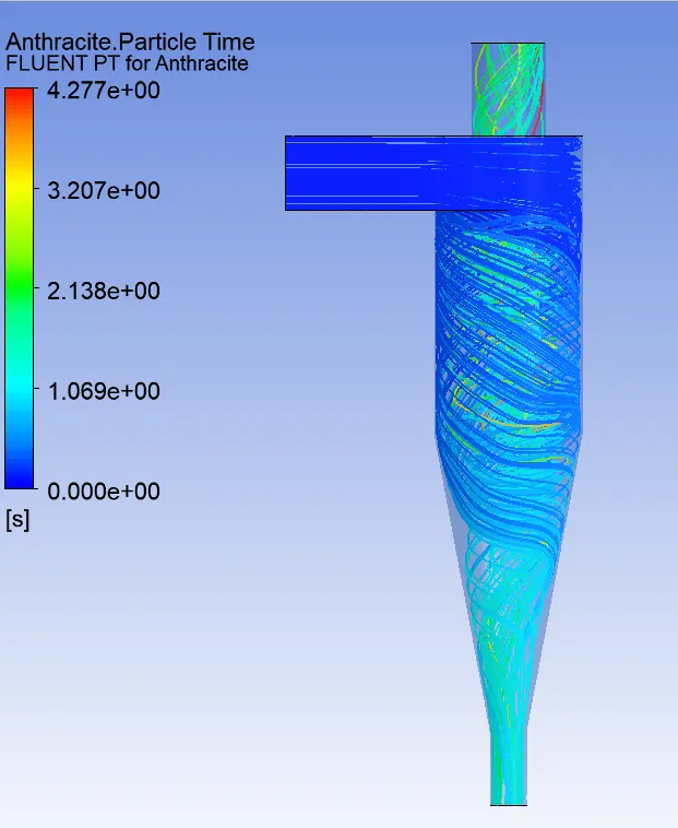
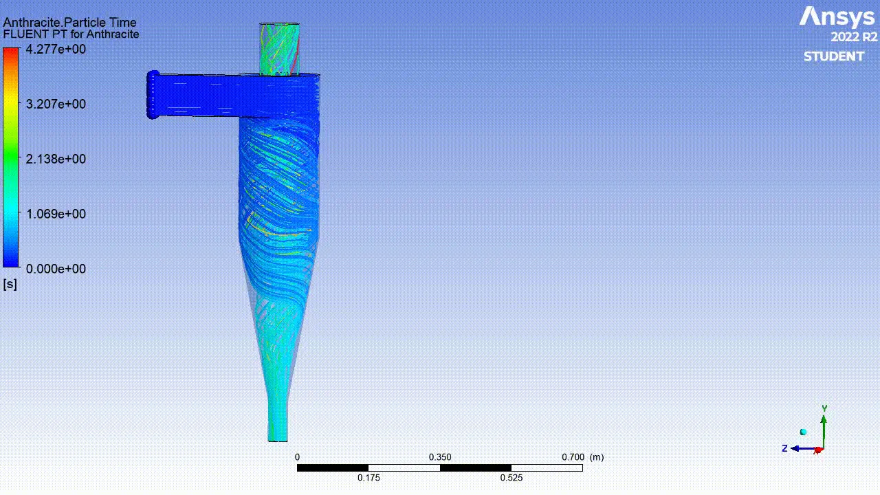
Anthrasite particle flow:
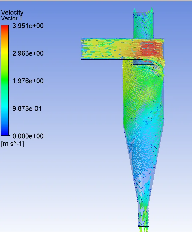
Velocity vector:
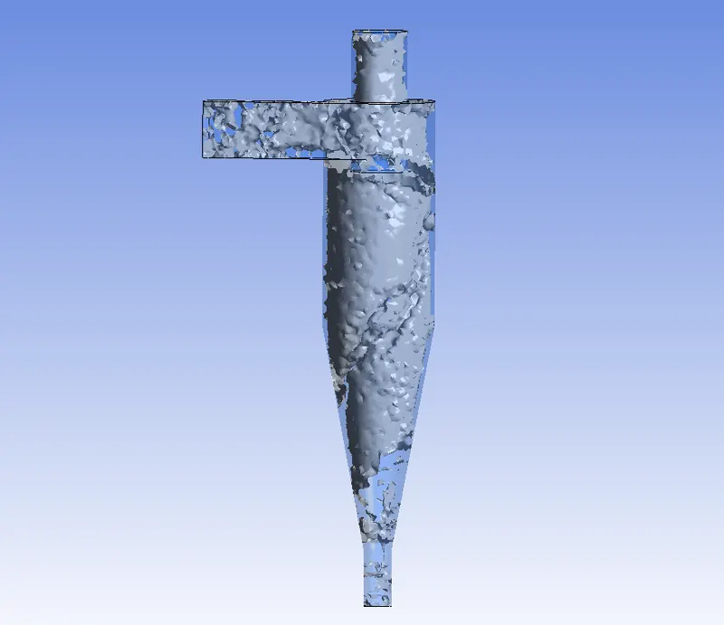
Vortex:
Animation of anthrasite particle flow:
Case 2 ( Inlet velocity = 3 m/s , Particles diameter = 3 micro meter ):
Residual plot:
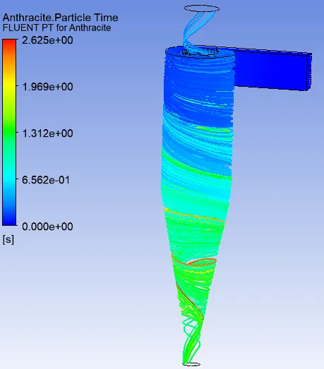
Anthrasite particle flow:
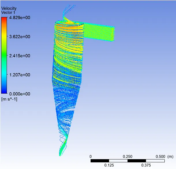
Velocity vector:
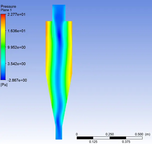
Pressure contour at yz plane:
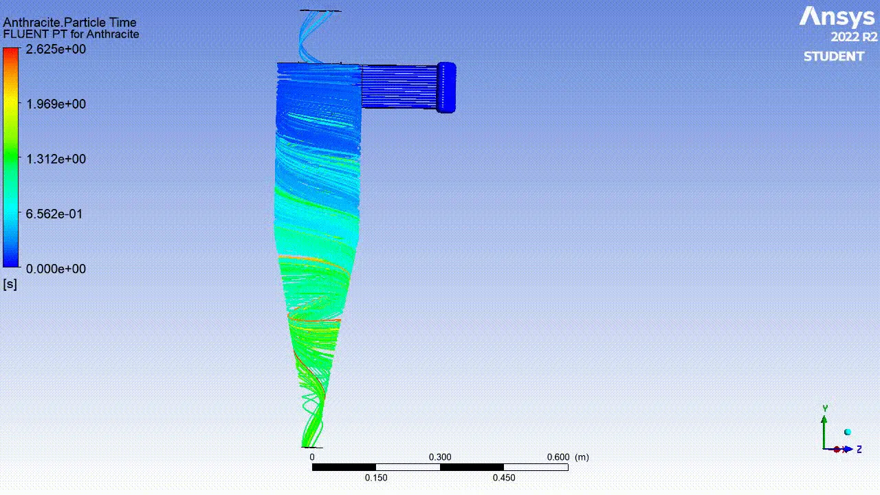
Animation of anthrasite particle flow:
Case 3 ( Inlet velocity = 3 m/s , Particles diameter = 5 micro meter):
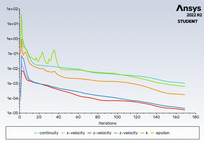
Residual plot:
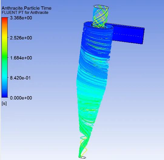
Anthrasite particle flow:
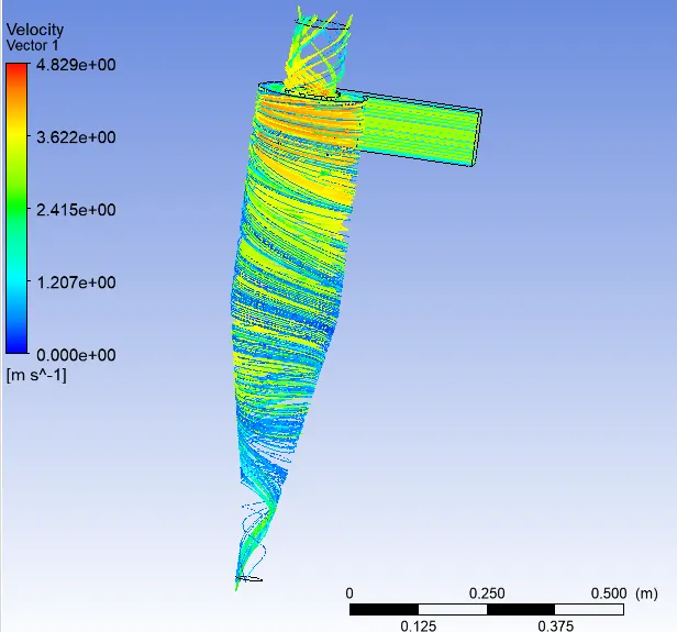
Velocity vector:
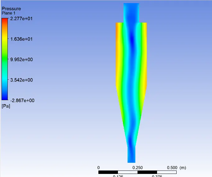
Pressure contour at yz plane:
Animation of anthrasite particle flow:
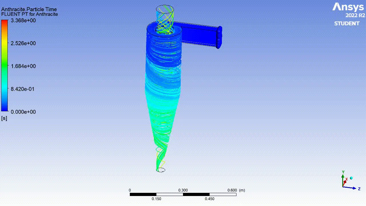
Case 4 (Inlet velocity = 1 m/s , Particles diameter = 5 micro meter):
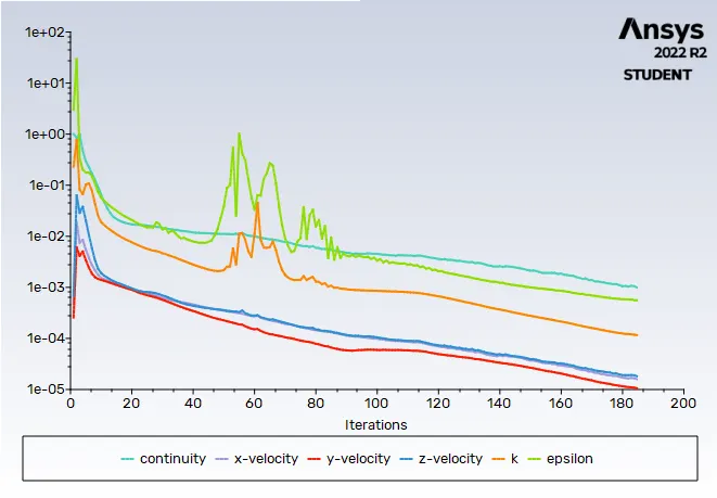
Residual plot:
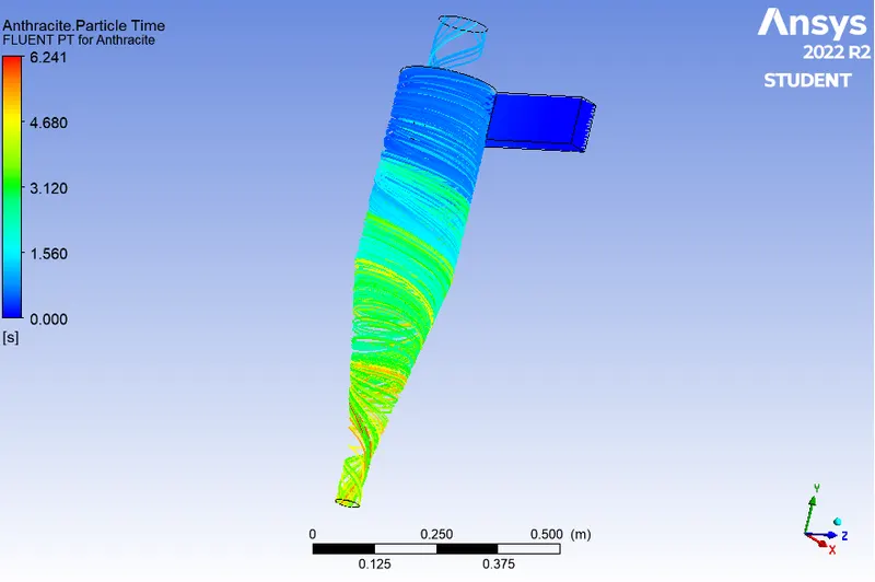
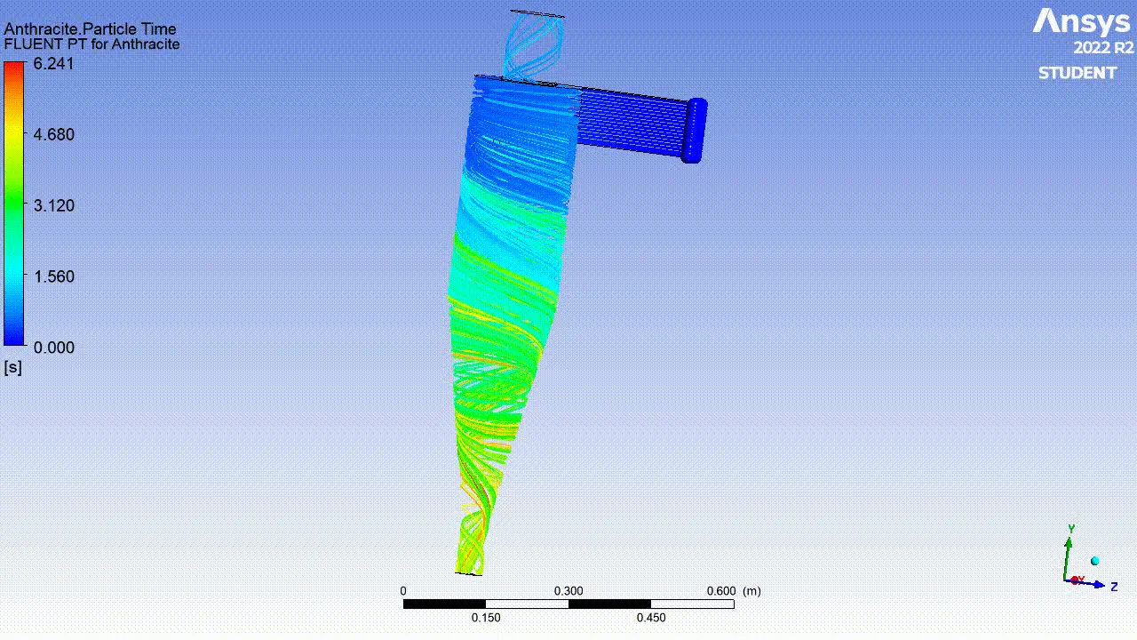
Anthrasite particle flow:
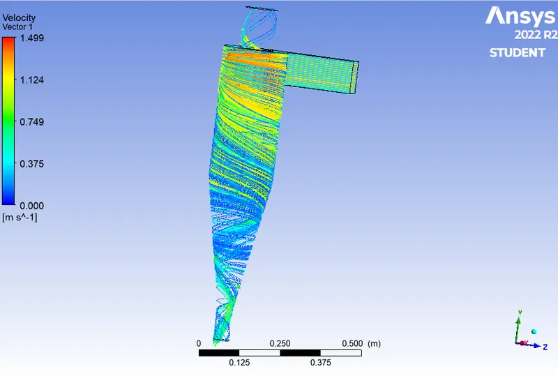
Velocity vector:
Pressure contour at yz plane:
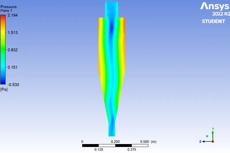
Animation of anthrasite particle flow :
Case 5 (Inlet velocity = 5 m/s , Particles diameter = 5 micro meter):
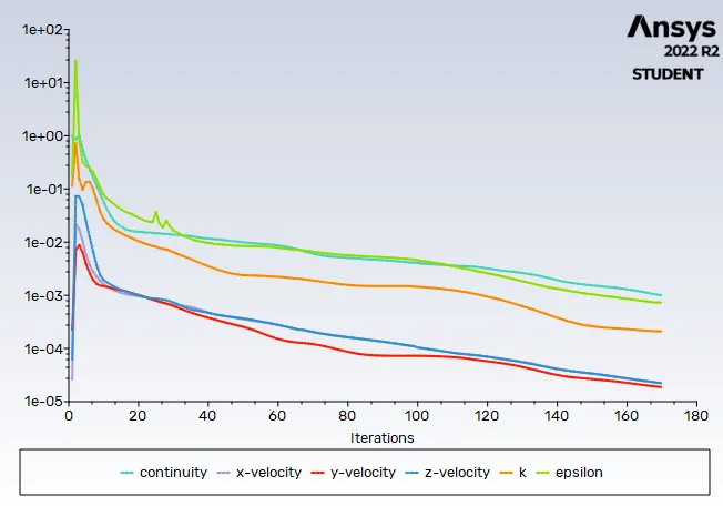
Residual plot:
Anthrasite particle flow:
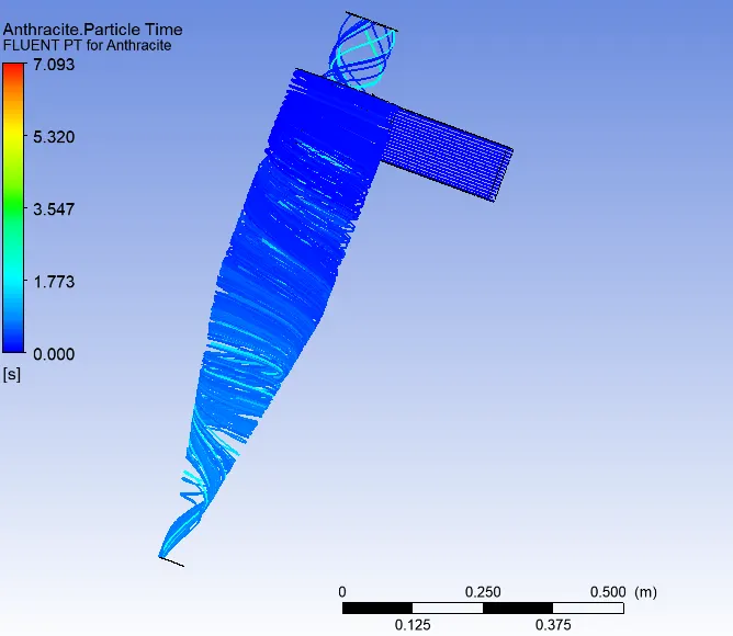
Velocity vector:
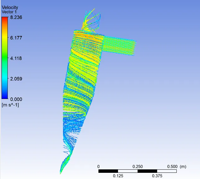
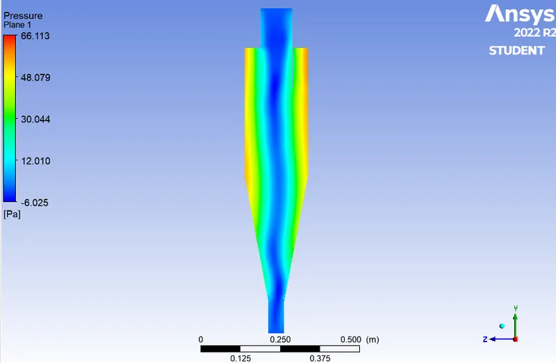
Pressure contour at yz plane:
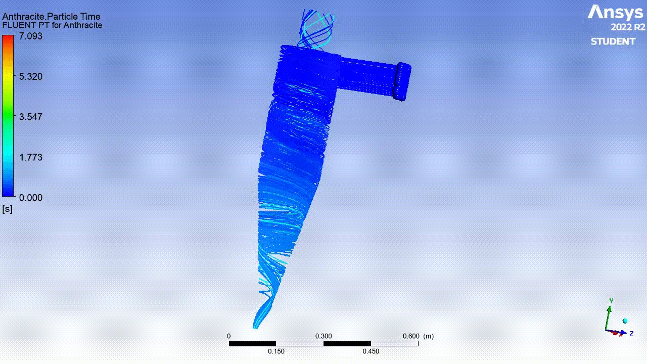
Animation of anthrasite particle flow:
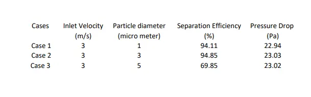
Result:
- The change in separotor efficiency and pressure drop whie changing the Particles diameter from 1 to 5 micro meter by keeping the inlet velocity constant as 3 m/s.
- To see the difference in result we have changed the velocity from 1 to 5 m/s by keeping particles diameter constant as 5 micro meter.
Conclusion:
- From this result that pressure drop is incresing with increasing of particles diameter.
- While increasing the velocity the pressure drop is increasing.
References :
https://www.sciencedirect.com/science/article/pii/S0307904X06000291
https://www.researchgate.net/publication/232747389_A_CFD_Study_on_the_Prediction_of_Cyclone_Collection_Efficiency