Week 8 - Simulating Cyclone separator with Discrete Phase Modelling
Aim:
To analyze the cyclone separator and determine the pressure drop and separation effectiveness.
Objective:
- To briefly describe any four empirical models that were utilized to determine the effectiveness of the cyclone separator.
- To analyze a certain cyclone separator model with particle diameters ranging from 1 m to 5 m, and to determine the separation efficiency in each scenario.
- Talk about the outcomes. [Use a 3 m/sec value for both velocities.]
- To analyze a specific cyclone separator model with particle speeds ranging from 1 m/sec to 5 m/sec, and to determine the separation effectiveness and pressure decrease in each scenario.
- Talk about the outcomes. [Utilize a particle diameter size of 5 m in all situations and maintain a flow velocity equal to the particle velocity]
Theory definition:
Different liquid phases (liquids with various densities) can be separated via cyclonic separation, as can particles from a gas stream. Before a gas or liquid is discharged, cyclone separators are frequently used as part of a pre-cleaning stage. The gas cyclone separator is the main topic of this essay. There are various slang terms for cyclone separators. The terms "dust separator," "dust collector," "dust extractor," and "cyclone separator" are among them. Smaller units are typically called "dust" separators or "extractors," whereas large-scale industrial separators are called "cyclone separators. Reverse flow and axial flow are the two primary categories of gas cyclone separators. Because reverse-flow cyclone separators are now the most popular, we are using them in this project. Transverse flow The shape of a cyclone separator is a cone. The separator body's top is where gas enters, flows downward, and then flows back up and out of the discharge port.
Working:
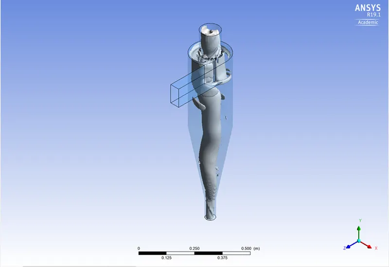
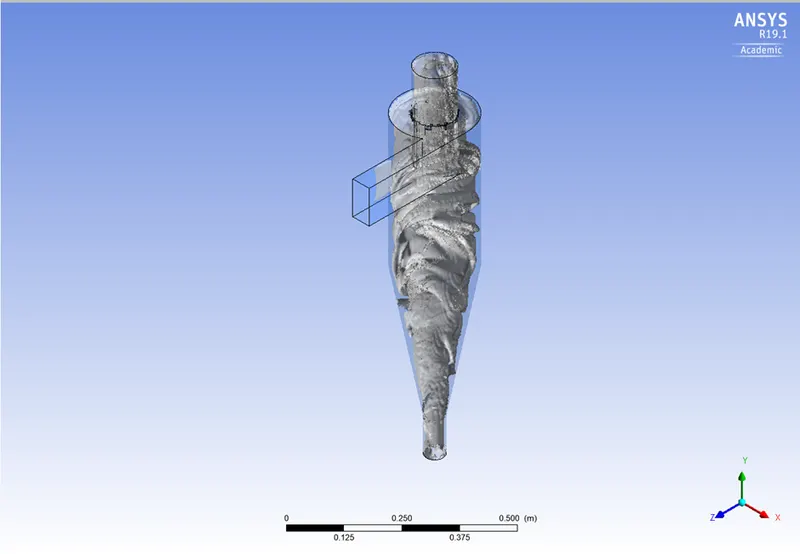
Similar to a centrifuge, cyclone separators operate by continuously supplying unclean air. The unclean flue gas is routed into a chamber of a cyclone separator. The chamber's inside generates a spiral vortex that resembles a tornado. The figure below depicts this spiral creation and the separation. It is simpler for the lighter parts of this gas to be impacted by the vortex and move up it since they have less inertia. Larger particles, on the other hand, have more inertia and are less susceptible to the vortex's influence.
The majority of cyclones are designed to contain and eliminate particles larger than 10 micrometres in diameter. High-efficiency cyclones that are made to be efficient on particles as small as 2.5 micrometres do exist, though. Also, these separators do not work effectively with very large particle matter. Momentum separators or gravity settling chambers are preferable for particulates less than 200 micrometres.
Cyclone separators are among the most affordable particle control equipment. Before the flue gas enters more effective pollution control equipment, they are frequently utilised as a pre-treatment. Hence, before the flue gas enters the fine filtration stages, cyclone separators can be thought of as "rough separators."
Effectiveness:
The majority of cyclones are designed to contain and get rid of debris with a diameter larger than 10 micrometres. Yet, there are high-efficiency cyclones available that are made to work well with particles as small as 2.5 micrometres. These separators are also ineffective against very big particle materials. Gravity-settling chambers or momentum separators are preferable for particulates less than 200 micrometres.
Cyclone separators are among the least expensive particle control equipment available. They are frequently employed as a preliminary step before flue gas enters more efficient pollution control equipment. Cyclone separators can be thought of as "rough separators" because they are used before the flue gas goes through the fine filtration stages.
Procedure:
Pre-processor
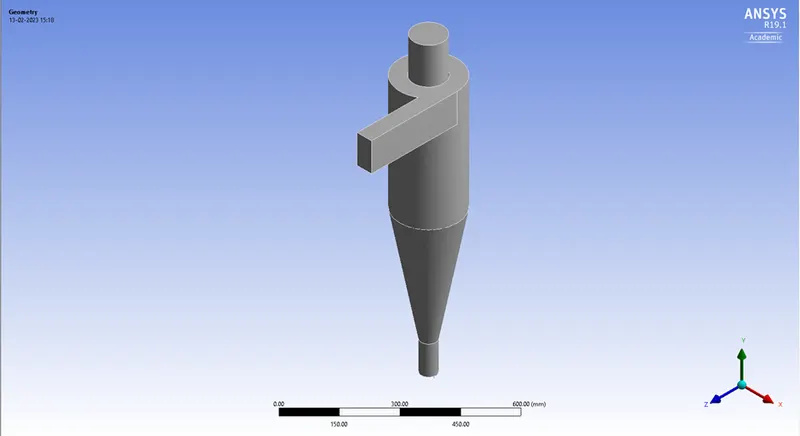
Setup for geometry (Space claim):
- Choose Fluid flow fluent and begin altering the geometry.
- Open Spaceclaim and import the model's step file.
- To analyse the fluid flow of the cyclone separator, volume extracts the model.
- As we are only interested in the fluid flow and not the exterior surface, hide the prior geometry and suppress the physics.
Meshing and its parameters:
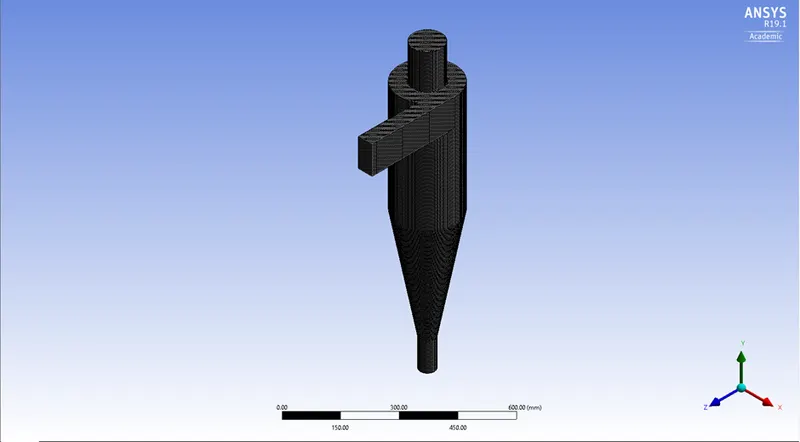
- The model was imported from SpaceClaim, and a 5mm element-size cartesian mesh was deployed. The creation of named selections, such as inlet,outlet1, and outlet, served as the boundary conditions for the solver setup.
- After meshing the model, choose to generate mesh to create the base mesh. However, since mesh refinement affects how many particles enter the inlet, it is preferable to refine the mesh suitably.
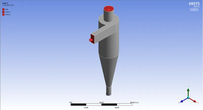
- Giving a named choice: The tool for picking faces is chosen. Names are given to the inlets, top outlet, and bottom outlet. The intake is where the particles enter; the top allows the smaller impurities to leave, while the bottom traps the larger ones.
| Mesh type | Cartesian |
| Mesh size | 5 mm |
| Nodes | 456576 |
| Elements | 427841 |
Named selection (Initial condition):
Solution set-up
Physics set-up:
- Since the fluid flow velocity is quite low, we started with a general configuration and then moved on to a pressure-based steady-state solver. Due to its symmetry, axisymmetry was chosen for 2D space.
- The cyclone separator's orientation is the subject of this analysis. The acceleration caused by gravity needs to be activated, just as it is in the x-y plane. The g value is given as -9.81 in the positive y-axis since gravity's acceleration acts upward. It uses a pressure-based solution. The velocity concept used in the steady state analysis is absolute and normal to the boundary.
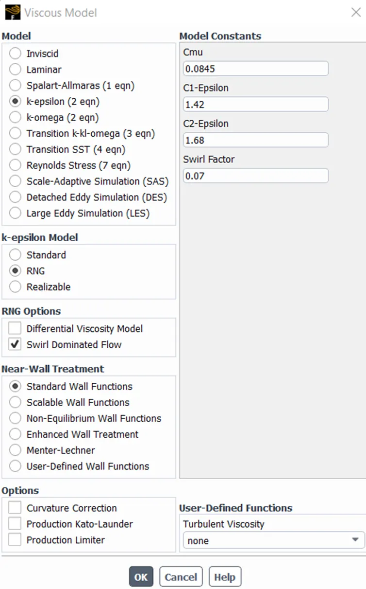
- It is decided to use the K-epsilon(2 equation) model with RNG and swirl-dominated flow. Standard wall functions make up the wall functions.
- The Energy is not activated because temperature is unimportant.
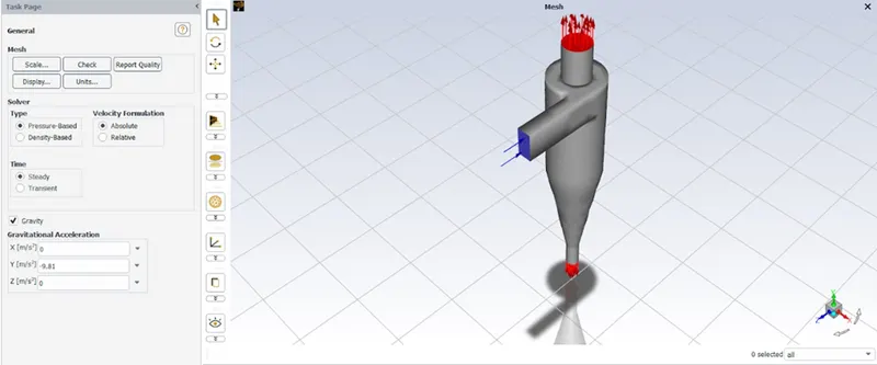
| Solver type | Pressure based |
| Time state | steady state |
| Gravity | Y direction = Negative value (-9.81) |
|
Viscous model
|
k-epsilon RNG turbulence model |
| Swirl dominated flow | |
|
RNG- more than standard case, it enhances the accuracy for swirling flows
|
Viscous and species model:
Discrete phase model:
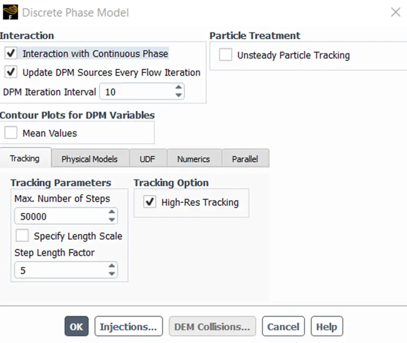
- Discrete phase modelling is the method chosen.
- The continuous phase can be interacted with by the model.
- DPM level of the interval is 10.
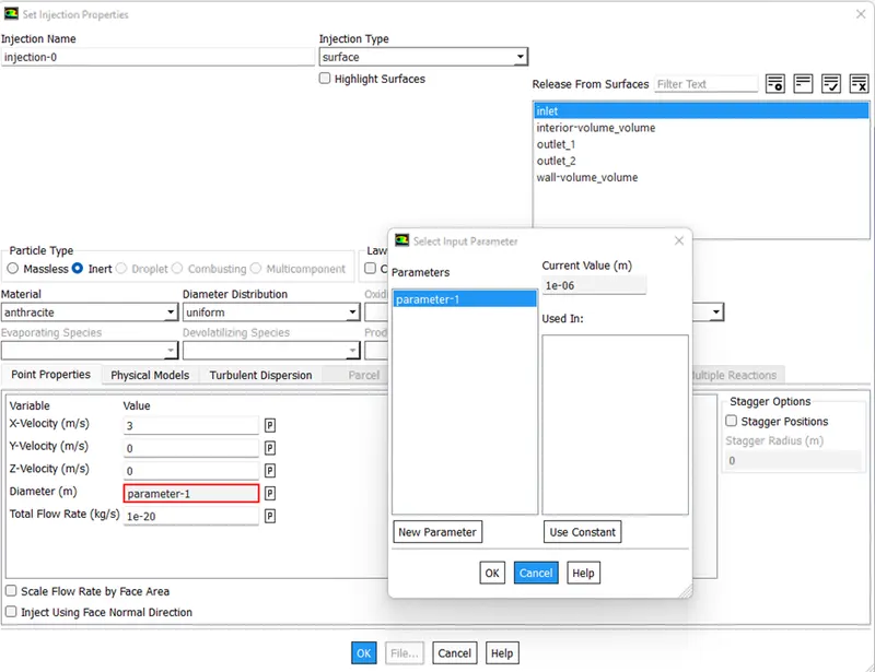
- The sort of particle is inert for injection. Anthracite is chosen from the fluent database. It is emitted from the intake at a speed of 3 m/s in the x direction. Its speed can be changed much more. One micrometre is the particle diameter that was selected for the initial analysis. To determine the separation efficiency, the particle diameter is adjusted from one micrometre to five micrometres.
Injection properties:
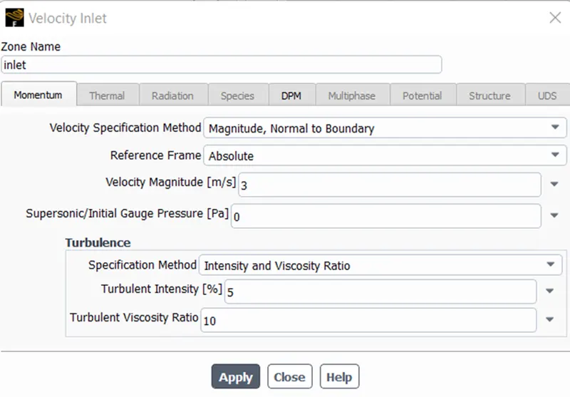
Boundary conditions of velocity inlet:
- Three named selections—inlet, outlet(1)top, and outlet(2) bottom—are given the boundary criteria.
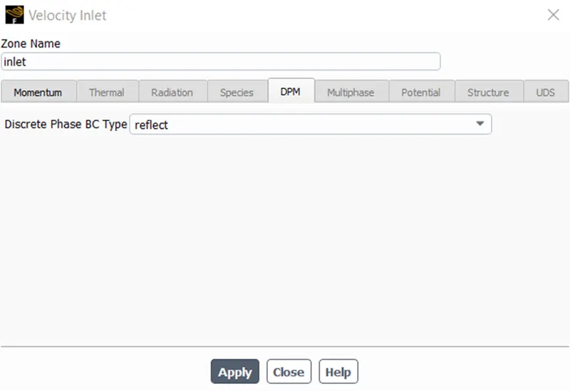
- The momentum requirements for the inlet are absolute and normal to the boundary velocity of 3m/s in the x direction. The DPM state is evident. This means that the particles cannot escape or become stuck in the intake.
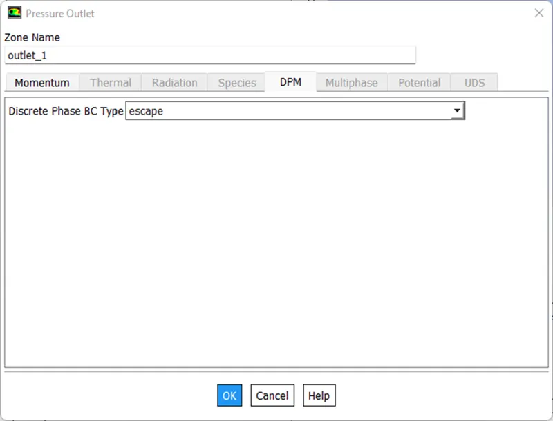
- Momentum condition for the top outlet is a hydraulic pressure condition, and the DPM condition is escaped. This Barrier allows for the escape of particles.
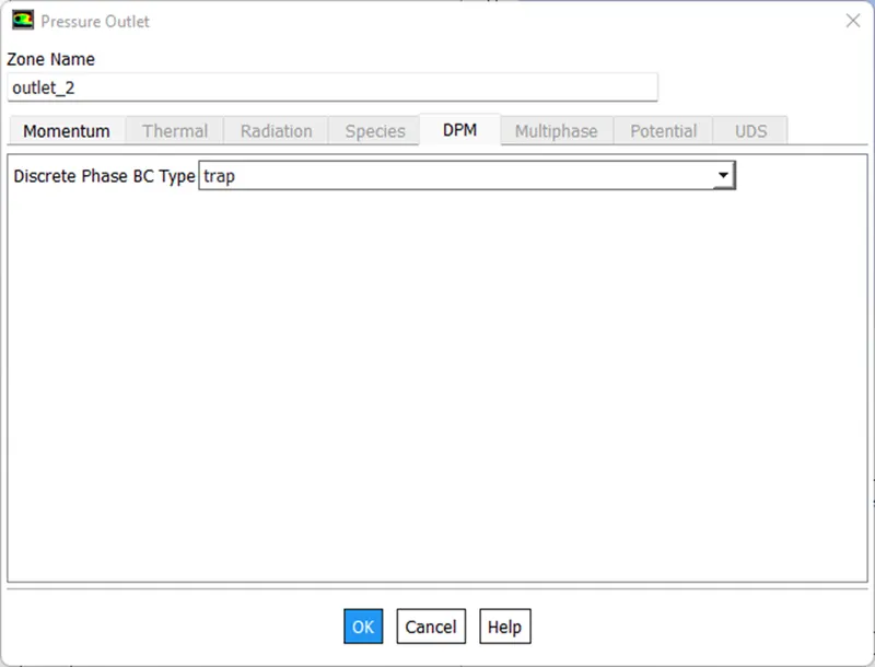
- Alongside a pressure outlet, the bottom outlet's DPM condition is trapped.
Zone names:
| Boundary Conditions |
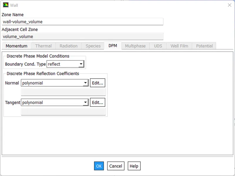
| Inlet and wall: Reflect |
| Outlet(Top): Escape |
|
Outlet(Bottom/dustbin): Trap
|
Solution methods:
- The COUPLED technique is selected for the pressure velocity coupling.
- The gradient is based on cells with the least squares.
- Second-order upwind for pressure, momentum, turbulent kinetic energy, and turbulent dissipation rate.With flow from inlets, standard initialization is carried out.
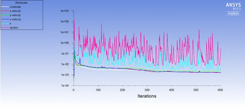
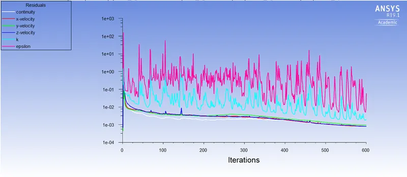
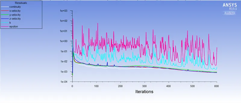
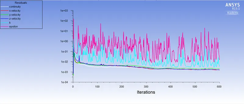
- There are 600 iterations of the analysis.
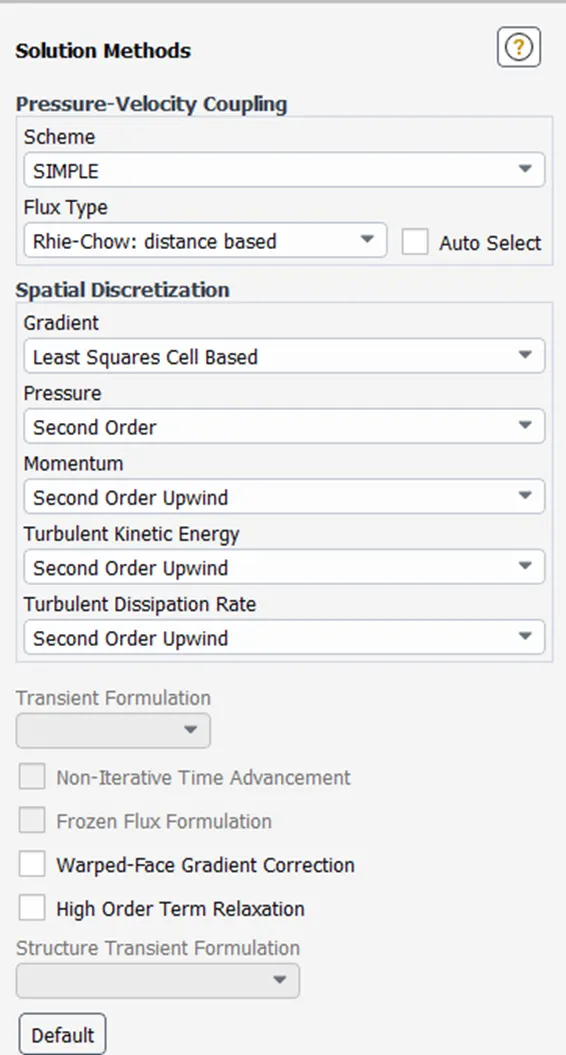
Solution solver
Case 1:
1. Particle Velocity- 3 m/sec & Particle diameter (μm)- 1.00E-06
Residual plots:
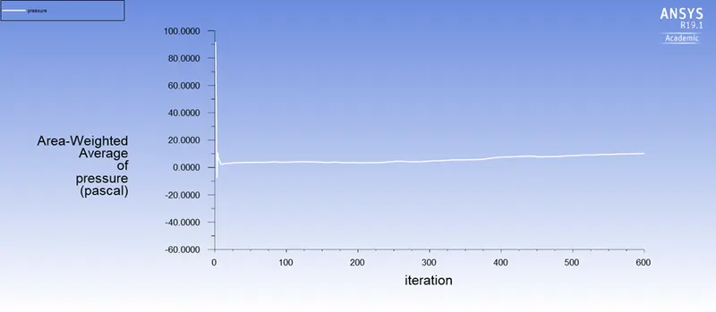
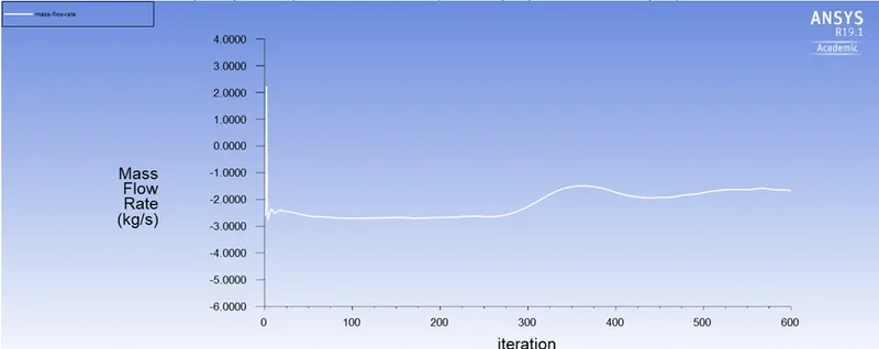
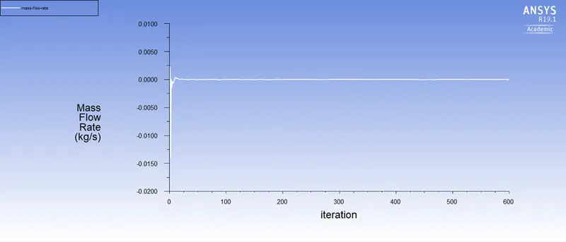
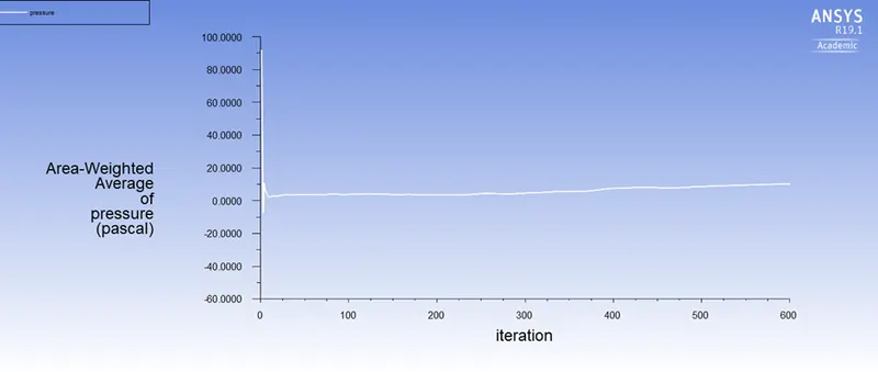
Pressure and mass flow rate:
Post processor
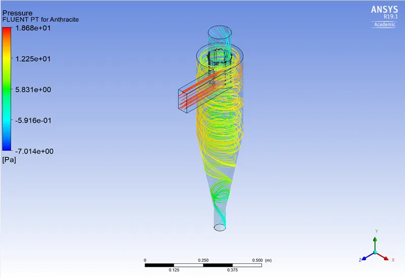
Pressure contour:
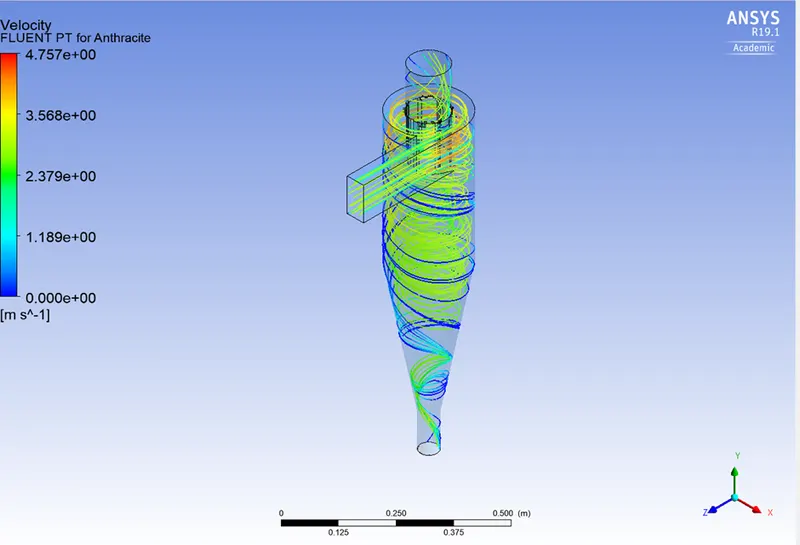
Velocity contour:
Vortex formation:
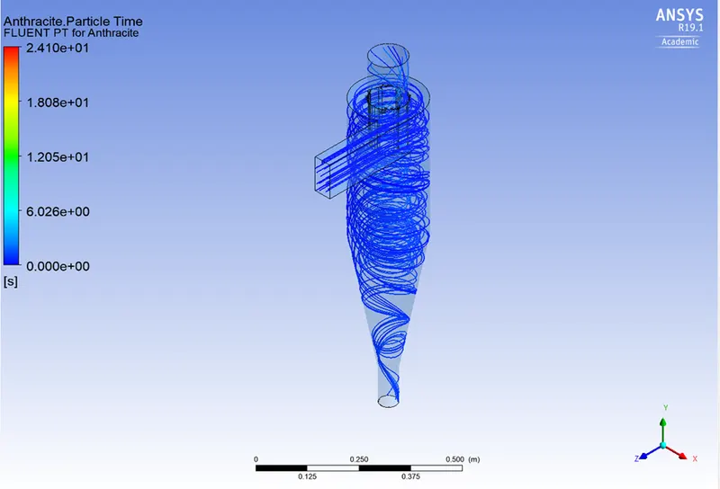
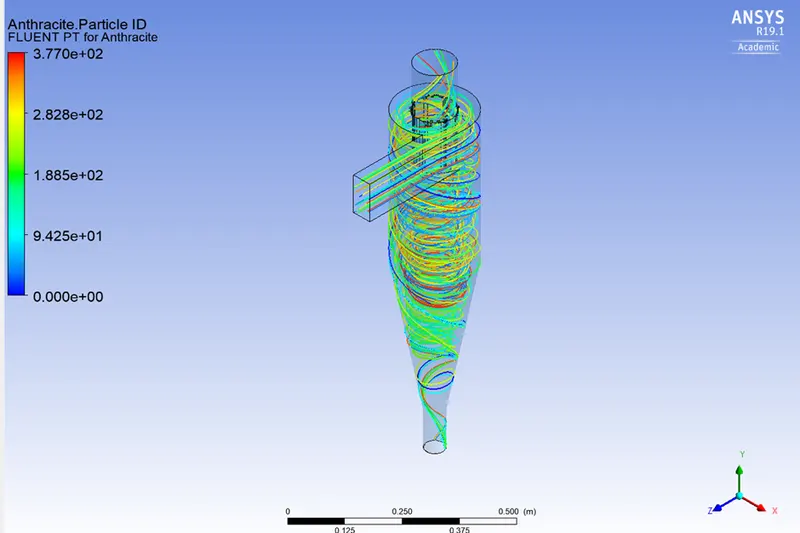
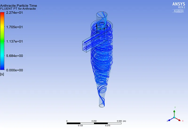
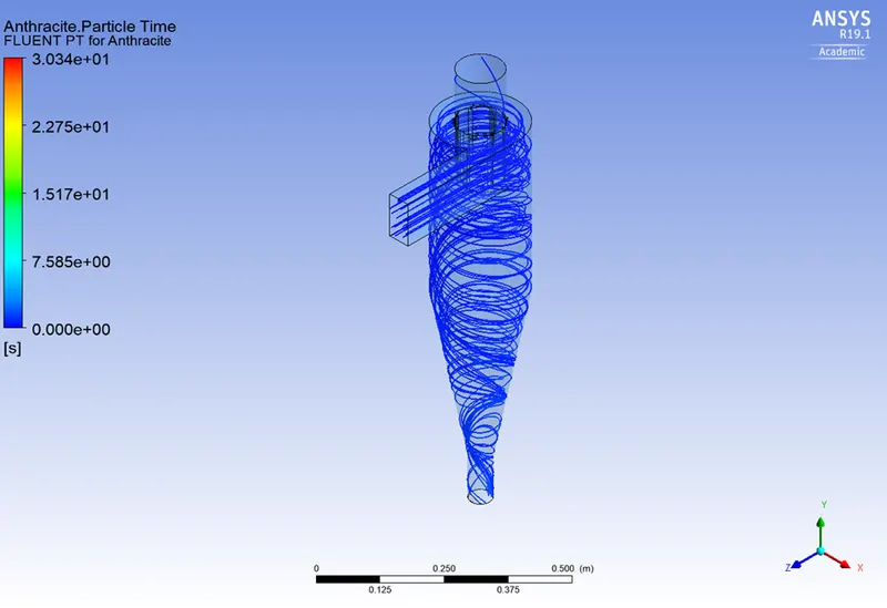
Anthracite particle time and particle ID:
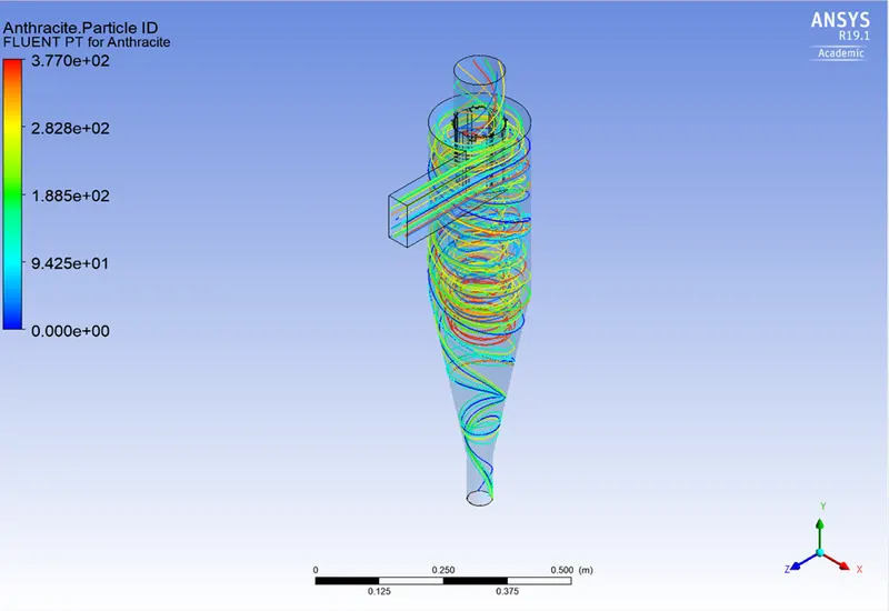
2. Particle Velocity- 3 m/sec & Particle diameter (μm)- 3.00E-06
Residual plots:
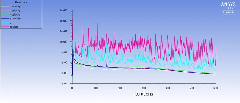
Pressure and mass flow rate:
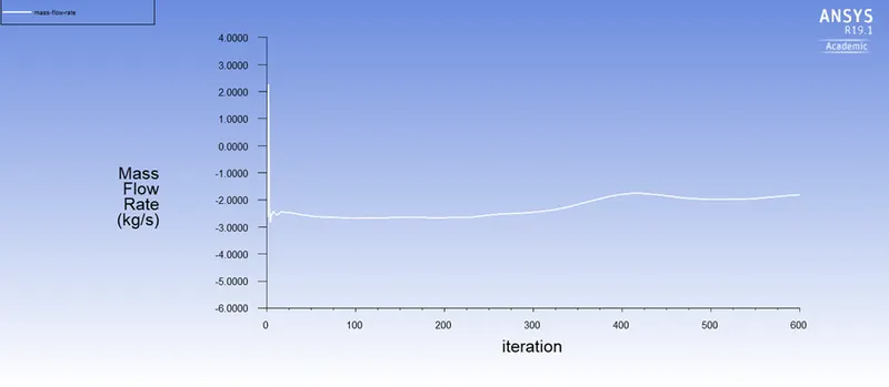
Post processor
Pressure contour:
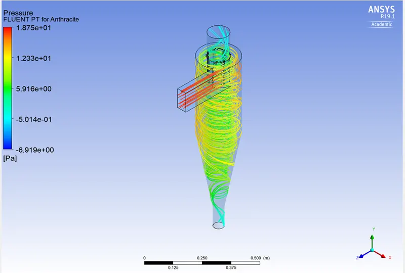
Velocity contour:
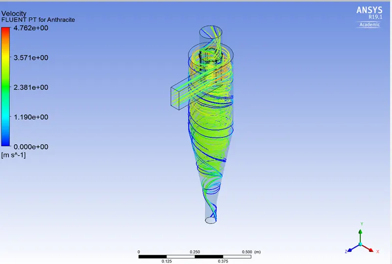
Vortex formation:
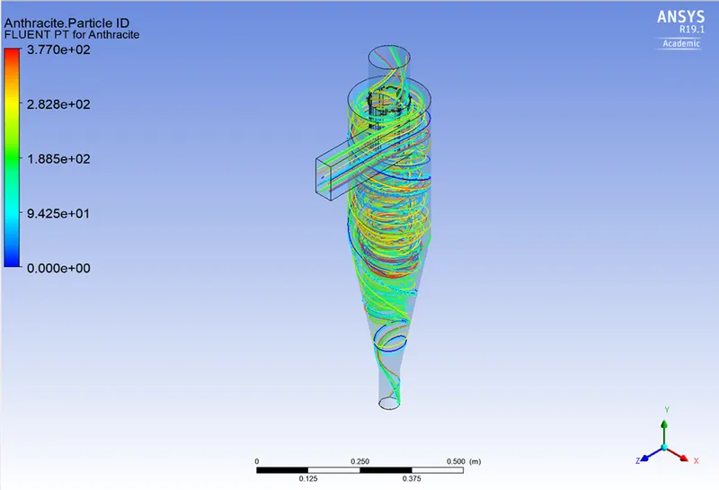
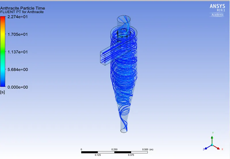
Anthracite particle time and particle ID:
3. Particle Velocity- 3 m/sec & Particle diameter (μm)- 5.00E-06
Residual plots:
Pressure and mass flow rate:
Post processor
Pressure contour:
Velocity contour:
Vortex formation:
Anthracite particle time and particle ID:
Case 2:
1. Particle Velocity- 1 m/sec & Particle diameter (μm)- 5.00E-06
Residual plots:
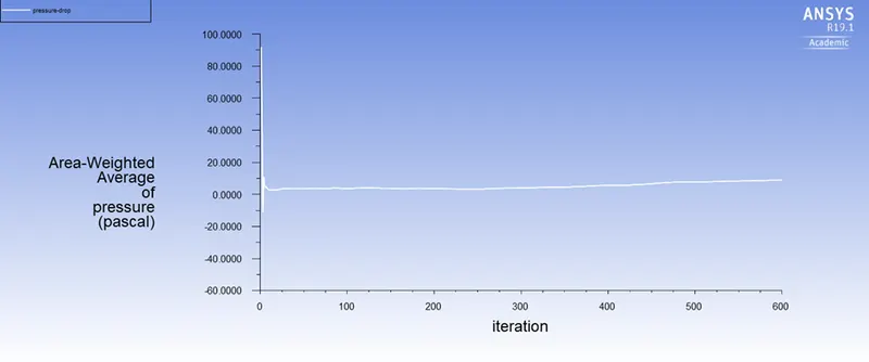
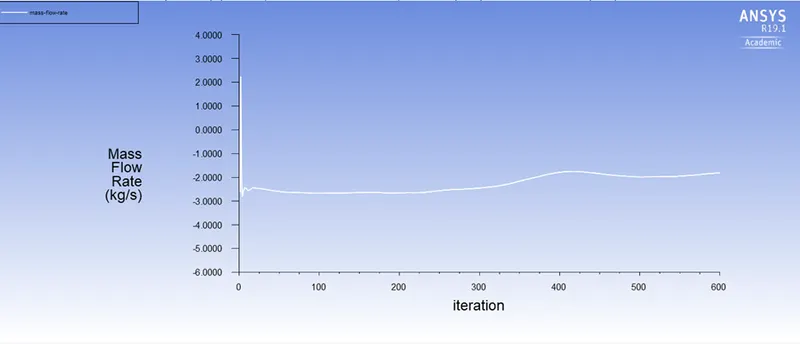
Pressure and mass flow rate:
Post processor
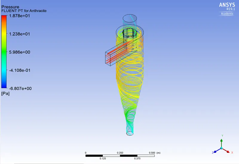
Pressure contour:
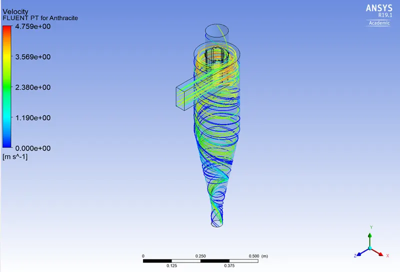
Velocity contour:
Vortex formation:
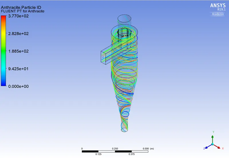
Anthracite particle time and particle ID:
2. Particle Velocity- 3 m/sec & Particle diameter (μm)- 5.00E-06
Residual plots:
Pressure and mass flow rate:
Post processor
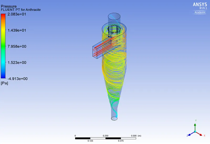
Pressure contour:
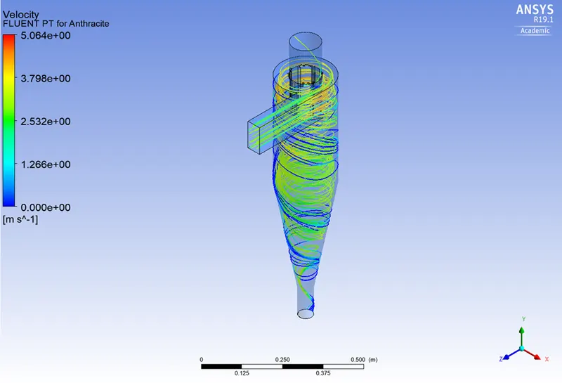
Velocity contour:
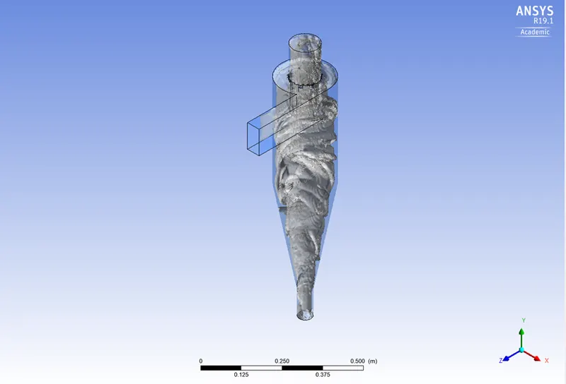
Vortex formation:
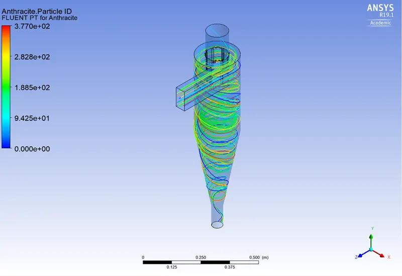
Anthracite particle time and particle ID:
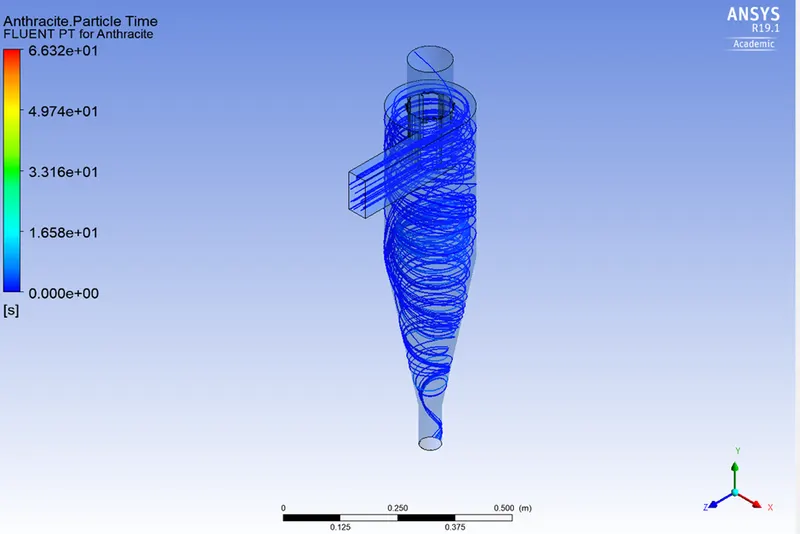
3. Particle Velocity- 5 m/sec & Particle diameter (μm)- 5.00E-06
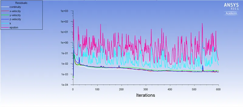
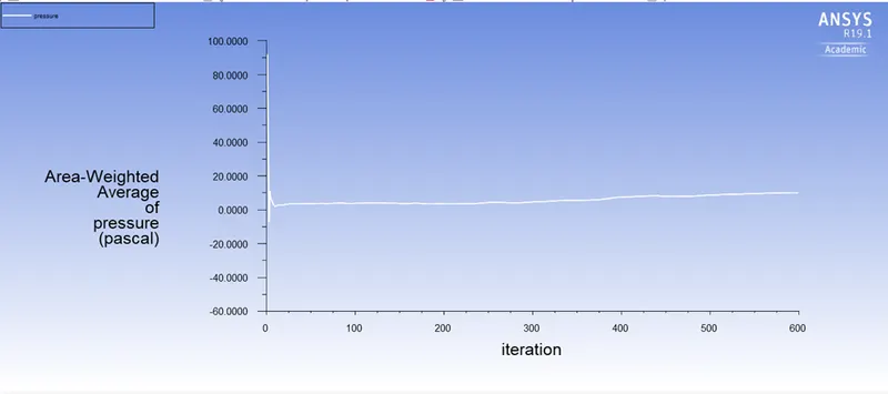
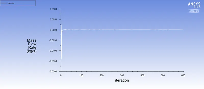
Pressure and mass flow rate:
Post processor
Pressure contour:
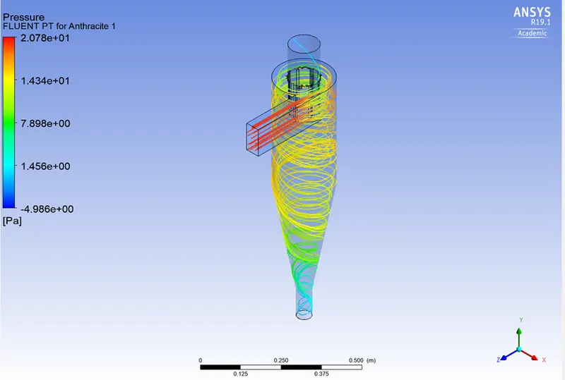
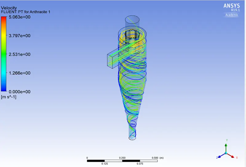
Velocity contour:
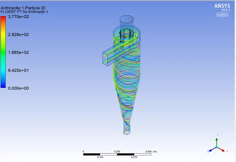
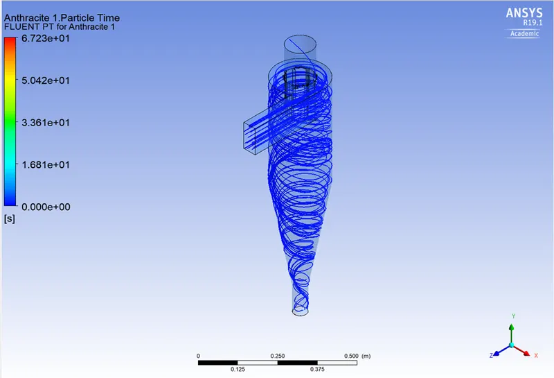
Anthracite particle time and particle ID:
Vortex formation:
Results:
Separator Efficiency:
- The percentage of particles of a particular size that are collected in the cyclone as opposed to those that enter the cyclone is known as separation efficiency. Experience has shown that raising particle mean diameter and density, increasing gas tangential velocity, decreasing cyclone diameter, increasing cyclone length, and extracting gas and solids simultaneously through the cyclone legs all boost the separation efficiency of cyclone separators.
- The separation efficiency in this instance is defined as the ratio of concentration that has been removed from the feed stream to the initial concentration in the feed stream, depending on the particle history data. The ratio of the tracked particle total to the number of captured particles in this scenario.
Pressure Drop:
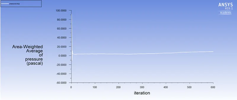
- In a cyclone separator, the pressure drop across the cyclone is crucial. The performance characteristics of a cyclone are substantially impacted by the pressure decrease. The entry and exit losses, friction, and kinetic energy losses within the cyclone all contribute to the overall pressure reduction in the cyclone. The body often experiences the most pressure reduction as a result of whirling and energy loss.
- The difference in total pressure between two places on a fluid-carrying network is known as pressure drop.
- P = Total Outlet Pressure - Total Inlet Pressure is the formula for pressure drop (escape)
- The outlet-top is taken into account in the calculation of pressure drop since in this scenario the escape DPM condition is provided to the outlet-top.
| Case 1 | ||||
| Particle Velocity | Particle diameter varies (μm) | Separation efficiency | Pressure | Mass flow rate |
| 3 m/sec | 1.00E-06 | 38.88% | 8.7773834 | -1.8000774 |
| 3 m/sec | 3.00E-06 | 56.34% | 12.049004 | -1.8960858 |
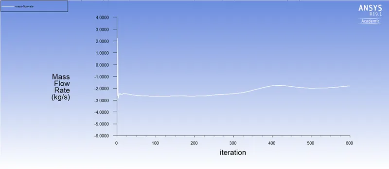
| 3 m/sec | 5.00E-06 | 52.11% | 10.18179 | -2.5711917 |
| Case 2 | ||||
| Particle Velocity varies | Particle diameter (μm) | Separation efficiency | Pressure | Mass flow rate |
| 1 m/sec | 5.00E-06 | 73.54% | 10.15716 | -1.9912717 |
| 3 m/sec | 5.00E-06 | 44.17% | 10.18179 | -2.5711917 |
| 5 m/sec | 5.00E-06 | 48.90% | 10.13406 | -1.7701998 |
Anthracite particles:
| number tracked | escaped | aborted | trapped | evaporated | incomplete | incomplete_parallel |
| 378 | 140 | 0 | 147 | 0 | 91 | 0 |
| 378 | 116 | 0 | 213 | 0 | 49 | 0 |
| 378 | 38 | 0 | 197 | 0 | 143 | 0 |
| 378 | 56 | 0 | 278 | 0 | 44 | 0 |
| 378 | 41 | 0 | 167 | 0 | 170 | 0 |
| 378 | 40 | 0 | 185 | 0 | 153 | 0 |
Inference:
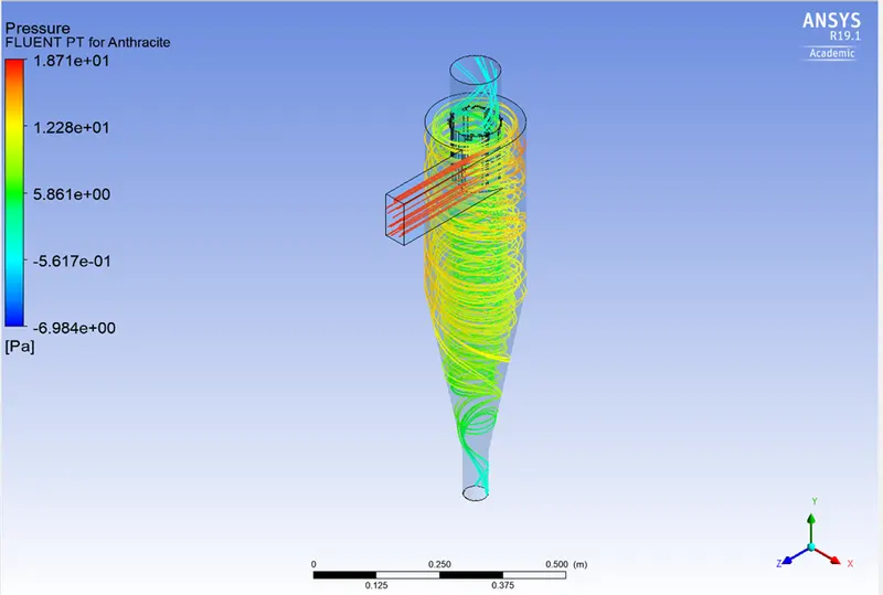
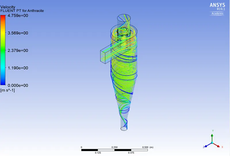
- We may deduce that the pressure is higher close to the wall section which creates the outer vortex from the pressure velocity charts shown above. The creation of a low-pressure area at the centre of the cyclone separator as a result of higher pressure along the wall causes lighter particles to escape from the top outlet and heavier particles to gather at the bottom outlet.
- With air and particle velocity both set to 3 m/s, simulations are run for particle sizes ranging from 1 m to 5 m. From the video, it can be seen that smaller particles escape via outlet 1 while larger particles are trapped at the bottom outlet.
- Particle size, density, and cyclone design all affect how well cyclones gather waste material. Particle size, density, intake duct velocity, cyclone body length, number of gas revolutions, the ratio of cyclone body diameter to gas exit diameter, inlet dust loading, and smoothness of cyclone inner wall all tend to boost cyclone efficiency.
- Increases in characteristics including gas viscosity, cyclone body diameter, gas exit diameter, gas inlet duct area, gas density, and air leakage into dust output will result in a drop in the cyclone's efficiency.
- Efficiency rises with increasing intake velocity or particle size.
- The pressure decrease across the cyclone has an impact on the cyclone separator's collection effectiveness. The energy needed for the gas to transport the particles is here measured indirectly by pressure loss. Particle size and air inlet velocity both affect pressure drop.
- There is a pressure drop due to the following factors:
1. Loss brought caused by the gas in the cyclone chamber expanding.
2. Loss brought on by kinetic energy in rotation.
3. Loss brought induced by frictional wall forces