Week 8 - Simulating Cyclone separator with Discrete Phase Modelling
AIM -
A Steady-state simulation for analysis of the Cyclone Separator is to be performed in Ansys Fluent in order to calculate the separator efficiency and the pressure drop.
INTRODUCTION -
Cyclone Separators are machines that use the centrifugal force produced by a spinning fluid stream to separate the particles from the carrier fluid. They are perfect for use as pre-cleaners for more expensive final control devices like baghouses or electrostatic precipitators due to their straightforward design, low capital cost, and nearly maintenance-free operation. Because of their robust design and flexible component materials, cyclones are especially well suited for high temperature and pressure conditions.
Cyclone Separators are used to remove large particles from the air for both pollution control and process use. Extreme applications include coal dust removal in power plants and use as a spray dryer or gasification reactor.
Cyclone separator Working -
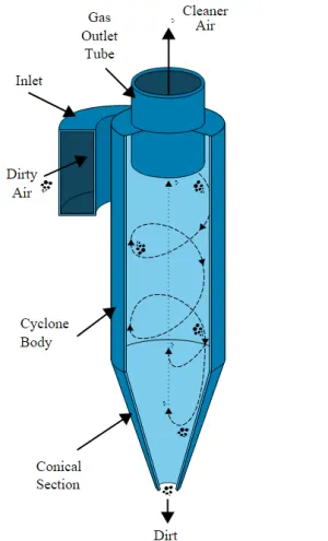
Cyclone separators operate similarly to centrifuges, but with a continuous supply of dirty air. Dirty flue gas is fed into a chamber in a cyclone separator. The interior of the chamber generates a spiral vortex, similar to that of a tornado. The separation and spiral formation. Because the lighter components of this gas have less inertia, they are more easily influenced by the vortex and travel up it. Larger particulate matter components, on the other hand, have more inertia and are less easily influenced by the vortex. Because these larger particles have difficulty following the high-speed spiral motion of the gas and vortex, they collide with the container's inside walls and fall into a collection hopper. These chambers are shaped like an upside-down cones to encourage particle collection at the container's bottom. The cleaned flue gas escapes through the chamber's top.
 |
Cyclone separator Efficiency -
Cyclone separators can typically remove between 50 and 99% of all particulate matter in the flue gas. The ability of the cyclone separators to remove this matter is largely determined by particle size. When there is a lot of lighter particulate matter, fewer of these particles can be separated out. As a result, cyclone separators perform best on flue gases containing a high concentration of large particulate matter. The efficiency can reach 99% for particles bigger than 5 µm and can be operated at very high dust loading.
THEORY -
Four empirical models to calculate cyclone separator efficiency are;
1) IOZIA AND LEITH MODEL -
Based on a force balance, Iozia and Leith developed their logistic model. A particle carried by the vortex is thought to be subject to two forces: flow resistance and centrifugal force.
2) LI AND WANG MODEL -
The Li and Wang model takes into account turbulent diffusion at the cyclone wall as well as particle bounce or re-entrainment. It is possible to express the particle distribution in the cyclone analytically in two dimensions.
3) KOCH AND LICHT MODEL -
The distribution of gas residence times within cyclones and the inherently turbulent nature of cyclones were recognized by Koch and Licht collection theory.
4) LAPPLE MODEL -
Without taking into account flow resistance, the Lapple model was developed based on force balance. Lapple made the supposition that a particle entering the cyclone is dispersed uniformly throughout the inlet opening. 50% of the particle that moves from the cyclone's inlet half-width to the wall is efficiently collected.
The cyclone efficiency predicted by the Li and Wang model is very accurate at room temperature. The Lapple, Koch, and Licht models have a significant overestimation of efficiency for small particles and a significant underestimation of efficiency for large particles. The logistic model developed by Iozia and Leith exhibits good agreement with experimental data for cyclones with diameters between 0.25 and 0.4 meters. It cannot, however, accurately predict the efficiency of small cyclones (D 0.1m). Only cyclones with diameters around 0.25 m can be efficiently predicted using the Iozia and Leith model. The Lapple model exhibits a decent level of prediction when two extreme conditions, such as extremely high temperature and pressure, are present. Under high-pressure operating conditions, the Koch and Licht model exhibits a good cyclone efficiency prediction. While the Lapple model is demonstrated to be the most accurate model for predicting cyclone efficiency at high operating temperatures.
SOLVING & MODELLING APPROACH -
Each CFD simulation follows the workflow listed below.;
1) Problem finding
2) Pre-processing
3) Processor or Solver
4) Post-processing
In order to prepare the model for further processing in SpaceClaim, the geometry had to be simplified, which included extracting the fluid volume. Later, the proper mesh was created over the entire geometry in the mesh file, and Named Selection was completed. After the relevant solver settings were entered in the Setup file, the simulation was run for five different cases in accordance with the conditions mentioned in the problem statement.
|
Case No. |
Particle Velocity |
Particle Diameter |
|
1 |
3 m/sec |
1 μm |
|
2 |
3 μm |
|
|
3 |
5 μm |
|
|
4 |
1 m/sec |
|
|
5 |
5 m/sec |
Results from the post-processing were computed and saved as plots and contours in the Result file. Considering the findings, conclusions were drawn.
PRE-PROCESSING -
In SpaceClaim, the geometry model of the cyclone separator was imported followed by extraction of the fluid volume of the model using the 'Volume Extract' command under the 'Prepare' tool. The external thickness, that is, the solid part, was suppressed using the 'Suppress for Physics' command as the simulation is concerned with fluid volume only and the solid part was not required for further analysis. 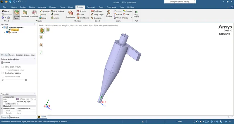
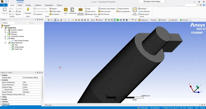
In the Mesh file, a structural mesh was created over the body using the 'Body Fitted Cartesian' method with a baseline mesh size of 5 mm.
Here, it is considered that number of elements at the inlet is approximately equal to the number of fluid particles at the inlet, that is, one particle will be injected from each element at the inlet.
Named Selection:
|
Sr No. |
Component |
Name Assigned |
|
1 |
Inlet |
Inlet |
|
2 |
Outlet (Top) |
Outlet Escape |
|
3 |
Outlet (Bottom) |
Outlet Trap |
SOLVER -
In the Setup file, provide the following solver settings:
|
Fluent Setup |
||
|
Sr. No. |
Setup |
Command |
|
1 |
Solver Type |
Pressure based |
|
2 |
Solver Time |
Steady State |
|
3 |
Gravity |
ON |
|
4 |
Viscous Model |
K epsilon (RNG – Swirl Dominated Flow) |
|
5 |
Discrete Phase Model (DPM) |
Enabled |
|
6 |
Injection (Anthracite Particles) |
Surface Injection |
|
7 |
Particle Diameter |
According to the case |
|
8 |
Particle Velocity |
According to the case |
|
9 |
Material (Fluid) |
Air |
|
10 |
Inlet |
Velocity Inlet (velocity value acc. to the case) |
|
DPM – Reflect |
||
|
11 |
Outlet Escape |
Pressure Outlet |
|
DPM – Escape |
||
|
12 |
Outlet Trap |
Pressure Outlet |
|
DPM – Trap |
||
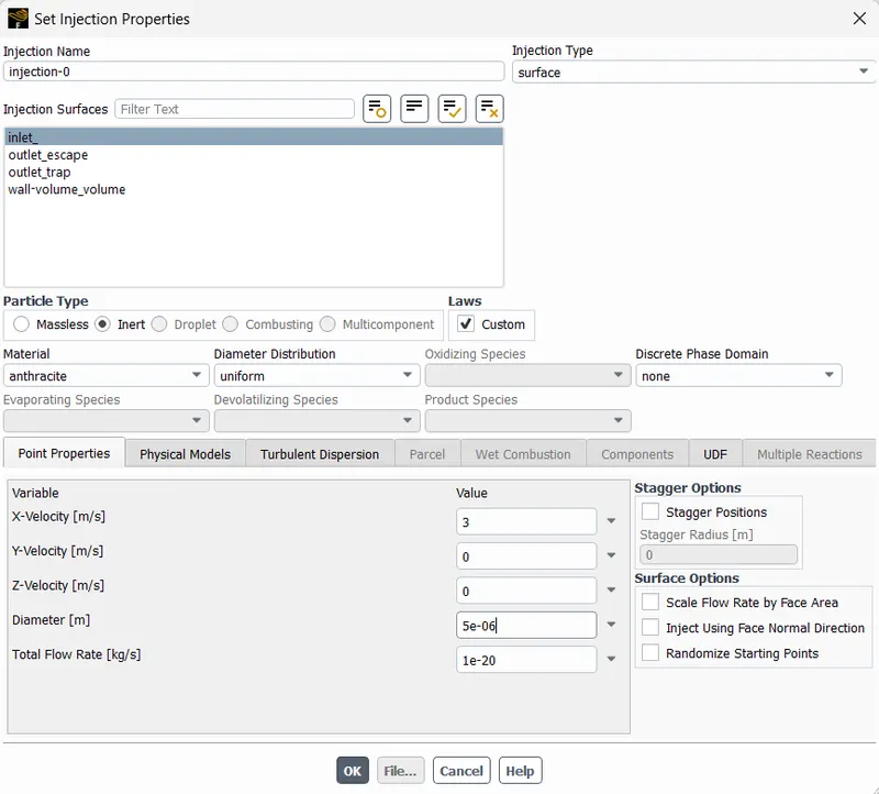
In Discrete Phase Model (DPM), first, we need to enable the 'Interaction with Continous Phase'. Later, create the Injection method and set the injection properties as;
- Injection Type - Surface
- Injection Surfaces - Inlet
- Material - Anthracite
- Diameter Distribution - Uniform
- Point Properties - Corresponding values of velocity and diameter
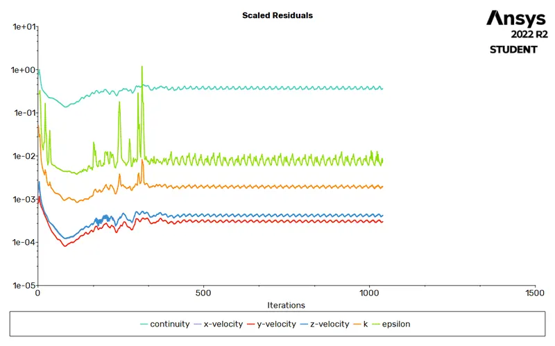
Initialize the solver settings as a hybrid type and run the simulation for all cases for a specified number of iterations until the number of incomplete particles becomes zero.
|
Case No. |
Scaled Residuals Plots |
|
1 |
|
|
2 |
|
|
3 |
|
|
4 |
|
|
5 |
|
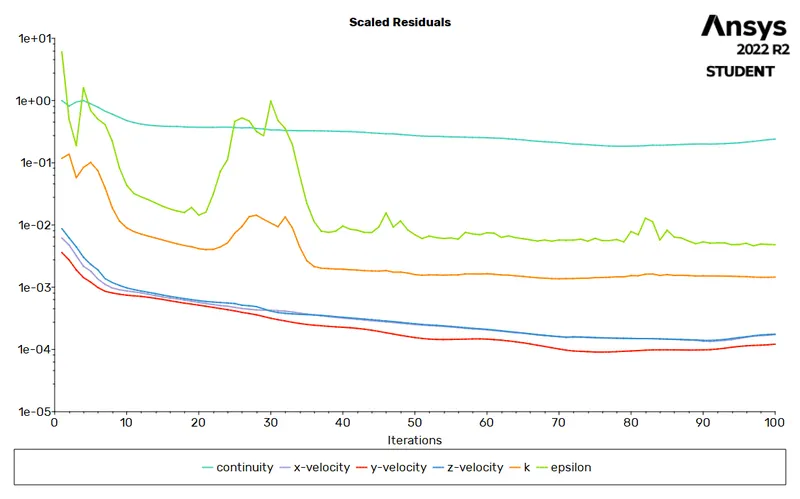
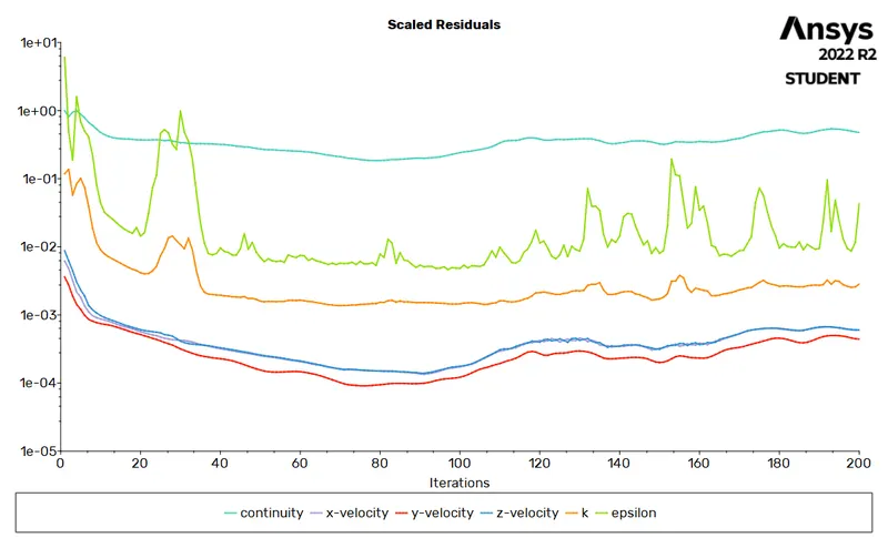
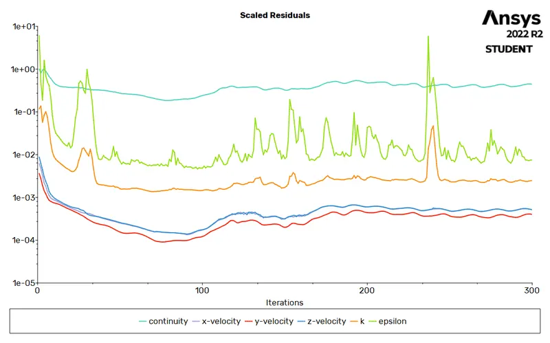
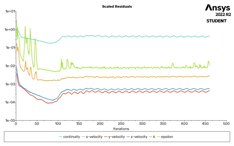
The Separation efficiency of a cyclone separator is given as;
`eta = frac{N_(trapped)}{N_(tracked)}`
where `N_(trapped` = number of particles trapped at the end of the simulation,
`N_(tracked)` = number of particles tracked at the end of the simulation
Compute the number of particles tracked, escaped, and trapped at the end of each simulation and calculate the cyclone separator efficiency using the relation mentioned above. Also, compute the total pressure at the inlet and the outlet escape and calculate the total pressure drop.
POST-PROCESSING -
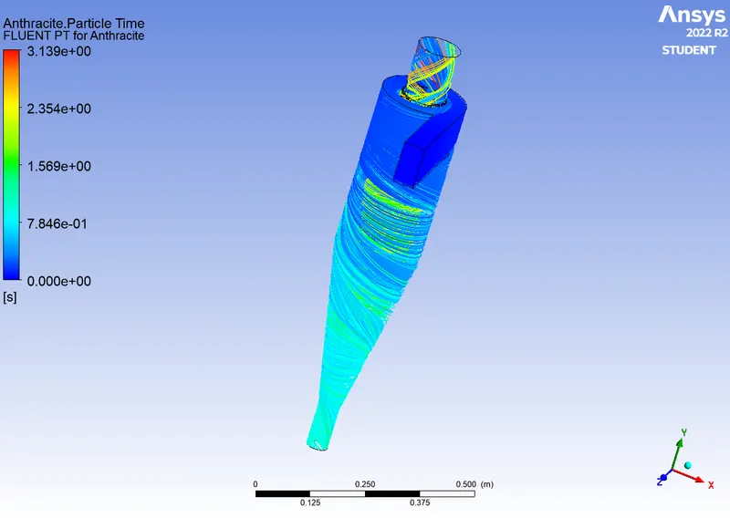
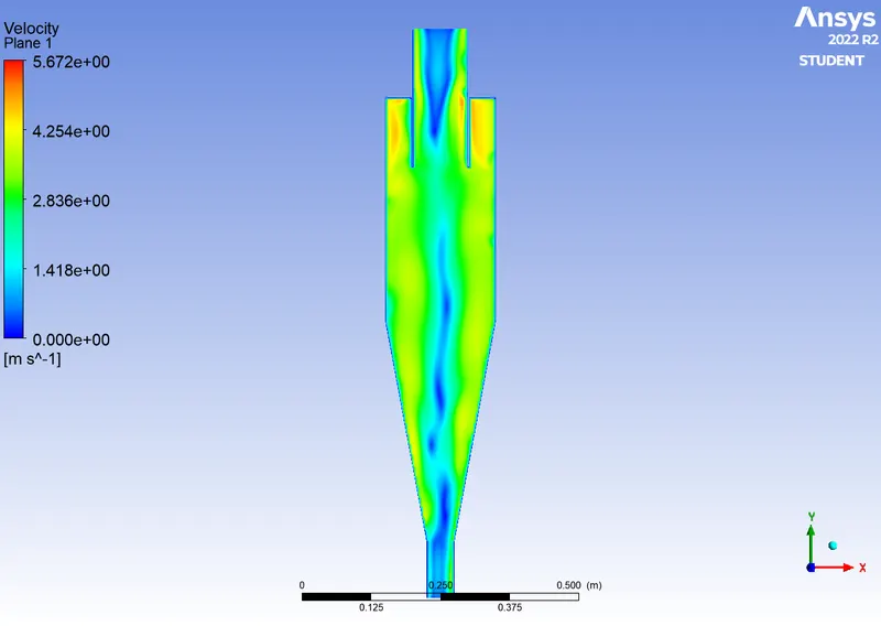
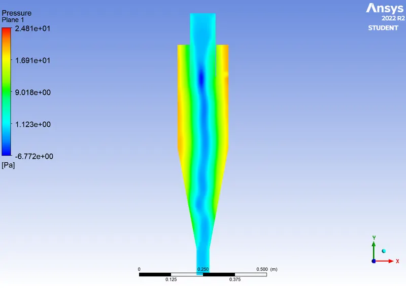
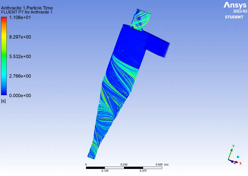
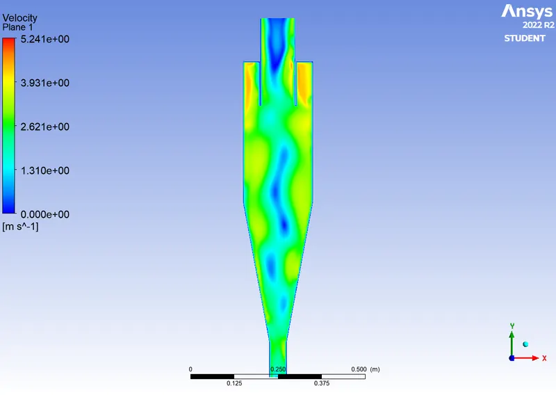
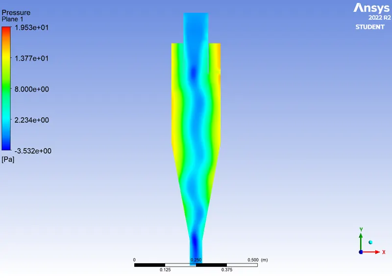
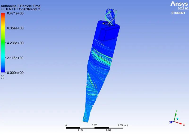
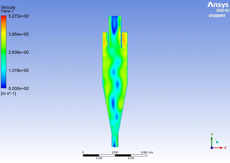
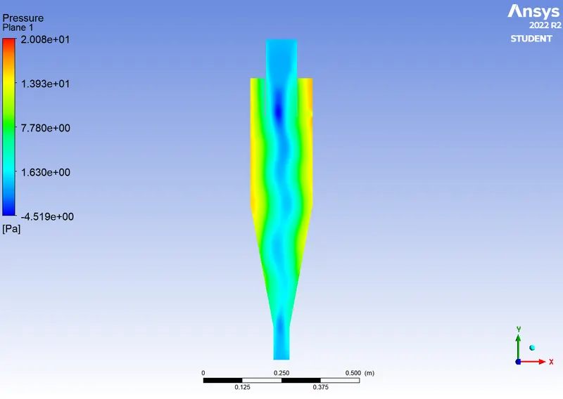
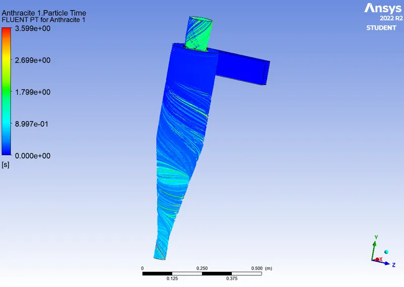
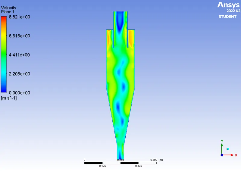
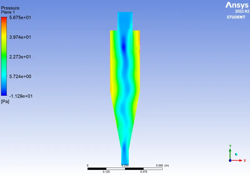
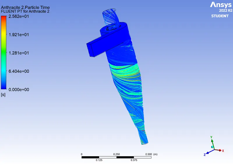
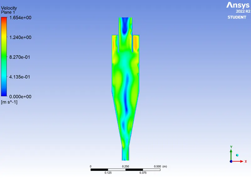
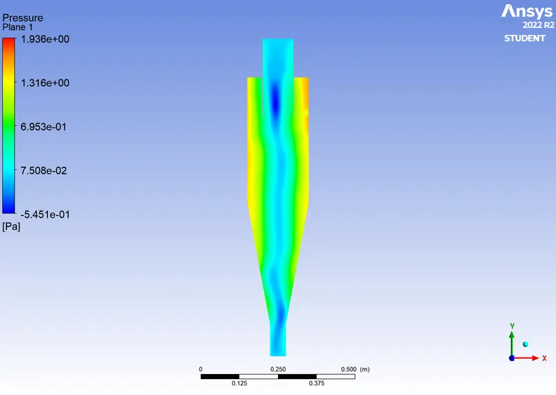
In the Result file, we need to plot the contours for Pressure, Velocity, and Anthracite Particle Time.
Anthracite Particle Time contour was plotted using the following;
In the Setup file,
File > Export > Particle History Data > save the file to the desired directory
In the Result file,
Import > Fluent Particle Track File > select the saved file
RESULTS -
|
Case No. |
Contours |
||
|
Anthracite Particle Time |
Velocity |
Pressure |
|
|
1 |
|
|
|
|
2 |
|
|
|
|
3 |
|
|
|
|
4 |
|
|
|
|
5 |
|
|
|
CONCLUSION -
|
Case No. |
Particle Velocity (m/s) |
Particle Diameter (μm) |
Particles Tracked |
Particles Escape |
Particles Trapped |
Efficiency (%) |
Total Pressure (Inlet) [Pa] |
Total Pressure (Outlet Escape) [Pa] |
Pressure Drop [Pa] |
|
1 |
3 |
1 |
378 |
94 |
284 |
75 |
29.37 |
4.67 |
24.7 |
|
2 |
3 |
3 |
378 |
55 |
323 |
85 |
24.17 |
11.44 |
12.73 |
|
3 |
3 |
5 |
378 |
41 |
337 |
89 |
24.69 |
3.29 |
21.4 |
|
4 |
1 |
5 |
378 |
138 |
240 |
63.5 |
69 |
9.14 |
59.86 |
|
5 |
5 |
5 |
378 |
53 |
325 |
86 |
2.48 |
0.33 |
2.15 |
- The cyclone separator's efficiency is high when the particle velocity is high. The efficiency of the cyclone separator increases with particle diameter, so at particle diameter = 1, the efficiency is lower than at particle diameter = 5.
- However, particle velocity dominates over the particle diameter with regard to the efficiency of the cyclone separator.
- The pressure drop is inversely proportional to the inlet velocity, with a high-pressure drop for low inlet velocity and a low-pressure drop for high inlet velocity.
REFERENCE -
Thus, the steady-state simulation for analysis of the Cyclone Separator was performed in Ansys Fluent.