Week 8 - Simulating Cyclone separator with Discrete Phase Modelling
Simulating Cyclone separator with Discrete Phase Modelling
Aim:To perform analysis on cyclone separator and calculate the separation efficiency and pressure drop.
Objectives:
- To write a few words about any four empirical models used to calculate the cyclone separator efficiency.
- To perform an analysis on a given cyclone separator model by varying the particle diameter from 1 μm to 5 μm and calculate the separation efficiency in each case. Discuss the results. [Use both the velocity's as 3m/sec.]
- To perform an analysis on a given cyclone separator model by varying the particle velocity from 1 m/sec to 5 m/sec and calculate the separation efficiency and pressure drop in each case. Discuss the results. [Use particle diameter size as 5 μm for all cases & keep flow velocity same as particle velocity]
Boundary Conditions:
Inlet and wall:- Reflect
Outlet(Top):- Escape
Outlet(Bottom/dustbin) - Trap
Theory:
Cyclones are devices that employ a centrifugal force generated by a spinning gas stream to separate particles from the carrier gas. Their simple design, low maintenance costs, and adaptability to a wide range of operating conditions such as sizes and flow rates make cyclones one of the most widely used particle removal devices. By using suitable materials and methods of construction, cyclones may be adapted for use in extreme operating conditions:
- high temperature
- high pressure
- corrosive gases
Cyclones are important particle removal devices in both engineering and process operations.An inaccuracy in cyclone efficiency prediction may result in an inefficient design of cyclone separators. Models topredict the behaviour of cyclones are usually empirical. It remains largely a process of trial and error, since empiricalcyclones models are only applicable to specific cyclone
geometries.
The four different cyclone efficiency empirical models are namely Lapple , Koch and Licht , Li and Wang , and Iozia and Leith.
LAPPLE MODEL
Lapple (1951) model was developed based on force balance without considering the flow resistance. Lapple assumed that a particle entering the cyclone is evenly distributed across the inlet opening. The particle that travels from inlet half width to the wall in the cyclone is collected with 50% efficiency.The semi empirical relationship developed by Lapple [1] to calculate a 50% cut diameter, dpc, is
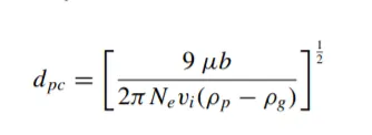
where Ne is the number of revolutions
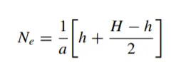
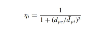
The efficiency of collection of any size of particle is given by,
KOCH AND LICHT MODEL
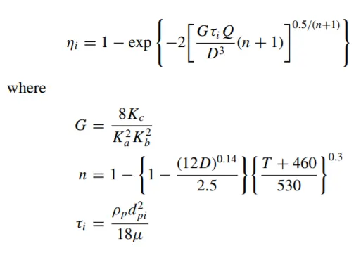
Koch and Licht (1977) collection theory recognized the inherently turbulent nature of cyclones and the distribution of gas residence times within the cyclone. Koch and Licht describe particle motion in the entry and collection regions with the additional following assumptions:
The tangential velocity of a particle is equal to the tangential velocity of the gas flow, i.e., there is no slip in the tangential direction between the particle and the gas.
The tangential velocity is related to the radius of cyclone by:uRn = constant.
A force balance and an equation on the particles collection yields the grade efficiency ηi
LI AND WANG MODEL
The Li and Wang (1989) model includes particle bounce or re-entrainment and turbulent diffusion at the cyclone wall. A two-dimensional analytical expression of particle distribution in the cyclone is obtained.
Li and Wang model was developed based on the following assumptions:
- The radial particle velocity and the radial concentration profile are not constant for uncollected particles within the cyclone.
- Boundary conditions with the consideration of turbulent diffusion coefficient and particle bounce reentrainment on the cyclone wall are:
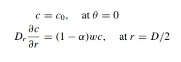
The concentration distribution in a cyclone is given as:
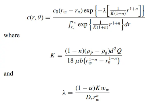
The resultant expression of the collection efficiency for particle of any size is given as
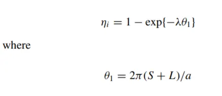
IOZIA AND LEITH MODEL
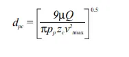
Iozia and Leith (1990) logistic model is a modified version of Barth (1956) model which is developed based on force balance. The model assumes that a particle carried by the vortex endures the influence of two forces: a centrifugal force, Z, and a flow resistance, W. Core length, zc, and core diameter,dc, are given as
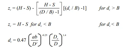
The addition made by Iozia and Leith on the original Barth (1956) model are the core length zc and slope parameter β expression which is derived based on the statistical analysis of experimental data of cyclone with D = 0.25 m. The collection
efficiency ηi of particle diameter dpi can be calculated from
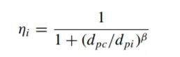
where dpc is the 50% cut size given by Barth (1956)
Solving and Modelling:
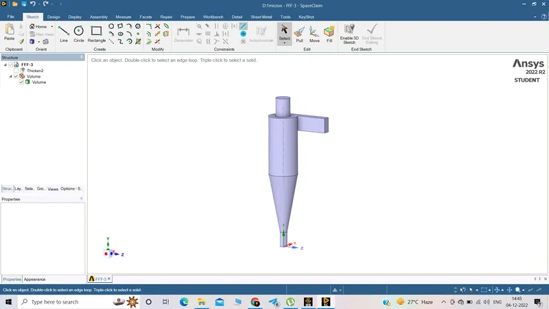
- Geometry creation:
Importing 3D model in spaceclaim and performing volume extraction
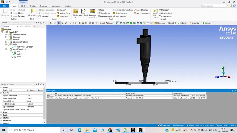
- Meshing:
Refining mesh element, inserting cartesian method and creating named selection i.e inlet,outlet1 and outlet 2
- Setting up solver:
CASE 1 :Performing analysis on the given cyclone separator model by varying the particle diameter from 1 μm to 5 μm
flow velocity= particle velocity=3m/sec
- Particle diameter of 1 µm, while maintaining the particle velocity at 3 m/s:
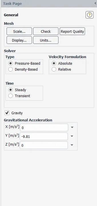
General setup of the simulation:
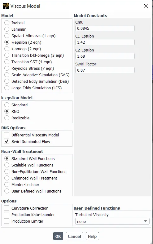
Selecting K-epsilon RNG model for better result :(RNG means ReNormalization Group)
The RNG model in FLUENT provides an option to account for the effects of swirl or rotation by modifying the turbulent viscosity appropriately.
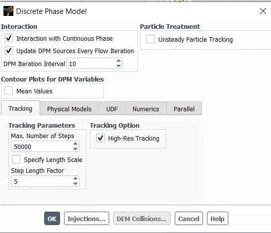
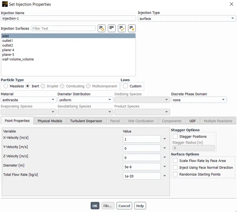
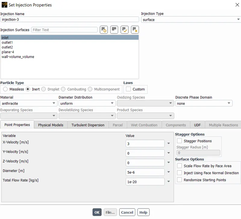
Discrete phase is turned on and set injection properties:
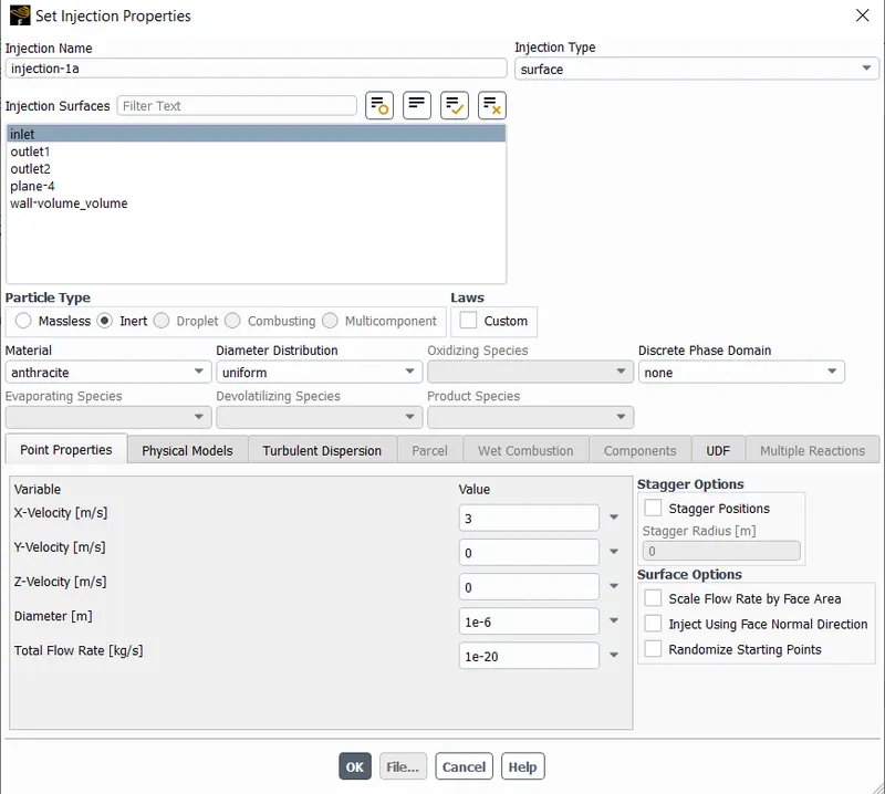
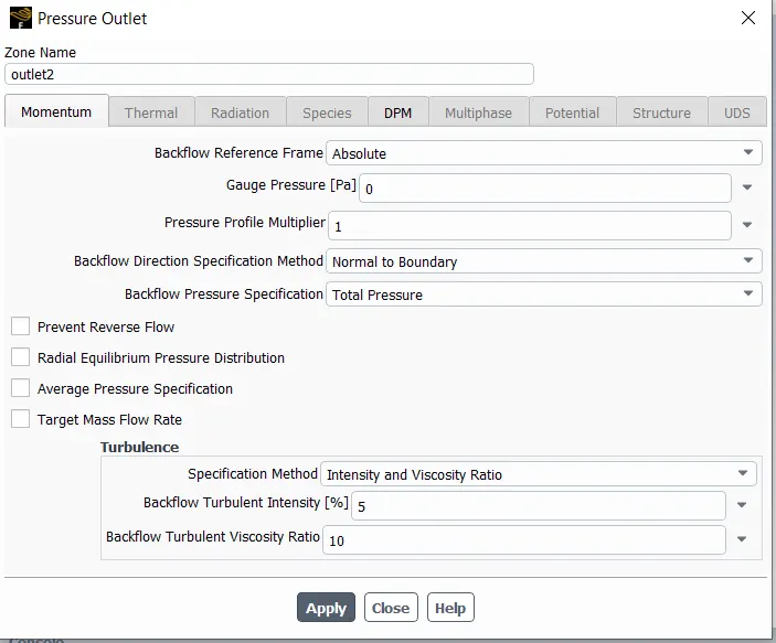
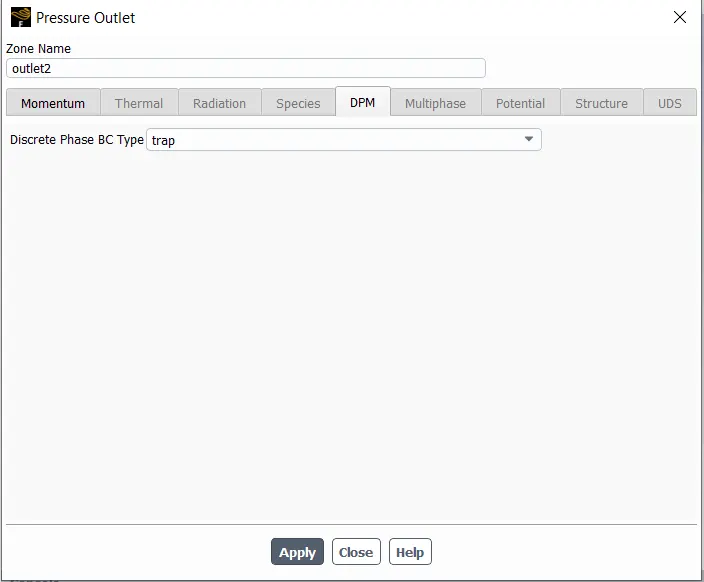
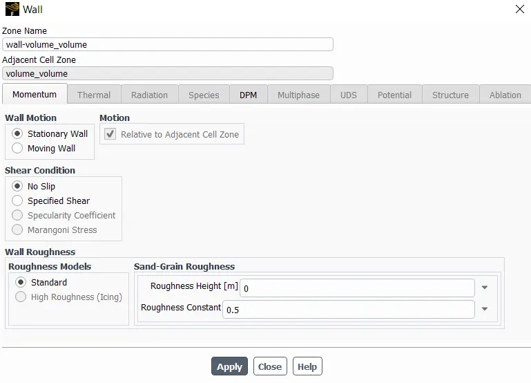
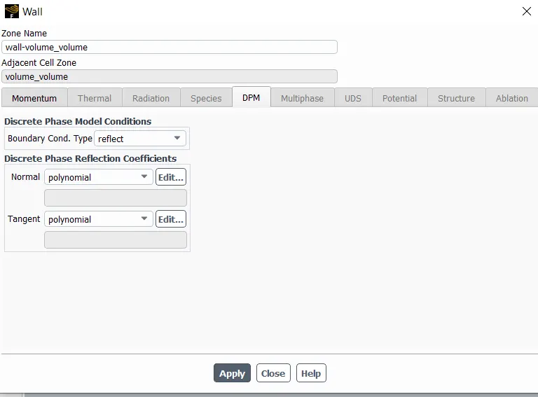
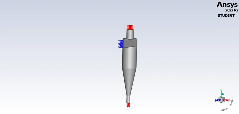
Boundary conditions:
Inlet and wall:- Reflect
Outlet(Top):- Escape
Outlet(Bottom/dustbin) - Trap
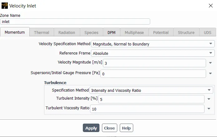
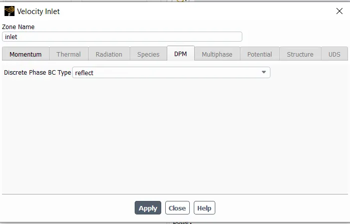
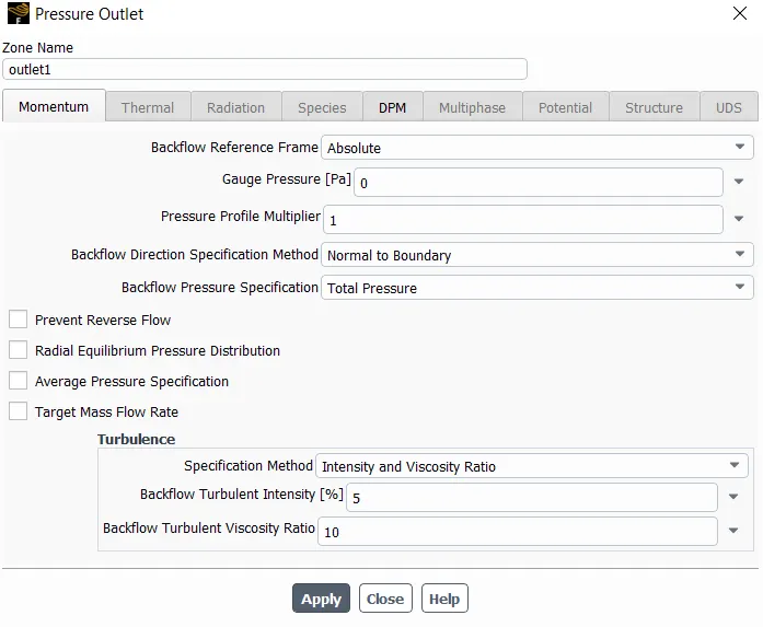
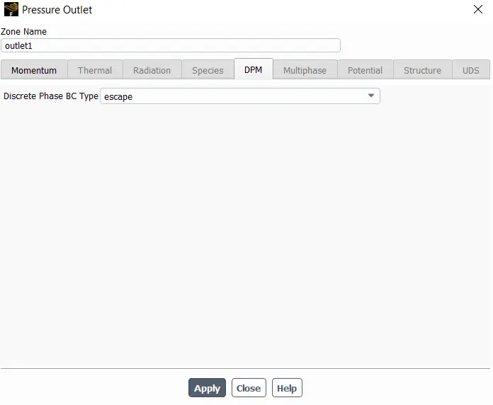
Set up solution method:
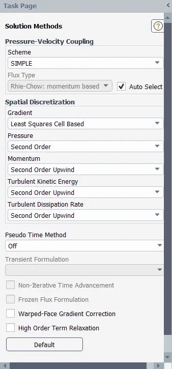
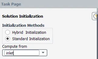
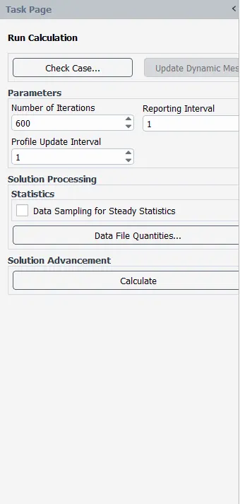
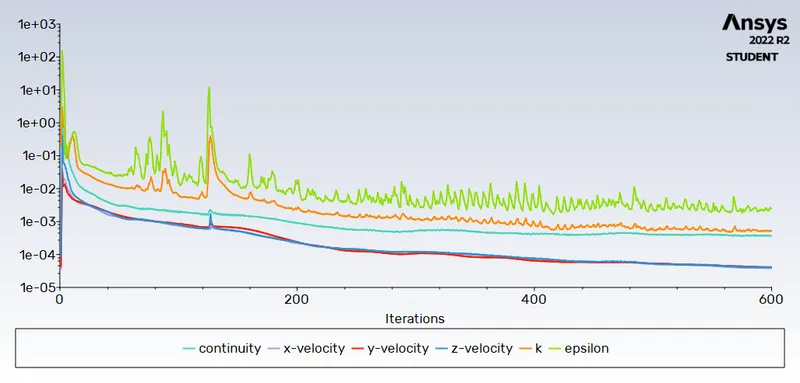
Standard intialization and compute from inlet for 600 iteration:
- Results:
Residuals:
Particle Tracks:
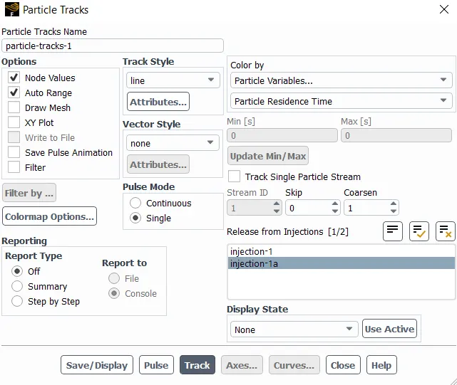
DPM Iteration ....
number tracked = 91, escaped = 30, trapped = 61
Separation efficiency of the cyclone separator:
The separation efficiency of the cyclone separator is calculated as,
Seperation efficiency=(trapped particle/tracked particle)*100=(61/91)*100=67.03%
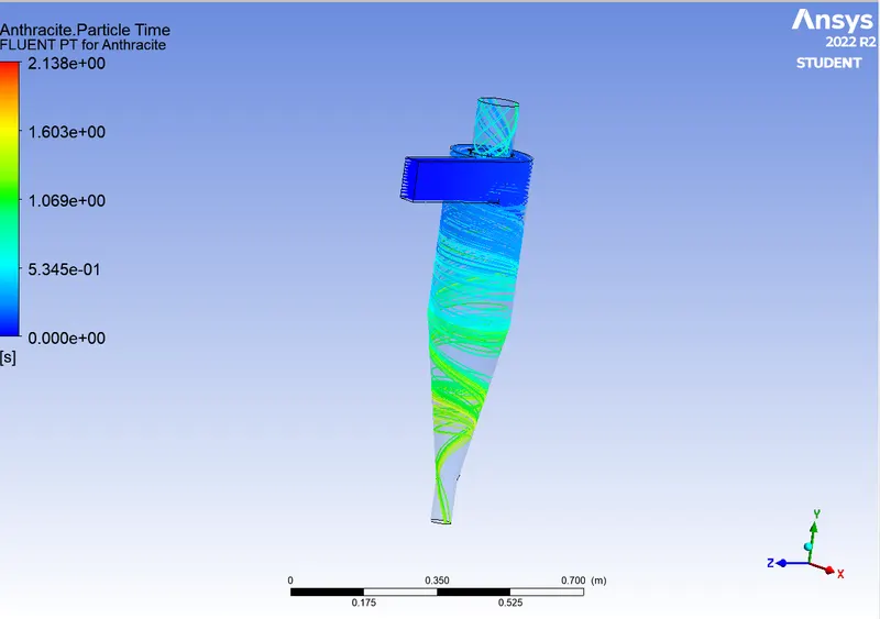
Anthracite Partcle time plot:
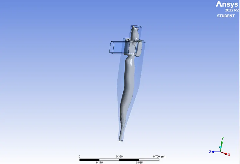
Vortex core region plot:
Pressure plot:
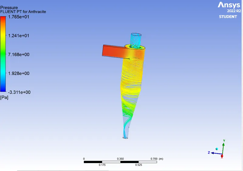
- Particle diameter of 3 µm, while maintaining the particle velocity at 3 m/s:
Only change in injection properties (particle diameter)
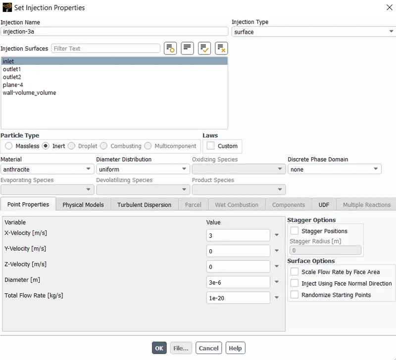
Results:
Residuals:
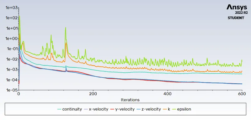
DPM Iteration ....
number tracked = 91, escaped = 29, trapped = 62
Seperation efficiency=(trapped particle/tracked particle)*100=(62/91)*100=68.13%
Anthracite Partcle time plot:
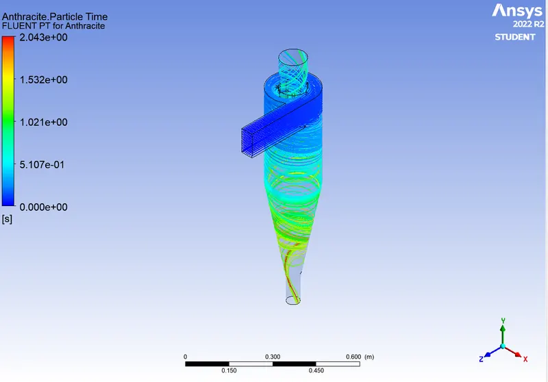
Vortex core region plot:
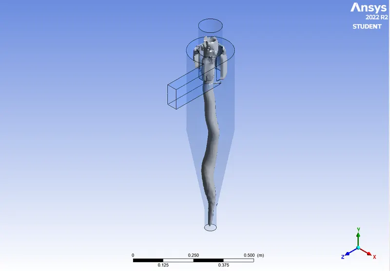
Pressure plot:
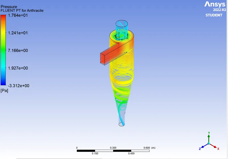
- Particle diameter of 5 µm, while maintaining the particle velocity at 3 m/s:
Only change in injection properties (particle diameter)
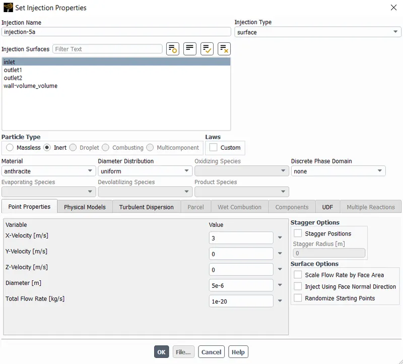
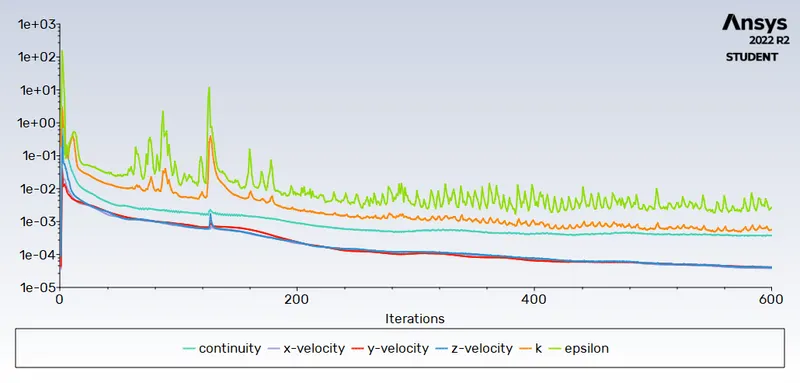
Results:
Residuals:
DPM Iteration ....
number tracked = 91, escaped = 32, trapped = 59
Seperation efficiency=(trapped particle/tracked particle)*100=(59/91)*100=64.83%
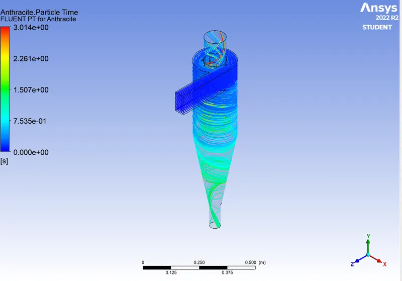
Anthracite Partcle time plot:
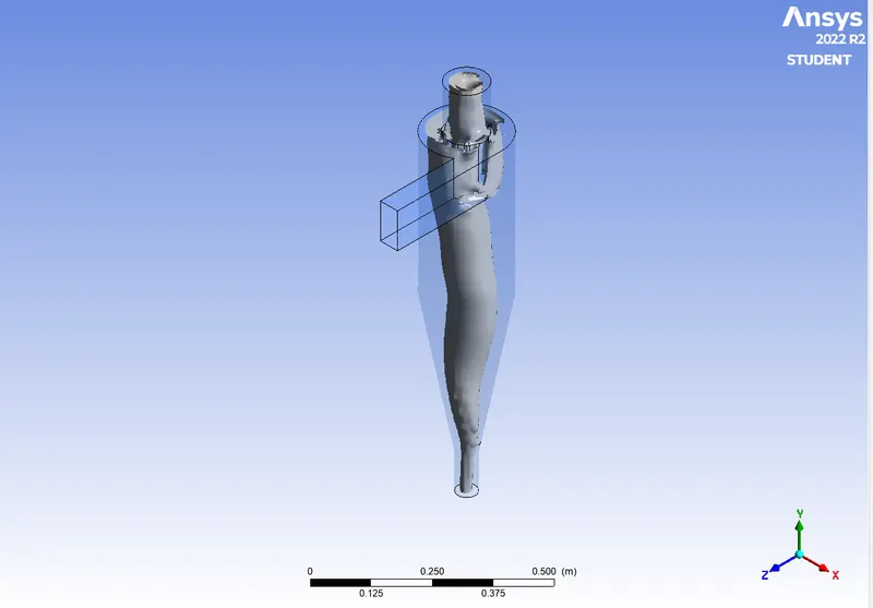
Vortex core region plot:
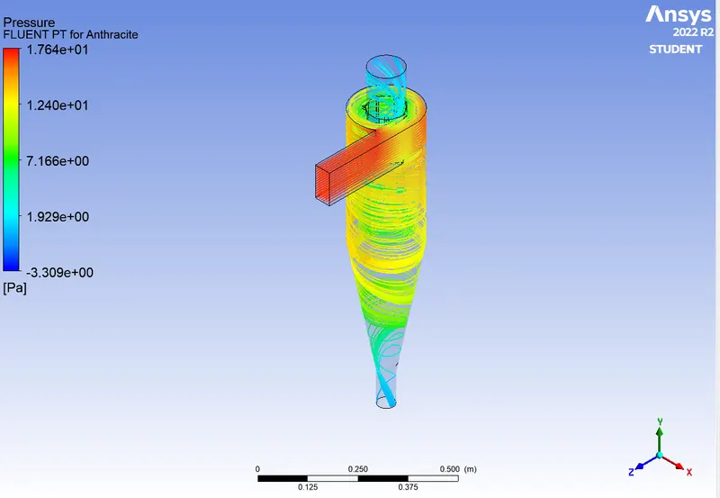
Pressure plot:
CASE 2 :Performing analysis on the given cyclone separator model by varying the particle velocity from 1 m/sec to 5 m/sec.
- Particle diameter of 5 µm, while maintaining the particle velocity at 1 m/s:
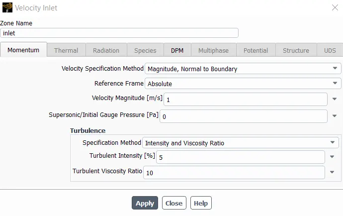
Results:
Residuals:
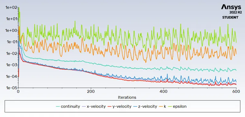
DPM Iteration ....
number tracked = 91, escaped = 23, trapped = 68
Seperation efficiency=(trapped particle/tracked particle)*100=(68/91)*100=70.10%
pressure drop :
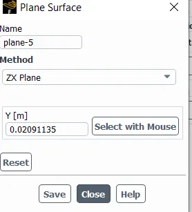
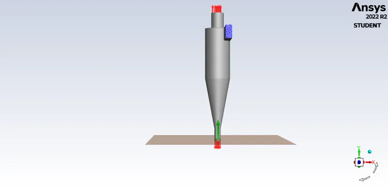
Area-Weighted Average [Pa]
-------------------------------- -------------------
plane-5 0.018494437
Area-Weighted Average [Pa]
-------------------------------- -------------------
inlet 1.6750905
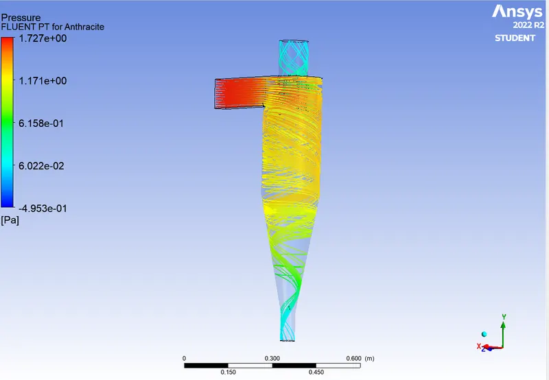
Pressure drop: 1.66 Pa
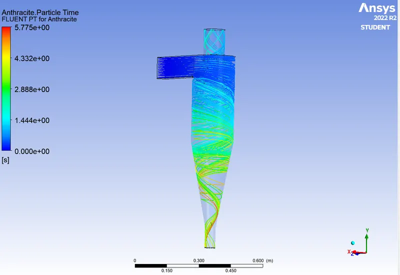
Anthracite Partcle time plot:
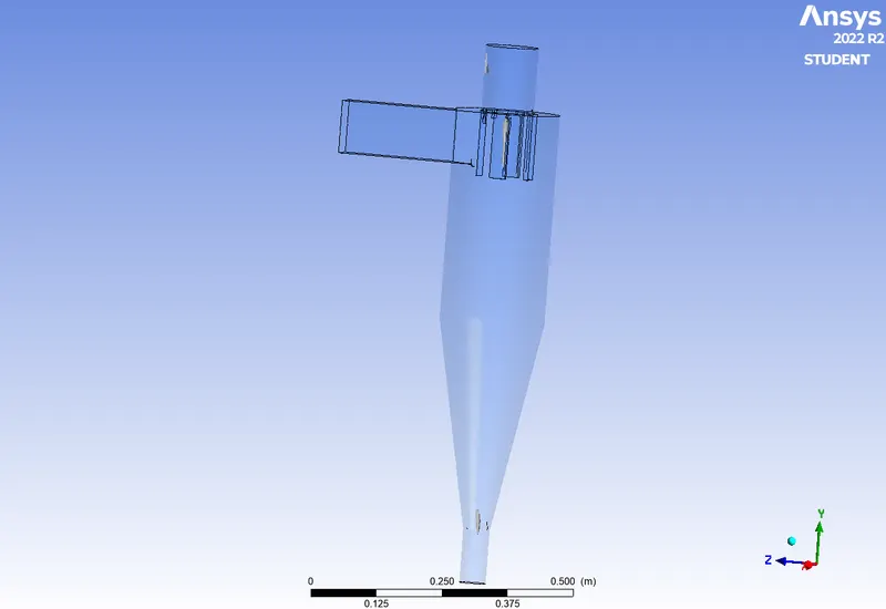
Vortex core region plot:
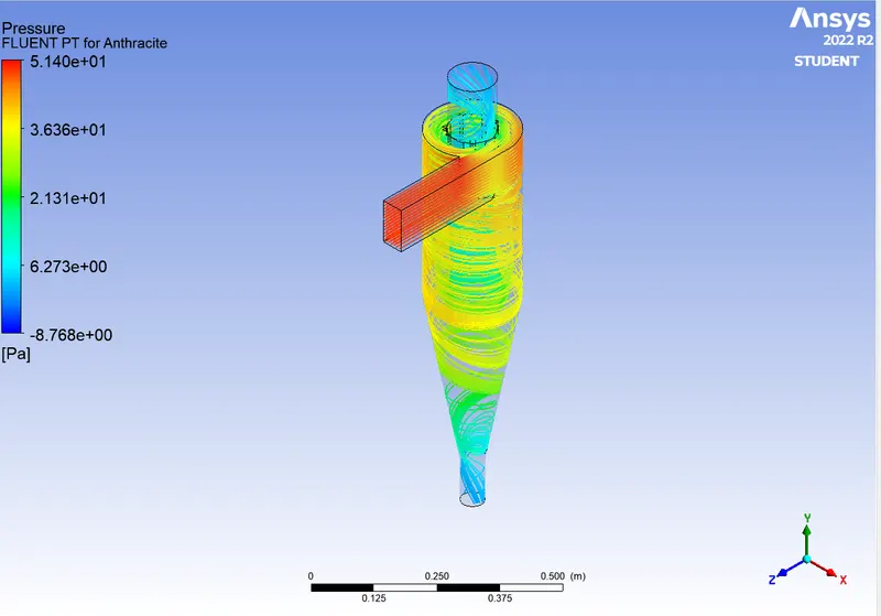
Pressure plot:
- Particle diameter of 5 µm, while maintaining the particle velocity at 3 m/s:
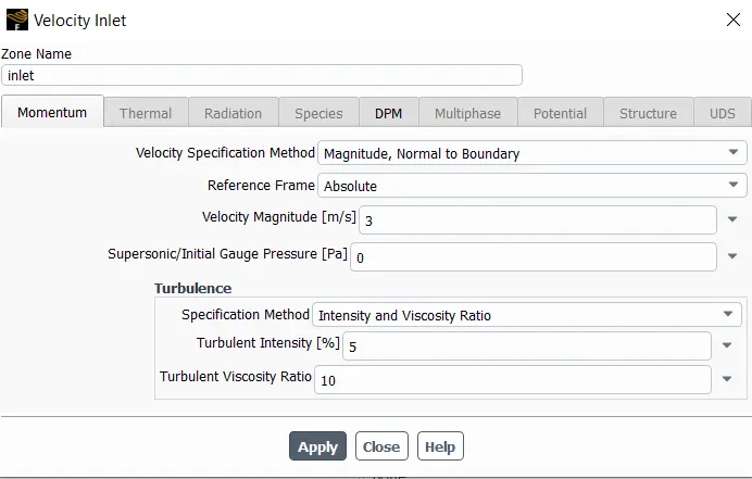
Results:
Residuals:
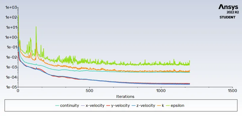
DPM Iteration ....
number tracked = 91, escaped = 35, trapped = 56
Seperation efficiency=(trapped particle/tracked particle)*100=(56/91)*100=61.54%
pressure drop :
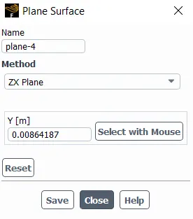
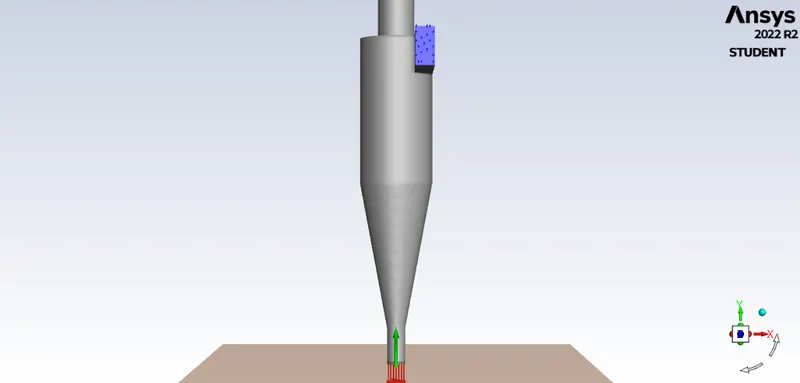
Area-Weighted Average [Pa]
-------------------------------- -------------------
plane-4 0.20057185
Area-Weighted Average [Pa]
-------------------------------- -------------------
inlet 17.329362
Pressure drop: 17.13 Pa
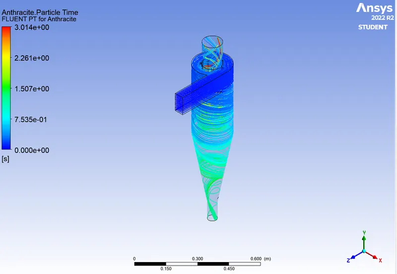
Anthracite Partcle time plot:
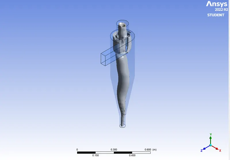
Vortex core region plot:
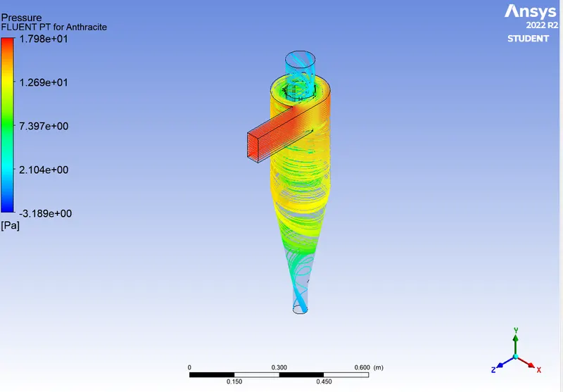
Pressure plot:
- Particle diameter of 5 µm, while maintaining the particle velocity at 5 m/s:
Results:
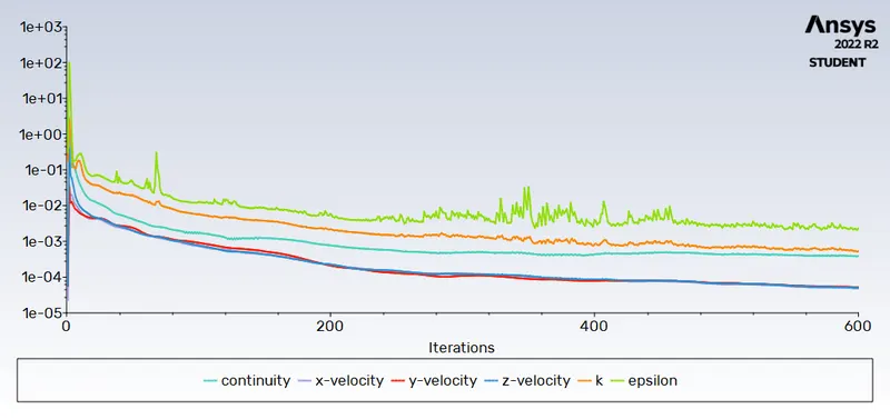
Residuals:
DPM Iteration ....
number tracked = 91, escaped = 39, trapped = 52
Seperation efficiency=(trapped particle/tracked particle)*100=(52/91)*100=57.14%
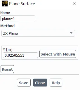
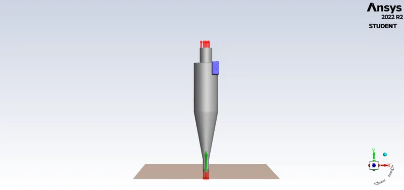
pressure drop :
Area-Weighted Average [Pa]
-------------------------------- -------------------
plane-4 0.84495525
Area-Weighted Average [Pa]
-------------------------------- -------------------
inlet 49.273294
Pressure drop: 48.43 Pa
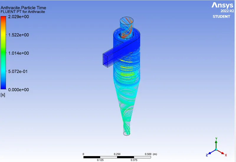
Anthracite Partcle time plot:
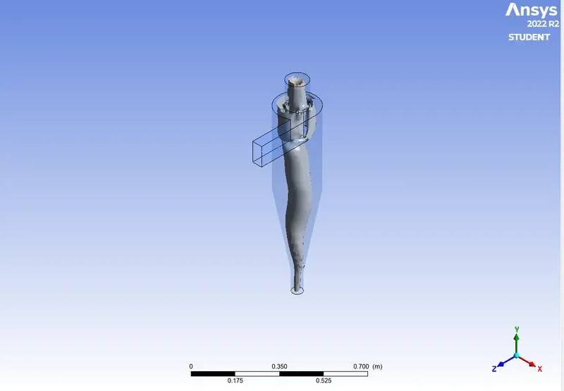
Vortex core region plot:
Pressure plot:
| Cases | Separation efficiency |
| particle diameter 1 μm , velocity 3m/sec | 67.03% |
| particle diameter 3 μm , velocity 3m/sec | 68.13% |
| particle diameter 5 μm , velocity 3m/sec | 64.83% |
| velocity 1m/sec, particle diameter 5 μm | 70.10% |
| velocity 3m/sec, particle diameter 5 μm | 61.54% |
| velocity 5m/sec, particle diameter 5 μm | 57.14% |
Conclusions:
The simulation has been successfully run for both the cases and their sub-cases and their respective plots and contours have been obtained as shown. The effects due to the variation of particle diameter size as well as the particle velocity, on the separation efficiency have been successfully studied and compared under given boundary conditions.
It can be concluded that in the first case study, for varying particle size, Seperation efficiency increases with increase in particle size but for 5 μm particle size seperation efficiency decreases slightly and in the second case study ,for varying velocity,Seperation efficiency decreases with increase in velocity.
References: