Week 8 - Simulating Cyclone separator with Discrete Phase Modelling
Aim:
To perform analysis on cyclone separator and calculate the separation efficiency and pressure drop.
Objective:
- To write a few words about any four empirical models used to calculate the cyclone separator efficiency.
- To perform an analysis on a given cyclone separator model by varying the particle diameter from 1 μm to 5 μm and calculate the separation efficiency in each case. Discuss the results. [Use both the velocity's as 3m/sec.]
- To perform an analysis on a given cyclone separator model by varying the particle velocity from 1 m/sec to 5 m/sec and calculate the separation efficiency and pressure drop in each case. Discuss the results. [Use particle diameter size as 5 μm for all cases & keep flow velocity same as particle velocity].
Cyclone Separator:
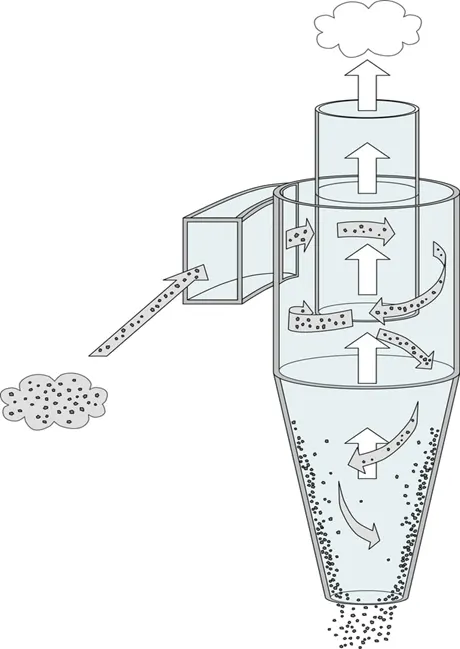
The solids to be separated are suspended in a stream of gas (usually air). Such a feed is introduced tangentially at a very high velocity so that rotary movement takes place within the vessel. The centrifugal force and vortexing throw the solids to the walls. As the speed of air diminishes, the particles fall to the conical base and are discharged through the solid outlet. The fluid (air) can escape from the central outlet at the top.
Cyclone separator uses:
- It is used to separate the solids from gases.
- It is also used for the size separation of solids in liquids.
- It is used for separating the heavy or coarse fraction from fine dust.
Cyclone Separator Image:
Step 1: Geometry
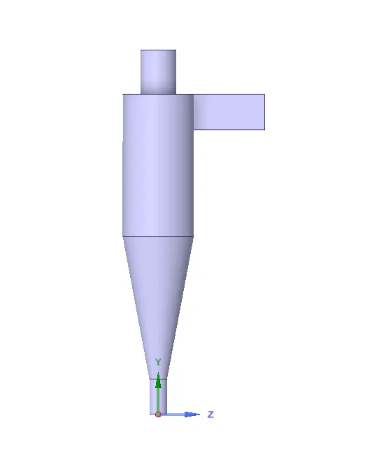
In this challenge the first step is we have to do geometry process, so we have to import the given geometry and then go to prepare > volume extract > select the fluid volume > give ok and then disable the upper surface and give the suppress for physics option. Once we complete the geometry process after that we have to move next meshing option.
Step 2: Meshing
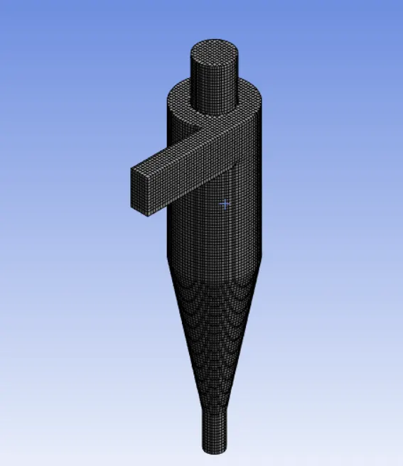
In this challenge the second step is meshing process, go to mesh option right click > inset > methods > select body > apply > 5mm > Cartesian method > update. And then give named selection option, the names are inlet, escape, trap. Once we complete the meshing option after that we have to move next set-up option.
Step 3: Set-up
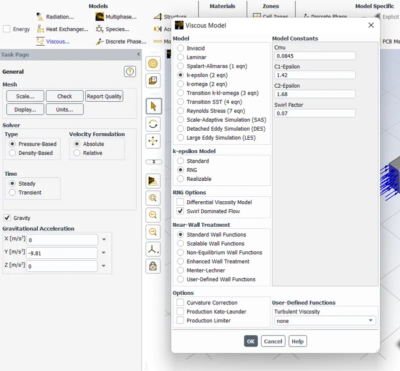
In this challenge the third process is set-up process. We have to select Type: Pressure based, Velocity Formulation: Absolute, Time: Steady, Gravity on in Y axis input -9.81 m/s^2. Go to physics tab, we have to click on viscous and select k-epsilon > RNG > Swirl dominating flow as well.
Go to discrete phase model > interaction with continues phase > injections > create > injection type surface > inlet > velocity 3m/s > particle size > 3micrometer > ok > close.
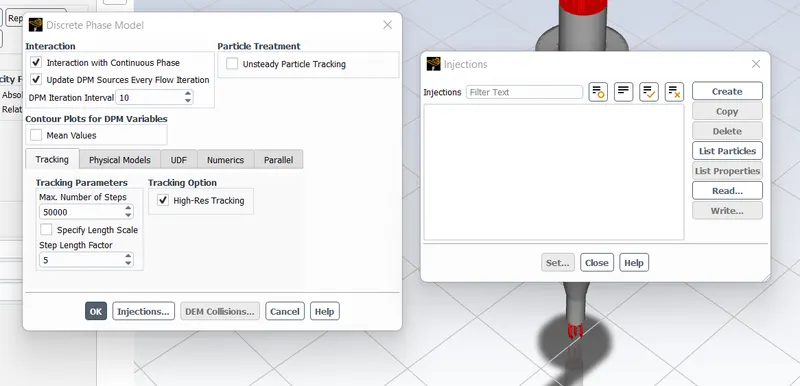
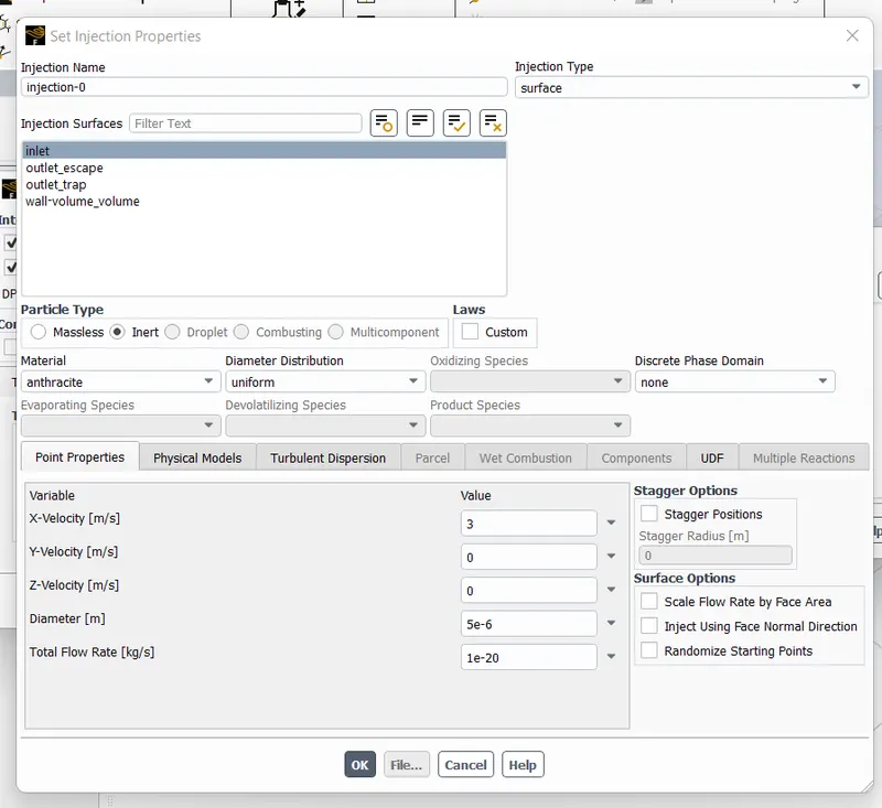
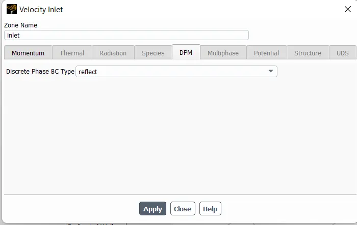
Next step is we should give boundary conditions > inlet > velocity 3m/s > DPM > reflect > ok, next click on outlet escape > edit > DPM > escape > apply, outlet trap > edit > DPM > trap > apply. Discrete phase set-up process is almost same for 5 cases only we can change the velocity and particle size.
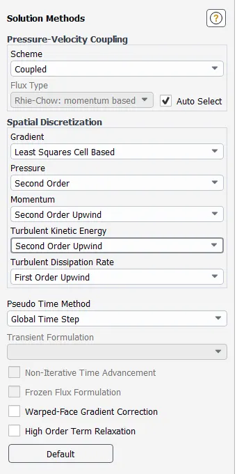
Go to methods > choose second order upwind options, give Initialize. And then run the simulation once complete the simulation we have to save the particle data go to file > export > particle data size > select injection > browse > save particle size data. Go to report > surface integral > take the value of pressure drop.
Step 4: Solution
In this challenge some processes are already done by set-up process. So we have to move next result option.
Step 5: Result
First open the result tab and then we have to go file > import > import particle data > select file > ok. Go to animation option create animation file and save it. Go to location option create plane and then find the velocity and pressure. This process is same for remaining four cases.
Results contours:
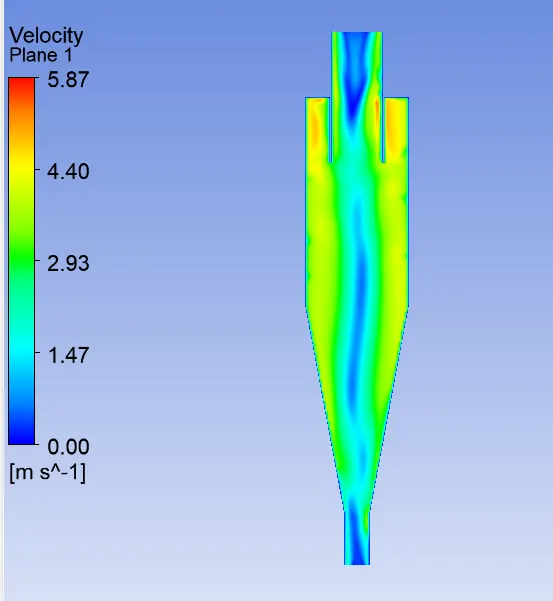
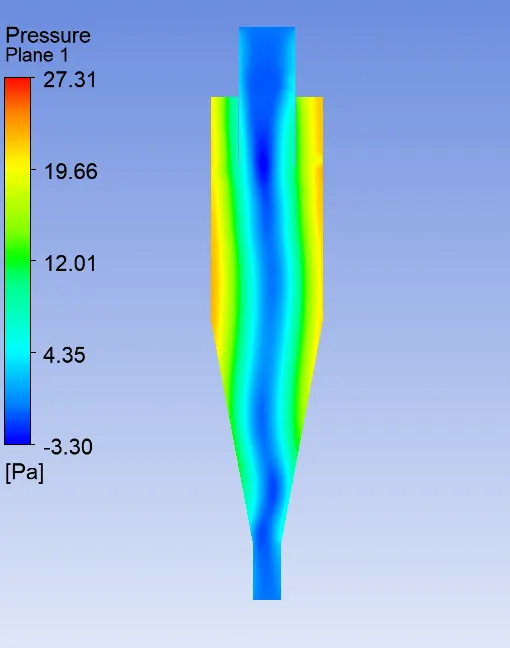
Case 1 Pressure and velocity contour image

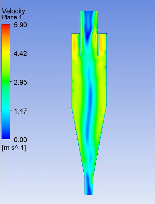
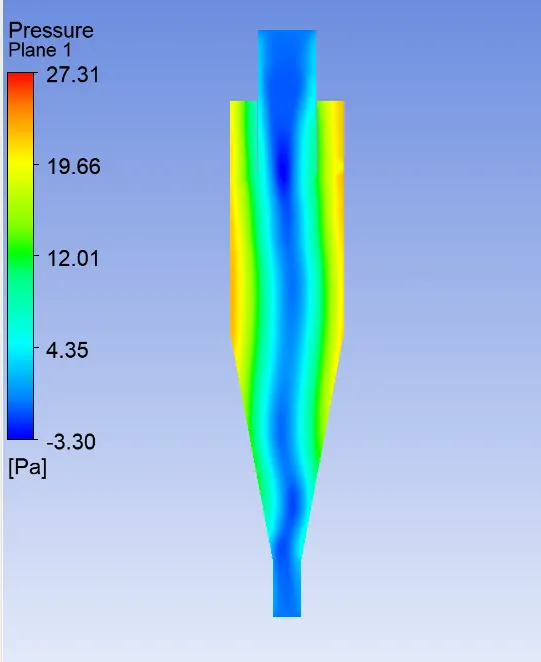
Case 2 Pressure and velocity contour image:
Case 3 Pressure and velocity contour image:
Case 4 Pressure and velocity contour image:
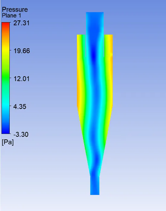

Case 5 Pressure and velocity contour image:
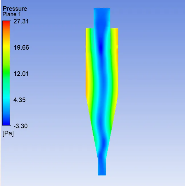
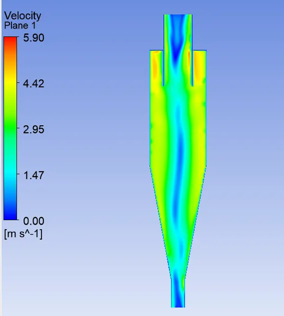
Anthracite particle time animation Gif case 1:
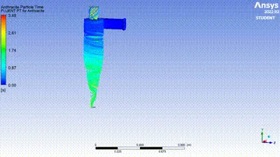
Anthracite particle time animation Gif case 2:
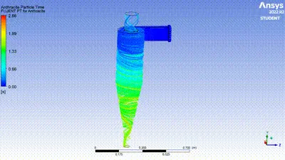
Anthracite particle time animation Gif case 3:
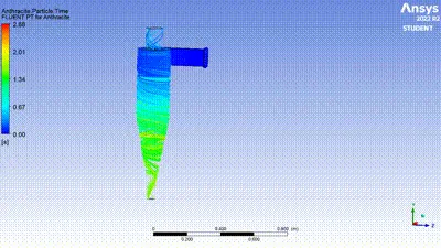
Anthracite particle time animation Gif case 4:
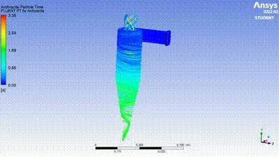
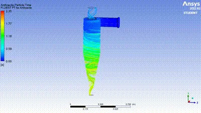
Anthracite particle time animation Gif case 5:
Conclusion:
Finally, we completed all the five cases and we found the five cases particle track, escape, trap, efficiency (trap/track) and pressure drop (between inlet particle and escape particle). Below I mentioned all the following information.
case inlet particle particle Particle Particle Particle Efficiency (%) Pressure Difference(Pa)
velocity size Tracked Escaped Traped Incomplete
1 5 3 378 32 342 4 90.4 23.21
2 1 3 378 79 299 - 79.1 23.21
3 1 5 378 20 358 - 95.4 22
4 5 5 378 120 258 - 68.2 22.31
5 3 3 378 73 305 - 80.6 22.75
Inferences:
In this challenge we studied the efficiency by using track, trap, and particle incomplete. The efficiency is almost near by 90 %. Case 1 only converged in 219 iterations. Cyclone separator is basically used to separate the solids from gases and also used for the size separation of solids in liquids. In this challenge we found the pressure difference between inlet particle and escape particles.
References:
https://www.researchgate.net/publication/312160127_Design_and_fabrication_of_cyclone_separator
https://www.sciencedirect.com/topics/engineering/cyclone-separator
https://www.sciencedirect.com/science/article/pii/S0307904X06000291
https://www.researchgate.net/topic/Cyclone-Separator/publications