Week 8 - Simulating Cyclone separator with Discrete Phase Modelling
Aim:- To perform analysis on cyclone separator and calculate the separation efficiency and pressure drop.
Theory:- Cyclone Seperator is devices which seperates the foregin(dirt) particles like dust, unwanted particles from the fluid this study simulation run in this challenge, In this challenge we taken the seperate 1micro meter, 3micro meter and 5micro meter foreign particle and injected into the seperate fluid with velocity 3m/s through inlet and finds the seperation efficiency. Then we taken the 5micro particle as constant and varying the velocity 1m/s, 3m/s and 5m/s running the simulation And finally we conclude which case is giving good efficiency
There are number of emprical model were there to calculated seperation efficiency, Below are the few among us:
- Iozia and Leith Model
Procedure to run the simulation of Cyclone seperation:-
- First we opening the Ansys workbench and drag and drop the flow fluent solver into the project schematic and by right click on the geometry in the mouse we visible the new space claim then we open the new space claim and importing the geometry model into the space claim by drag the cyclone seperation model file into the sketch window
- Then we extract the volume, How to extract the volume is shown in image2 Then we close the new space claim window and opened mesh window.
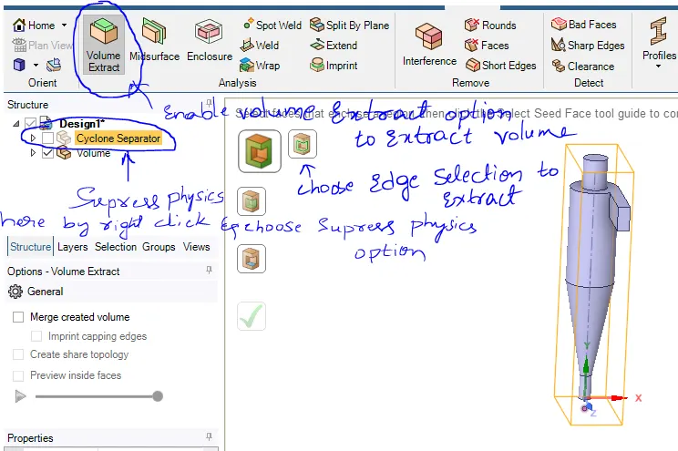
- Then in mesh window we insert the cartesion method and giving the 5mm target length we mesh to the model and assign the name selection to inlet, outlet escape and outlet trap and this meshed model is shown in image3
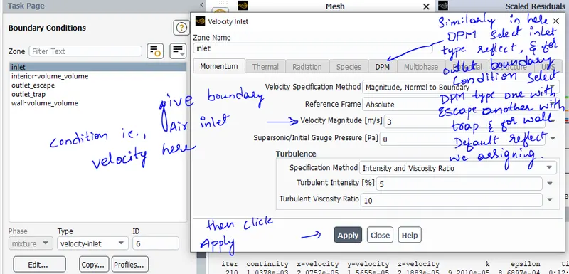
- Next we close the mesh window and opened the setup window there we set up the viscous model, gravity value, discrete phase and bondary condition
- This viscous model and gravity set up is shown in image4(a), Discrete phase set up is shown in image4(b), and boundary condition set up in image4(c)
- Then we intialize the problem and run the 350 iteration calculation but value is converging below 350 iteration
- Then we take out the results of scaled residual, pressure drop at outlet escape, and calculating the seperation efficiency using formula, This formula and calculations are calculated below
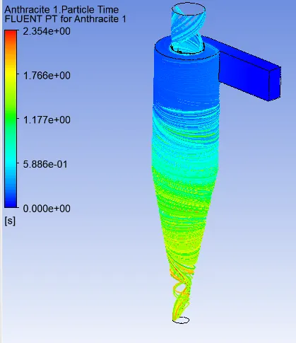
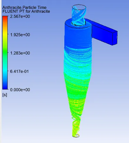
- Also we taking out the antracite particle time contour plot in post processing but before going to post processing, First we export the particle history data from solving to export first we click on the file then there is option export we click on that and we see the export particle history data then we click on that and finally we save as the data in fluent location by selecting injection, clicking on browser and click on the write option
- This finall results is upload in tabular column below and also attached in below image5, image6, image7
- So by this we run the simulation from five different cases
Calculation:-
1. seperation efficiency formula
efficiency =(Particle trapped / particle tracked)
Where, Particle tracked value= depends on how many row and column structural mesh providing at inlet
particle trapped value= This value we get from the simulation result
2. pressure drop formula
delta p = p1-p2
where, p1= pressure at inlet
p2= pressure at outlet-escape
Calculation of seperation efficiency and prssure drop
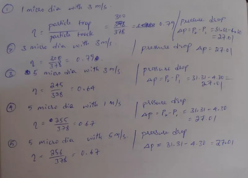
Result on tabular column:
| Antracite particle diameter | Particle injected velocity | Seperation efficiency | pressure drop at outlet-escape |
| 1. 1micro meter | 3meter per second | 79% | 27.01 |
| 2. 3 micro meter | 3meter per second | 79% | 27.01 |
| 3. 5micro meter | 3meter per second | 64% | 27.01 |
| 4. 5micro meter | 1meter per second | 67% | 27.01 |
| 5. 5micro meter | 5meter per second | 67% | 27.01 |
Geometery clean up:
Image1: Given model
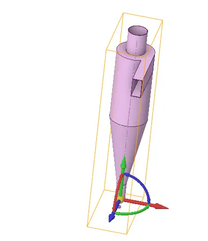
Image2: Final model with volume extracted
Meshing the model:
Image3: Model is meshed with cartesian method and assign name selection
Setting the set up:
Image4(a): Viscous model and gravity set up
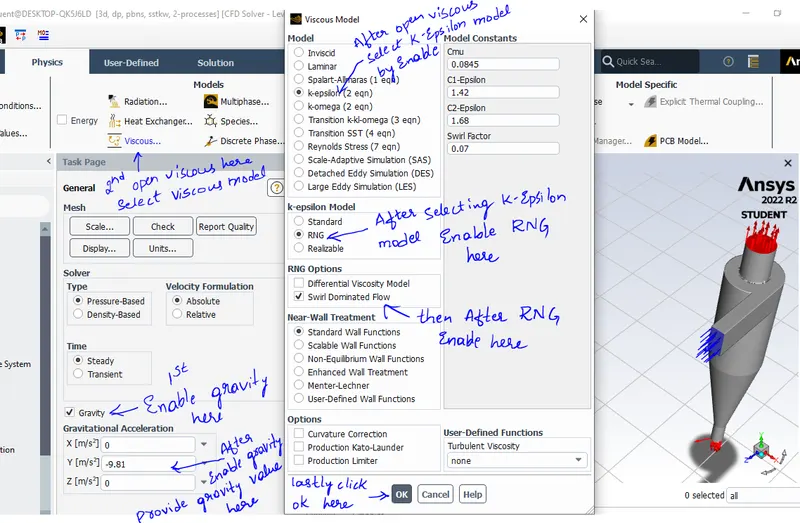
Image4(b): Discrete phase set up
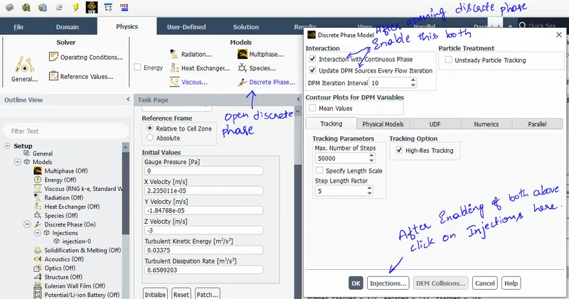
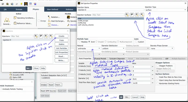
Image4(c): boundary condition set up
Result are attached in images of five cases:
case1: 1micro meter dia of antracite particle injecting to fluid through inlet with 3m/s velocity:
Image5: Last iteration result on console screen and prssure drop result on console
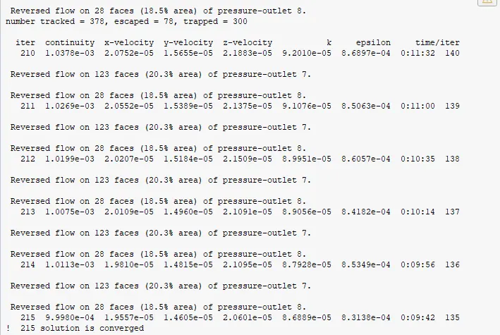
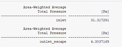
Image6: Scaled residual plot
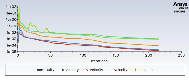
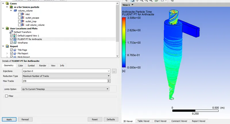
Image7: Antracite particle time in Cylone seperator contour plot
case2: 3micro meter dia of antracite particle injecting to fluid through inlet with 3m/s velocity:
Image5: Last iteration result on console screen and prssure drop result on console
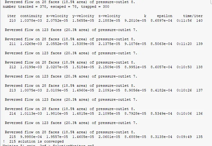
Image6: Scaled residual plot
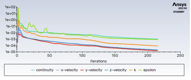
Image7: Antracite particle time in Cylone seperator contour plot
case3: 5micro meter dia of antracite particle injecting to fluid through inlet with 3m/s velocity:
Image5: Last iteration result on console screen and prssure drop result on console
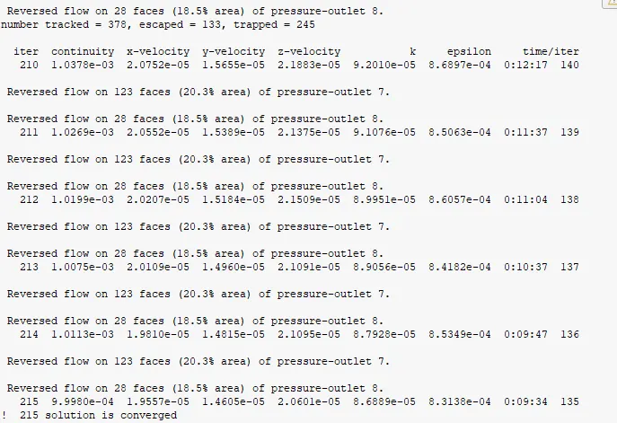
Image6: Scaled residual plot
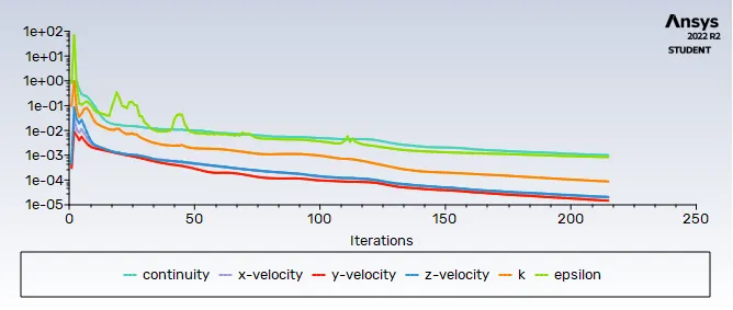
Image7: Antracite particle time in Cylone seperator contour plot
case4: 5micro meter dia of antracite particle injecting to fluid through inlet with 1m/s velocity:
Image5: Last iteration result on console screen and prssure drop result on console
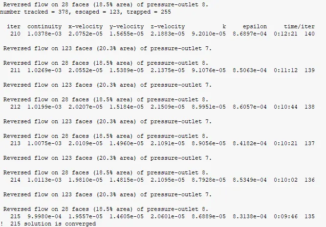
Image6: Scaled residual plot
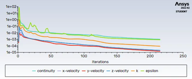
Image7: Antracite particle time in Cylone seperator contour plot
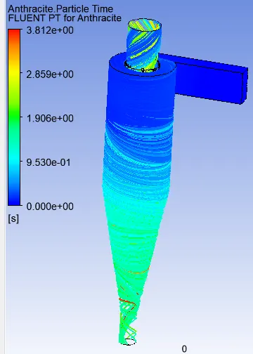
case5: 5micro meter dia of antracite particle injecting to fluid through inlet with 5m/s velocity:
Image5: Last iteration result on console screen and prssure drop result on console
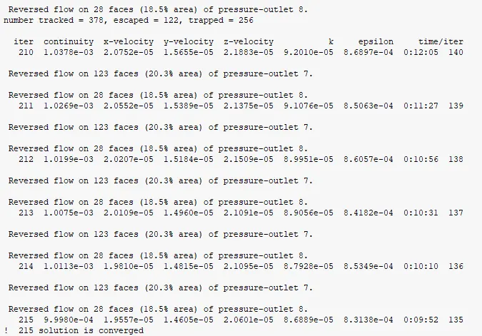
Image6: Scaled residual plot
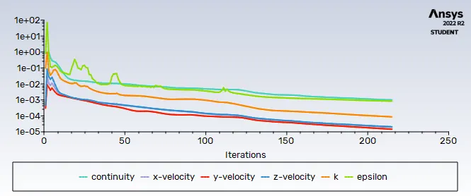
Image7: Antracite particle time in Cylone seperator contour plot
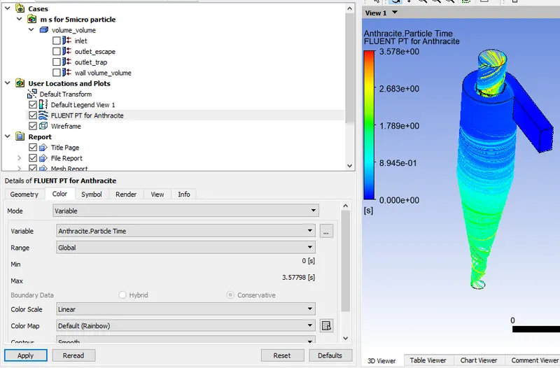
Final report definition:
- By running simulation and calculation of seperation efficiency above we conclude the cyclone seperation devies gives good result for finer micro meter dia particle
Conlusion: By the above procedure successfully Simulating the Cyclone separator with Discrete Phase Modelling