Week 2 Challenge : Surface meshing on a Pressure valve
Aim : For the given model, check for the geometrical errors and perform Topology cleanup accordingly. Set three different target lengths as three different cases and mesh the model
Procedure of meshing given model are:
- firstly we checking the geometric check there we looking over the single con, triple con, penetration of two surfaces, if there what all is not required we deleting step by step
- first step we are perfectly patching the the crack which is present over the component this cracks is identified by single cons
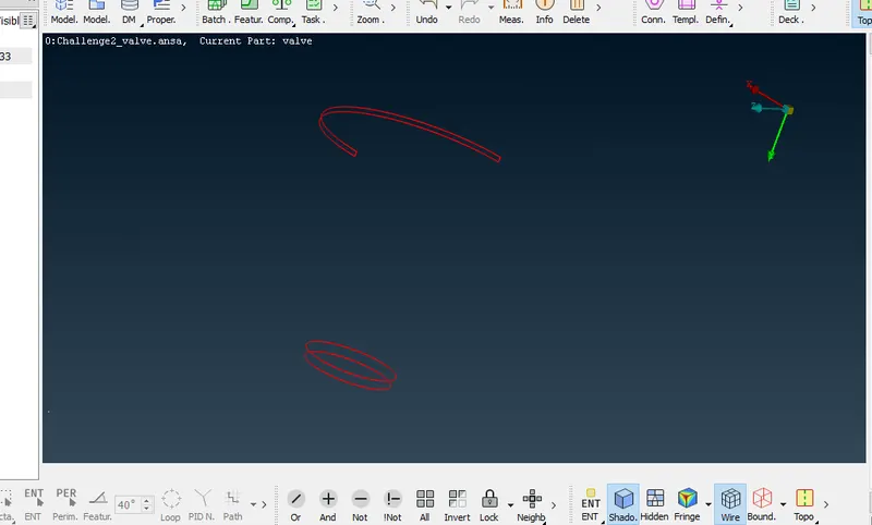
- this cons can be visible by turn off triple con, double con, option and turn on wire frame option which there bottom of the toolbar
- So by knowing single con we are patching the crack present over the component by using new option which is there in the face option in the right of the screen
- In the new option there is option there like existing surface, planar, cons, fitted like this this helps to patch the cracks
- existing surface is patch the crack by clicking on the cons, clicking middle of the mouse and then clicking on the existing surface so the crack fill as like as existing surface
- fitted and con option is patching the crack by selecting cons, click middle mouse then surface form and also there it shows alternate option which ever we want the surface we choose by there
- so after patching all cracks to mesh the component we are making the component that the entire surface is to close
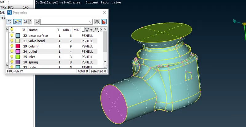
- so that we are closing the inlet and outlet component
- after all this we are giving the pid for different different component by using property manager which present in the top toolbar like pid for spring, pid for column, pid for body, pid for valve head, pid for inlet and outlet
- Pid is used because to mesh the different different component different different target length it usefull and also it gives different different color for different different component
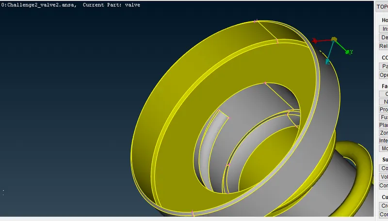
- after giving pid there the spring and column intersect each other it is solved by turn on intersect option, clicking two intersect surface and clicking middle mouse
- Then last we are meshing the component by giving target length which perimeter of 5mm, macron 5mm, and average mesh quantity 5mm and also we giving mesh element type tria for the body, inlet, outlet component
- similarly for column, valve head component setting taget length 3mm and giving tia element we are meshing
- for we are giving the 1mm target length
note:
- we should check the surface before meshing because surface should not be there bigger size than target length if there it not mesh proper so kindly look over that
learning outcomes :
- firstly we cleaning the suface by topo cleaning using different different tool face option, hotpoints option cons option, etc..,
- after topo cleaning we meshing the 2d surface using different different tool like hot points, perimeter, mesh generation, etc..,
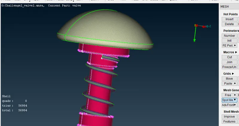
Result is attached in the image below:
1.First view is first step that the component pattched the crack and closed the surface which all opened and given a pid for different different component:
2.view that wire frame mode option that helps to find the single con:
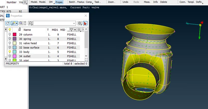
3.view shows the isolated part of the body:
4.View shows the intersection part between the column and spring avoided:
5.view shows that good suface meshing formed in column and spring by giving 1mm target length:
link of the model is:https://drive.google.com/file/d/1WV8nPgyZUPGRTw4rI7z8KRUwHfwOTcqk/view?usp=sharing