Week 8 - Simulating Cyclone separator with Discrete Phase Modelling
Aim: To simulate the flow through the cyclone separator and find its efficiency for varied velocity and particle sizes.
Theory:
- Cyclones are devices that employ a centrifugal force generated by a spinning gas stream to separate particles from the carrier gas. Their simple design, low capital cost, and nearly maintenance-free operation make them ideal for use as pre-cleaners for more expensive final control devices such as baghouses or electrostatic precipitators.
- Cyclones are particularly well suited for high temperature and pressure conditions because of their rugged design and flexible component materials. Cyclone collection efficiencies can reach 99% for particles bigger than 5 μm, and can be operated at very high dust loading.
- Cyclones are used for the removal of large particles for both air pollution control and process use. Application in extreme conditions includes the removal of coal dust in a power plant and the use as a spray dryer or gasification reactor.
- Engineers are generally interested in two parameters in order to carry out an assessment of the design and performance of a cyclone. These parameters are the collection efficiency of particle and pressure drop through the cyclone.
- An accurate prediction of cyclone efficiency is very important because inaccuracy in the efficiency prediction may result in an inefficient design of the cyclone separator.
- CFD has a great potential to predict the flow field characteristics and particle trajectories inside the cyclone as well as the pressure drop. The complicated swirling turbulent flow in a cyclone places great demands on the numerical techniques and the turbulence models employed in the CFD codes when modeling the cyclone pressure drop.
Empirical Model:
A) Iozia & Leith Model: Iozia and Leith logistic model is a modified version of Barth Model, which is developed based on force balance. The model assumes that a particle carried by the vortex endures the influence of two forces: a centrifugal force, Z and flow resistance W
`eta=1/(1+((dpc)/(dp i))^beta`
Where, dpi= particle diameter
dpc= cut diameter
beta= Expression for slope parameter based on experimental data.
B) Li & Wang Model: The Li and Wang model include particle bounce or re-entrainment and turbulent diffusion at the cyclone wall. A two-dimensional analytical expression of particle distribution in the cyclone is obtained.
The resultant expression of the collection efficiency for particle of any size is given as
`eta=1-e^(-lambdatheta1)`
where, `theta1=2pi*(S+L)/a`
C) Koch & Licht Model: Koch and Licht collection theory recognized the inherently turbulent nature of cyclones and the distribution of gas residence times within the cyclone. Koch and Licht described particle motion in the entry and collection regions with the additional following assumptions:
- The tangential velocity of a particle is equal to the tangential velocity of the gas flow, i.e. there is no slip in the tangential direction between the particle and the gas.
- The tangential velocity is related to the radius of cyclone by uRn = constant.
`eta=1-e^(-2*((G*tau*Q)/D^3*(n+1))^(0.5/(n+1)`
D) Lapple Model: Lapple model was developed based on force balance without considering the flow resistance. Lapple assumed that a particle entering the cyclone is evenly distributed across the inlet opening. The particle that travels from inlet half width to the wall in the cyclone is collected with 50% efficiency.
The efficiency of collection of any size of particle is given by
`eta=1/(1+((dpc)/(dp i))^2`
Where, dpi= particle diameter
dpc= cut diameter
Ansys Simulation Setup:
Geometry:
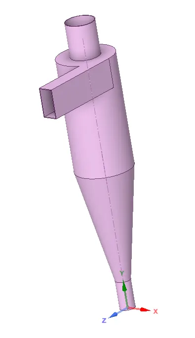
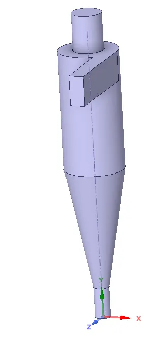
- The Cyclone separator model is imported in space claim and then working fluid volume is extracted
Geometric model: Extracted Volume:
Mesh:
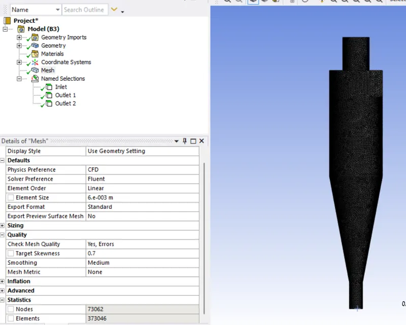
- Generate the mesh for 0.006m element size and skewness to be 0.7
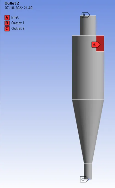
- Select respective face of the model and name them accordingly and update the mesh.
Setup:
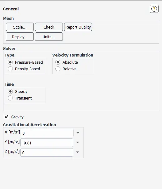
- General setting create pressure based, steady state simulation and enable gravity setting y=-9.81m/s.
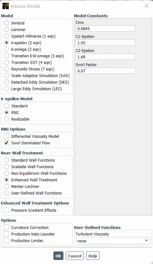
- Turbulence model
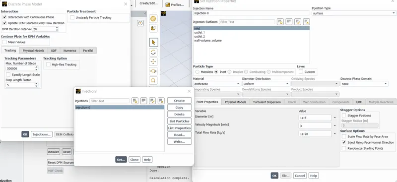
- Discrete Phase Model (DPM): DPM is employed when we want to represent solid particles and gas or liquid or say liquid droplets in a gas or sometimes bubble in a liquid. So, DPM consists of two phases, one is called Continuous phase and another is called the Discrete phase. The continuous phase consists of fluid that is flowing within the fluid volume and the discrete phase consists of smaller particles that are supposed to be interacting with the continuous phase. The Discrete phase can also exchange momentum, mass, and energy with the fluid phase or continuous phase in this case.
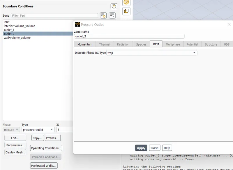
- Boundary Condition
- Inlet – Reflect & 3m/s
- Outlet1 – Escape,
- Outlet2 – Trap
- Wall – Reflect
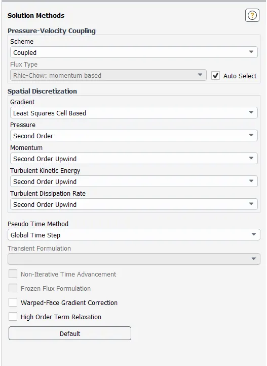
- Solution Scheme
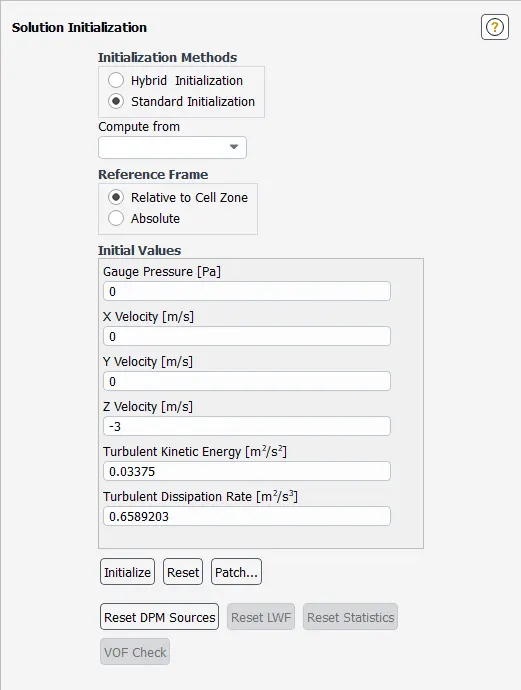
- Solution Initialize
- With respect to the flow velocity and particle diameter change the parameters in the DPM and Inlet boundary condition and leave other setting same.
Case-1 : Varying the particle diameter for inlet velocity of 3m/s
a) Particle diameter: 1e-6m, Velocity: 3m/s
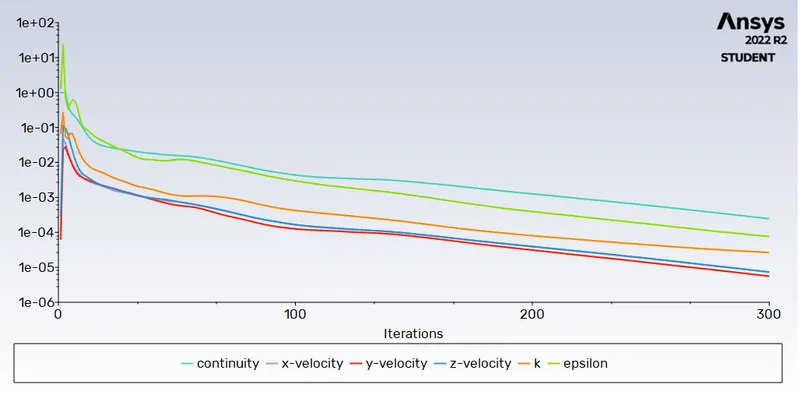
- Residual:
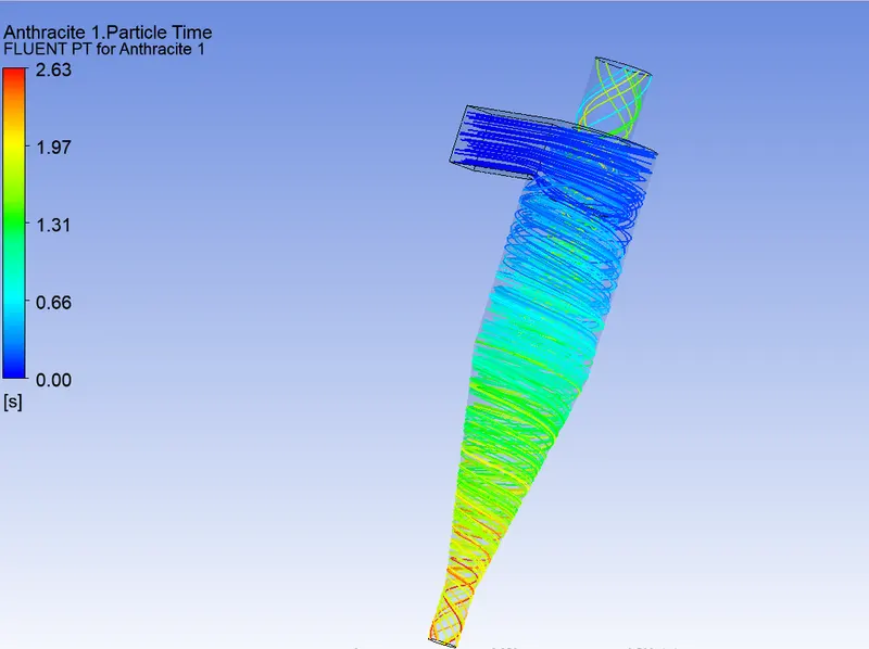
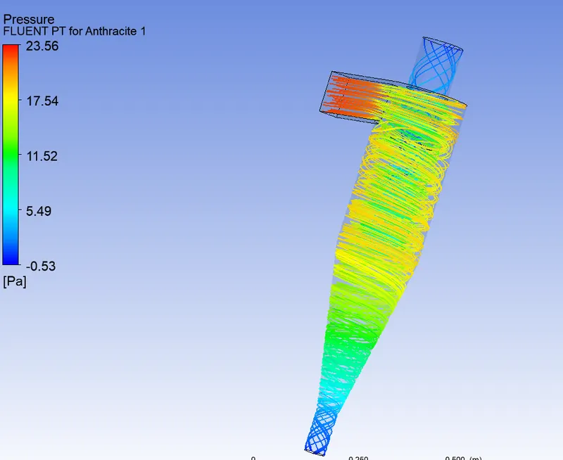
- Particle Flow Time:
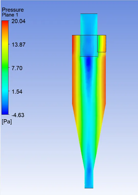
- Pressure Flow:
- Pressure Contour:
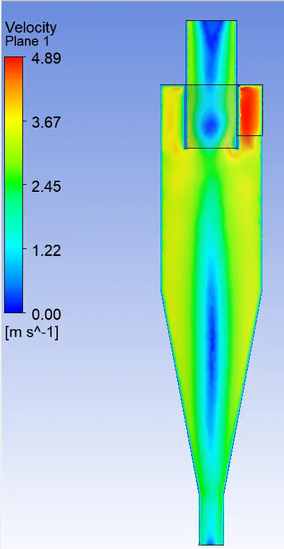
- Velocity Contour:
- Video Link:
https://drive.google.com/file/d/1MBmLdILdKZXq3gOTXSXTKMTK4ekopITd/view?usp=sharing
- Result:

b) Particle diameter: 3e-6m, Velocity: 3m/s
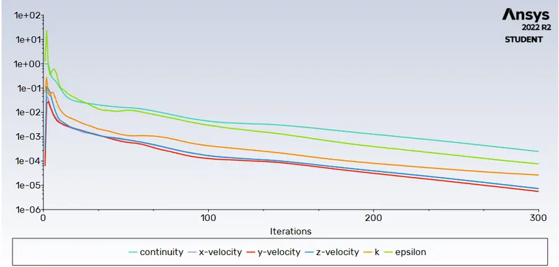
- Residual:
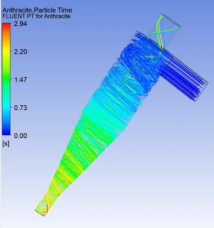
- Particle Flow Time:
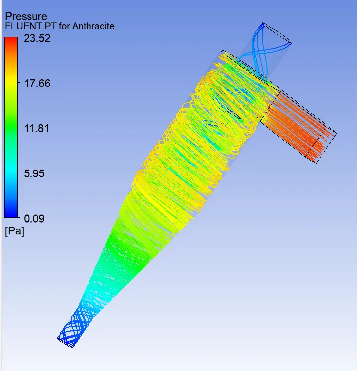
- Pressure Flow:
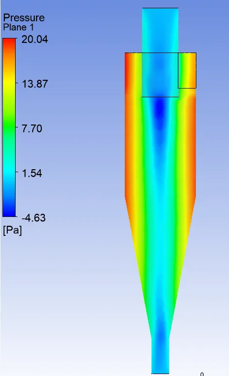
- Pressure Contour:
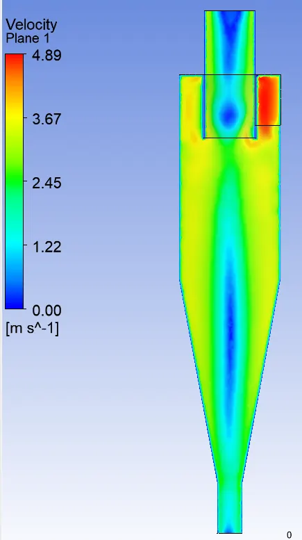
- Velocity Contour:
- Video Link:
https://drive.google.com/file/d/1tXiMuOM9aS9Jv-0uGybbhnVP8ejq782w/view?usp=sharing
- Result:

c) Particle diameter: 5e-6m, Velocity: 3m/s
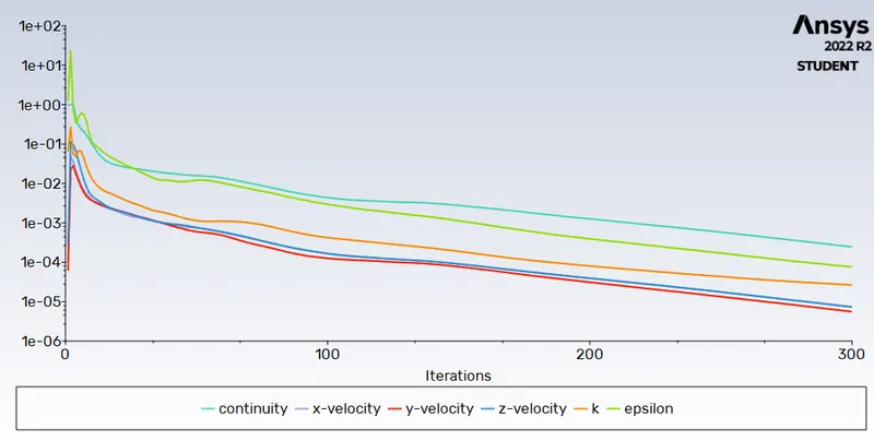
- Residual:
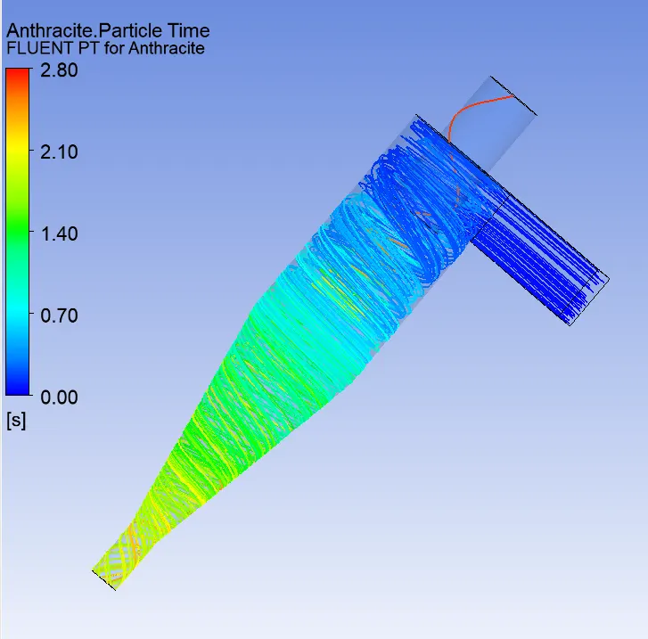
- Particle Flow Time:
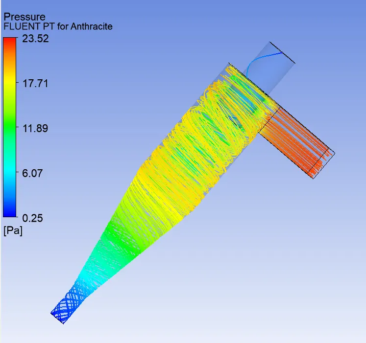
- Pressure Flow:
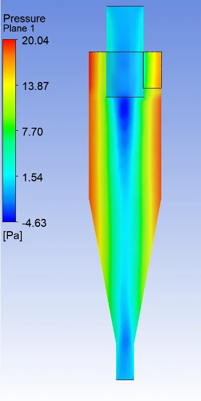
- Pressure Contour:
- Velocity Contour:
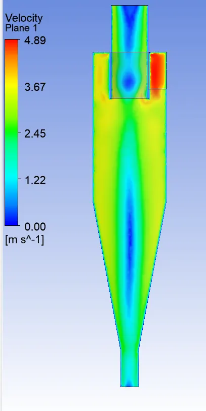
- Video Link:
https://drive.google.com/file/d/1mUGxACS3m1MQBdYWUIogvDyo-Zjn5B1U/view?usp=sharing
- Result:

Result_1:
|
Sr. No. |
Particle Dia. (m) |
Velocity (m/s) |
Tracked Particle |
Escaped Particle |
Trapped Particle |
Incomplete Particle |
Separation Efficiency (%) |
No. of Iteration |
Midplane Parameter |
||
|
Max. Pressure |
Min. Pressure |
Max Velocity |
|||||||||
|
1 |
1e-6 |
3 |
284 |
82 |
202 |
0 |
71.13 |
300 |
20.04 |
-4.63 |
4.89 |
|
2 |
3e-6 |
3 |
284 |
46 |
238 |
0 |
83.80 |
300 |
20.04 |
-4.63 |
4.89 |
|
3 |
5e-6 |
3 |
284 |
10 |
274 |
0 |
96.48 |
300 |
20.04 |
-4.63 |
4.89 |
- From the result it is clear that the separation efficiency increases with increase in particle size for constant inlet velocity.
- Pressure & Velocity are dependent on the Inlet Velocity, as it is not varied so this parameters also does not change.
Case-2: Varying inlet velocity for particle diameter of 5e-6m
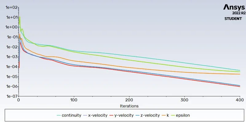
a) Particle diameter: 5e-6m, Velocity: 1m/s
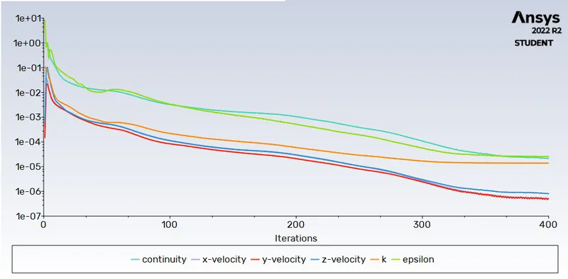
- Residual:
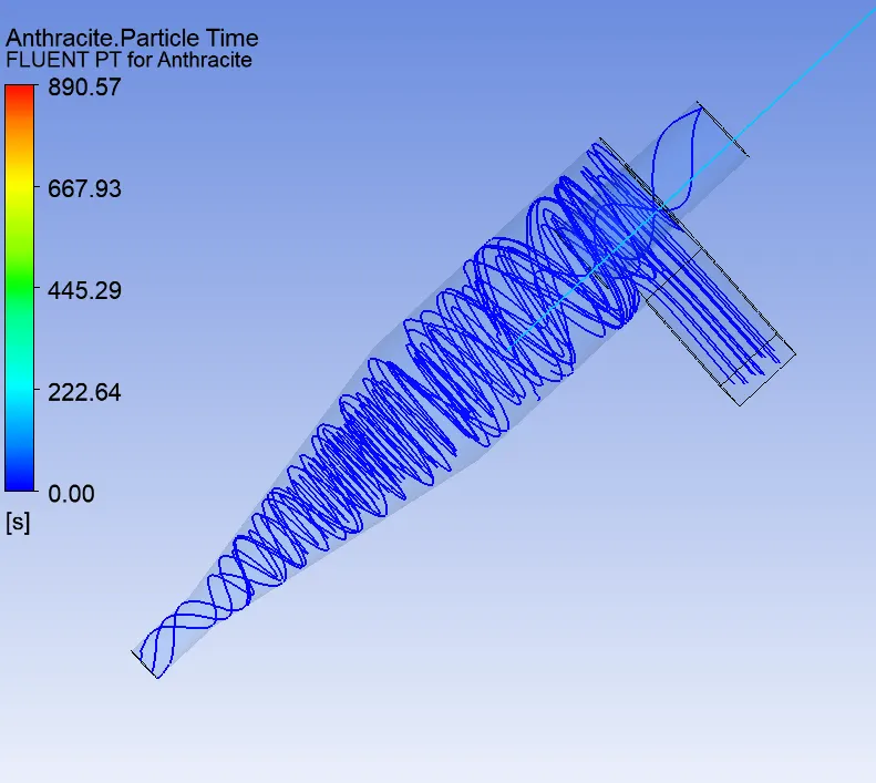
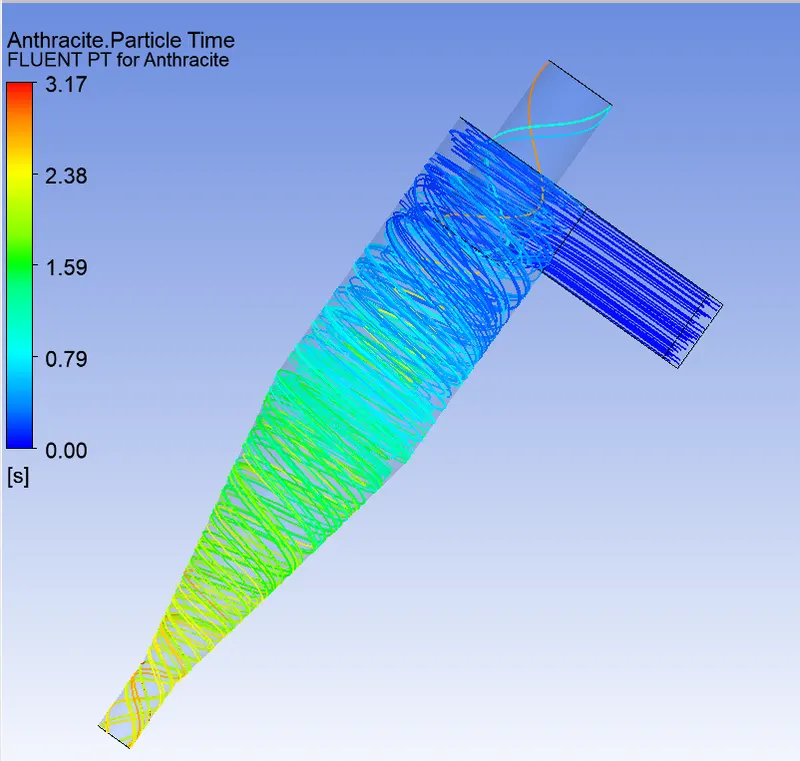
- Particle Flow Time:
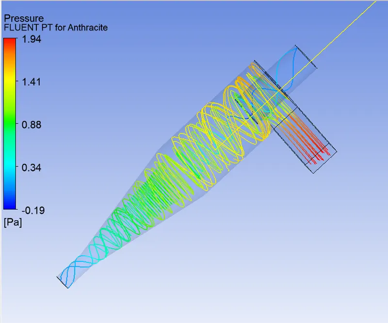
- Pressure Flow:
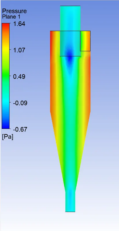
- Pressure Contour:
- Velocity Contour:
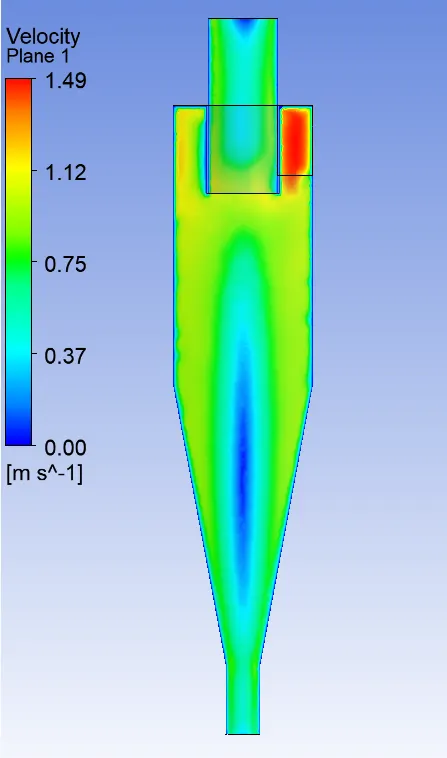
- Result

b) Particle diameter: 5e-6m, Velocity: 2.5m/s
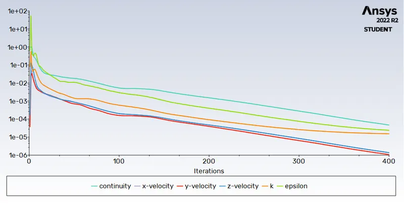
- Residual:
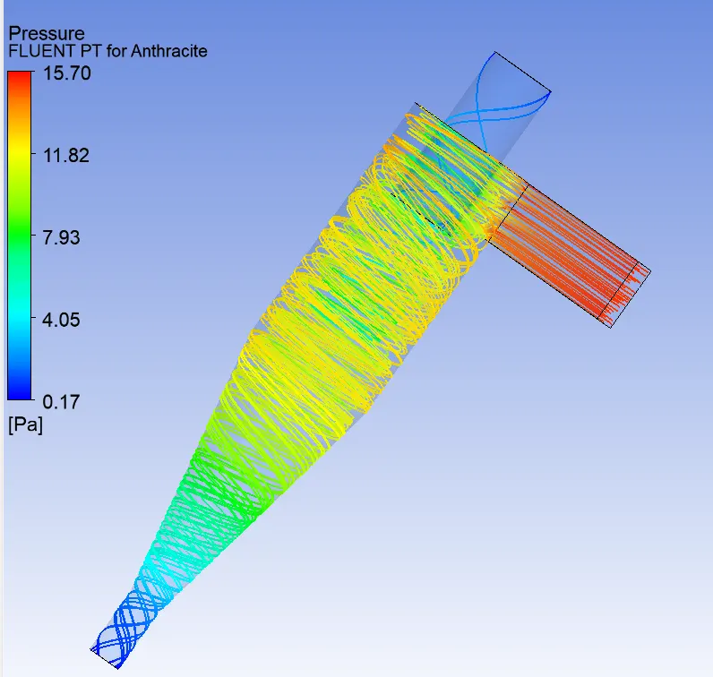
- Particle Flow Time:
- Pressure Flow:
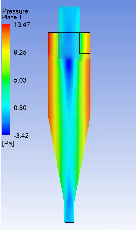
- Pressure Contour:
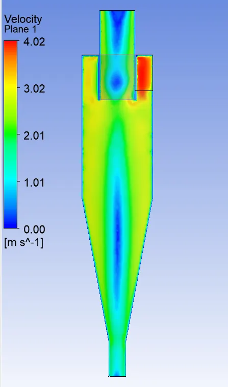
- Velocity Contour:
- Video Link:
https://drive.google.com/file/d/1n9hA7fVU_65qLObZdBTi24InwQvrUxoO/view?usp=sharing
- Result:

c) Particle diameter: 5e-6m, Velocity: 5m/s
- Residual:
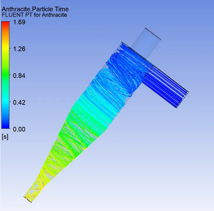
- Particle Flow Time:
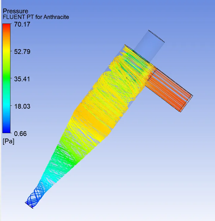
- Pressure Flow:
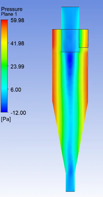
- Pressure Contour:
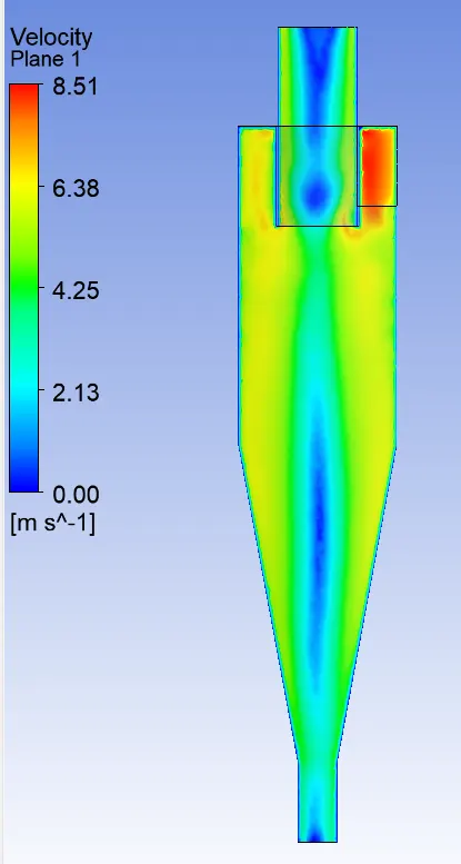
- Velocity Contour:
- Video Link:
https://drive.google.com/file/d/1vtfcnybonuB4xKxYcmTucQgKh2YaHi7B/view?usp=sharing
- Result:

Result_2:
|
Particle Dia. (m) |
Velocity (m/s) |
Tracked Particle |
Escaped Particle |
Trapped Particle |
Incomplete Particle |
Separation Efficiency (%) |
No. of Iteration |
Midplane Parameter |
||
|
Max. Pressure |
Min. Pressure |
Max Velocity |
||||||||
|
5e-6 |
1 |
284 |
54 |
84 |
146 |
29.58 |
400 |
1.64 |
-0.67 |
1.49 |
|
5e-6 |
2.5 |
284 |
16 |
268 |
0 |
94.37 |
400 |
13.47 |
-3.42 |
4.02 |
|
5e-6 |
5 |
284 |
0 |
284 |
0 |
100 |
400 |
59.98 |
-12 |
8.51 |
- From the result it is clear that the separation efficiency increases with increase in Inlet velocity for constant particle size.
- Pressure & velocity values vary with increase in inlet velocity.
- Vaccum pressure presence suggest that if there is presence of smaller particle, then those particles will not be removed by cyclone separator but will require additional fine filter to filter these particle.
Conclusion:
- Particles affecting the separator efficiency are particle density, size, volumetric flow rate, pressure drop, cone length, body length, ratio of accept port to body diameter and even the smoothness of the cyclone's internal surfaces.
- Particle with higher density can be removed more easily than smaller density particle. Efficiency of cyclone decreases with decrease in particle density.
- Larger particles can be more easily be removed than smaller particles, reduction in particles size reduces cyclone efficiency.
- Smaller diameter cone will extract much finer particles from gas stream than larger diameter cone.
- Smaller cyclone have higher efficiency rating, but is associated with high pressure drop & low volume flow rate.
- Large cyclone have lower efficiency rating, but is associated with low pressure drop & high volume flow rate. These types are more commonly used to remove larger particle.