Week 8 - Simulating Cyclone separator with Discrete Phase Modelling
Aim
To perform analysis on cyclone separator and calculate the separation efficiency and pressure drop.
Objective:-
- To write a few words about any four empirical models used to calculate the cyclone separator efficiency.
- To perform an analysis on a given cyclone separator model by varying the particle diameter from 1 μm to 5 μm and calculate the separation efficiency in each case. Discuss the results.
- To perform an analysis on a given cyclone separator model by varying the particle velocity from 1 m/sec to 5 m/sec and calculate the separation efficiency and pressure drop in each case. Discuss the results.
Introduction
Cyclone separator
Cyclones are devices that employ a centrifugal force generated by a spinning gas stream to separate particles from thecarrier gas. Their simple design, low capital cost and nearlymaintenance-free operation make them ideal for use as pre-cleaners for more expensive final control devices such as bag-houses or electrostatic precipitators. Cyclones are particularly well suited for high temperature and pressure conditions be-cause of their rugged design and flexible component materials.Cyclone collection efficiencies can reach 99% for particles big-ger than 5 μm, and can be operated at very high dust loading.Cyclones are used for the removal of large particles for both air pollution control and process use.
Application in extreme conditions includes the removal of coal dust in a power plant andthe use as a spray dryer or gasification reactor.
Discrete Phase Modelling
The discrete Phase Model is a subsection of Multiphase flows. A discrete phase model (DPM) is used when the aim is to investigate the behavior of the particles from a Lagrangian view and a discrete perspective. The difference between the Lagrangian and the Eulerian view is that fluid behavior in the Lagrangian view is examined based on particle tracking of a particulate flow, whereas fluid behavior is considered in the Eulerian view based on the assumption of a finite volume element in the fluid flow path.
In Discrete Phase Model, the continuous phase is solved using Navier-Stokes equations. At the same time, the discrete phase is simulated by tracking a large number of particles, bubbles, or droplets passing through the calculated continuous flow field. It should be noted that the discrete phase can exchange momentum, mass, and energy with the continuous phase. This method can be made much simpler by ignoring the interaction of particles (as well as droplets and bubbles) with each other. Of course, this can happen when the discrete phase, even with a large mass, has a much smaller volume (less than 10%) than the continuous phase. After each iteration of the continuous phase calculations, the particle paths are calculated and determined separately.
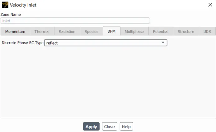
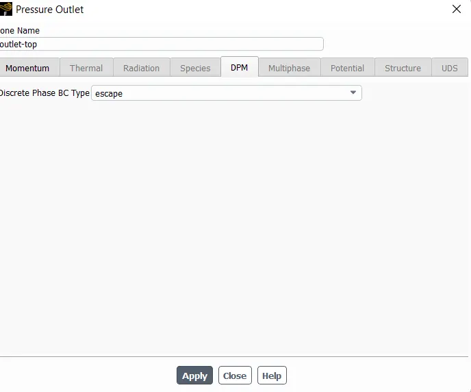
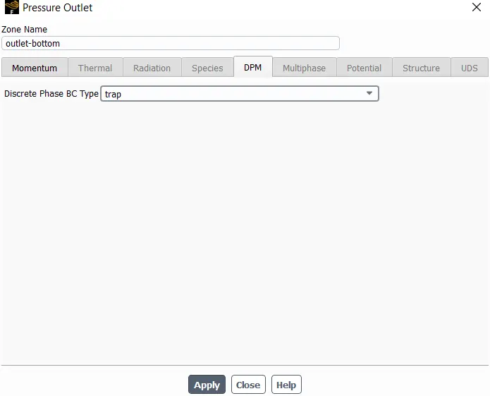
Boundary Conditions:-
Inlet and wall:- Reflect
Outlet(Top):- Escape
Outlet(Bottom/dustbin) - Trap
Separation effciency
Separation efficiency is the ratio of the concentration of particles removed from the incoming flow to the concentration of particles in the incoming flow.
`eta_(separation)=`Mass flow of outlet(top)/Mass flow of inlet*100
Four empirical models used to calculate the cyclone separator efficiency.
KOCH AND LICHT MODEL
Koch and Licht (1977) collection theory recognized the inherently turbulent nature of cyclones and the distribution of gas residence times within the cyclone. Koch and Licht describe particle motion in the entry and collection regions with the additional following assumptions:
• The tangential velocity of a particle is equal to the tangential velocity of the gas flow, i.e. there is no slip in the tangential direction between the particle and the gas.
• The tangential velocity is related to the radius of cyclone by: uRn = constant.
A force balance and an equation on the particles collection
yields the grade efficiency ηi.
LI AND WANG MODEL
The Li and Wang (1989) model includes particle bounce or re-entrainment and turbulent diffusion at the cyclone wall. A two-dimensional analytical expression of particle distribution in the cyclone is obtained. Li and Wang model was developed based on the following assumptions:
• The radial particle velocity and the radial concentration profile are not constant, for uncollected particles within the cyclones.
• Boundary conditions with the consideration of turbulent diffusion coefficient and particle bounce re-entrainment on the cyclone wall.
IOZIA AND LEITH MODEL
Iozia and Leith (1990) logistic model is a modified version of Barth (1956) model which is developed based on force balance. The model assumes that a particle carried by the vortex endures the influence of two forces: a centrifugal force, Z, and a flow resistance, W.
LAPPLE MODEL
Lapple (1951) model was developed based on force balance without considering the flow resistance. Lapple assumed that a particle entering the cyclone is evenly distributed across the inlet opening. The particle that travels from inlet half width to the wall in the cyclone is collected with 50% efficiency.
Solving & Modelling approach
Pre-processing
Spaceclaim
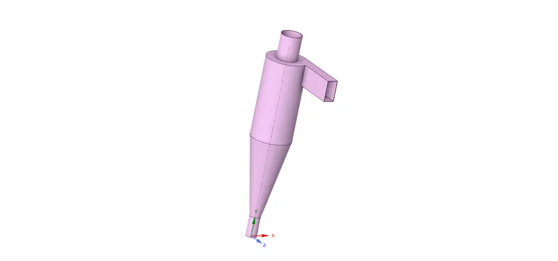
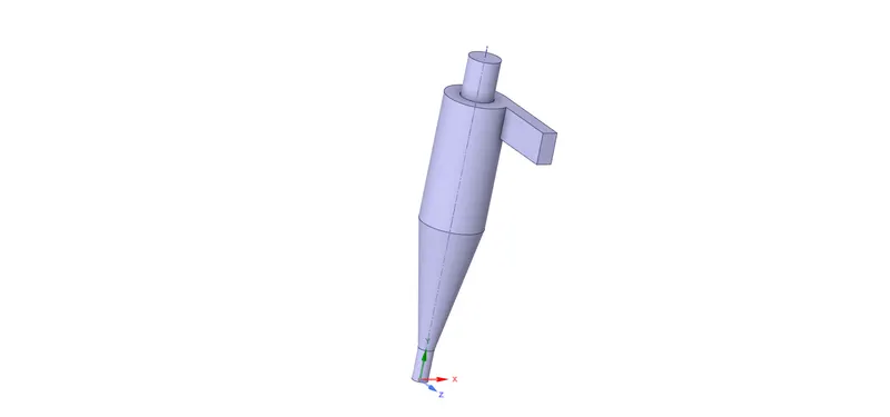
The step file is imported into spaceclaim and the fluid volume is extracted using the prepare`rarr`volume extract`rarr`edge selection
Then the solid region is suppressed for physics.
Solid region
Fluid volume
Meshing
The fluid body is choosen and for the mesh shape insert`rarr`method`rarr`cartesian is chosen
Mesh size is set to 5mm and the inlet and the top outlet and bottom outlet are defined.
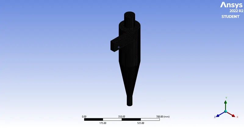
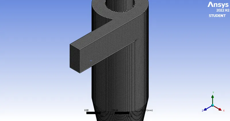
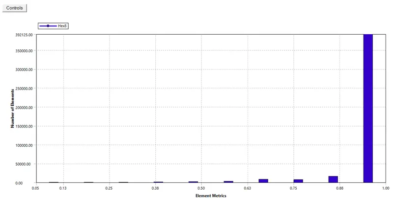
No of elements : 427871
Solver
Set-up
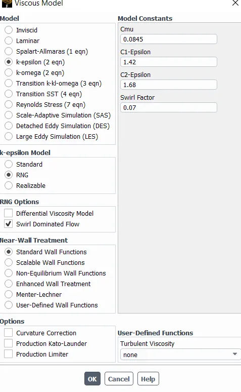
The process begins with setting the gravity. Then the k-`epsi``rarr`RNG`rarr`swirl dominated flow is selected.
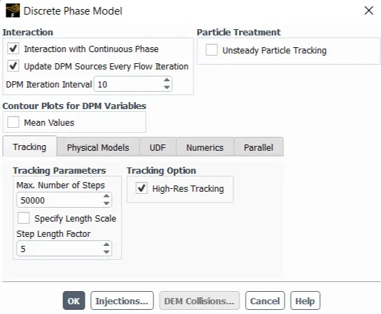
Following this Discrete modelling phase is selected and the interaction with continuous phase is selected.
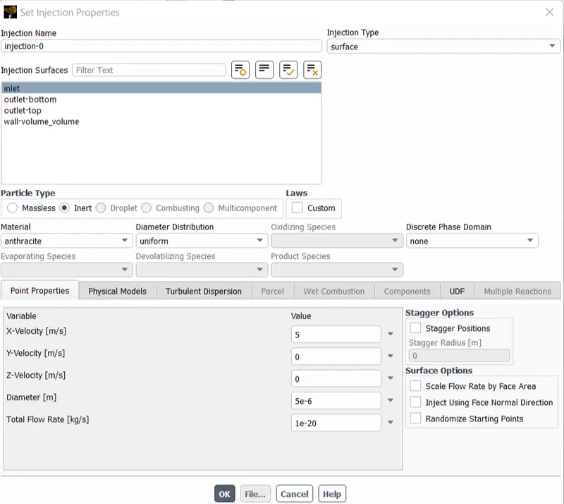
The injection is created for the inlet surface and boundary conditions are set
Inlet and wall:- Reflect
Outlet(Top):- Escape
Outlet(Bottom/dustbin) - Trap
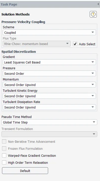
Second order upwind is chosen as the solution method.
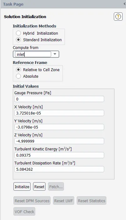
Then the standard initialisation is done from the inlet and iterated.
Post-Processing
CFD-Post
Case-1
Partical diameter : 1e-6`mum`Velocity : 3m/s(inlet velocity is same as particle velocity)
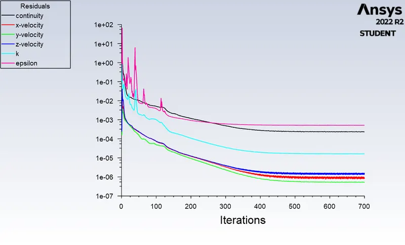
DPM Iteration ....
number tracked = 378, escaped = 78, trapped = 300 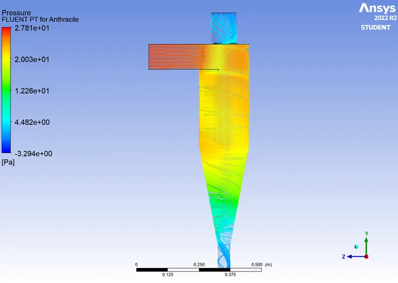
Animation
Case-2
Partical diameter : 5e-6`mum`Velocity : 3m/s
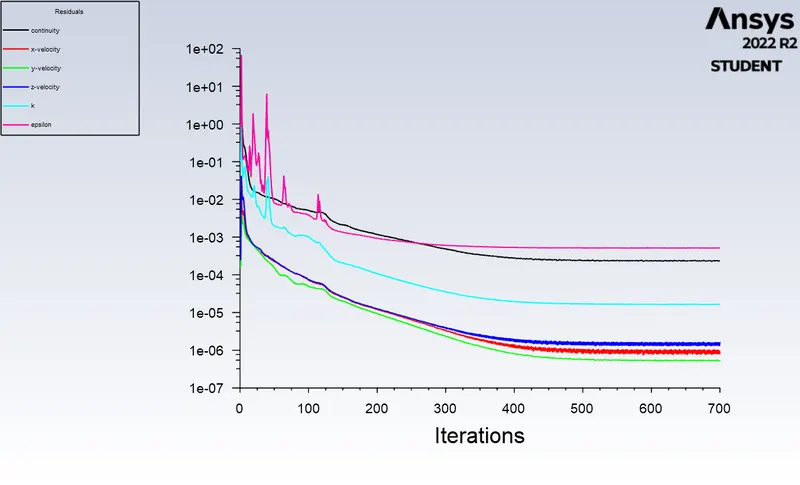
DPM Iteration ....
number tracked = 378, escaped = 133, trapped = 245
Animation
| particle diameter with constant velocity(3m/s) | Separation Efficiency |
| 1e-6`mum` | `0.0152209/0.0183745=82.84`82.84 |
| 5e-6`mum` | `0.0152209/0.0183745=82.84` |
Case-3
Partical diameter : 5e-6`mum`Velocity : 1m/s
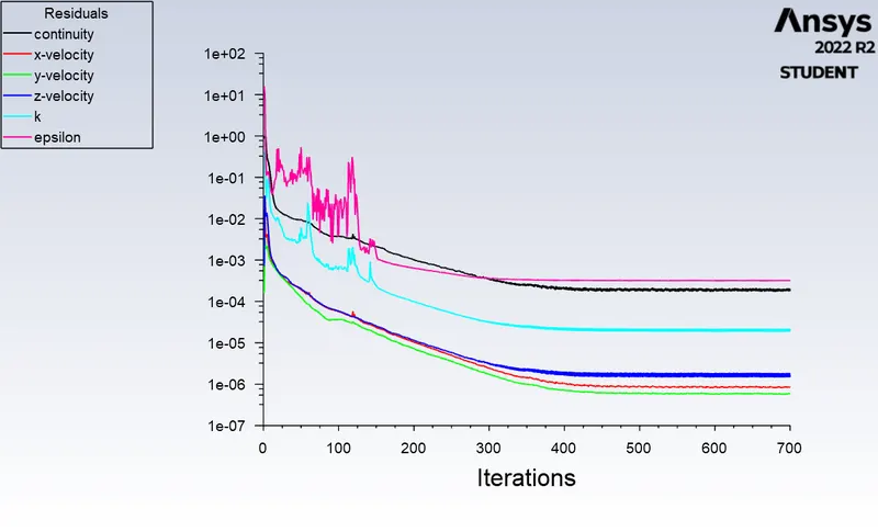
DPM Iteration ....
number tracked = 378, escaped = 67, trapped = 311
Maximum pressure : 2.539pa
Mininum pressure : -0.6436pa
Pressure drop : 3.173pa
Animation
Case-4
Partical diameter : 5e-6`mum`Velocity : 5m/s
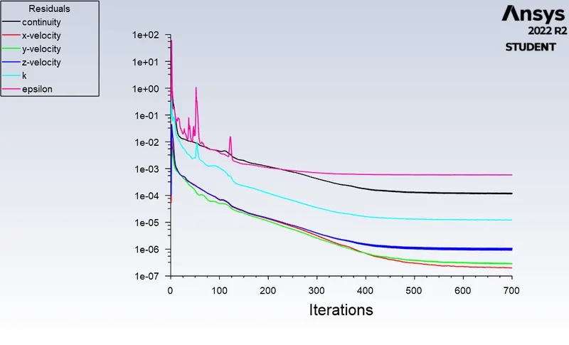
DPM Iteration ....
number tracked = 378, escaped = 80, trapped = 276, incomplete = 22
Animation
Maximum pressure : 79.80pa
Mininum pressure : -7.490pa
Pressure drop : 87.29pa
| Varying inlet velocity with constant particle diameter(5e-6`mum`) | Pressure drop | Separation efficiency |
| 1m/s | 3.173 | `0.00506578/0.00612483=82.70` |
| 5m/s | 87.29 | `0.025343/0.0306242=82.75` |
Observation
For cases 1 and 2 as particle diameter increases (constant inlet velocity) the number of particles getting trapped decreased.
For cases 3 and 4 as inlet velocity increases (constant partical diameter) the separation efficiency increased.
Conclusion
Thus the analysis on cyclone separator and calculation of the separation efficiency and pressure drop has been done.
References
https://www.sciencedirect.com/science/article/pii/S0307904X06000291