Week 8 - Simulating Cyclone separator with Discrete Phase Modelling
AIM of the project- To perform analysis on cyclone separator and calculate the separation efficiency and pressure drop.
Theory of the cyclone separator- Cyclonic separation is a technique of removing particulates from the air, gas, and liquid stream without the use of filters through vortex separation. When removing particulate matter from liquid, a hydrocyclone is used; while from gas, a gas cyclone is used. Rotational effects and gravity are used to separate mixtures of solids and fluids. The method can also be used to separate fine droplets of liquid from a gaseous stream.
A high-speed rotating (air)flow is established within a cylindrical or conical container called a cyclone. Air flows in a helical pattern, beginning at the top (wide end) of the cyclone and ending at the bottom (narrow) end before exiting the cyclone in a straight stream through the center of the cyclone and out the top. Larger (denser) particles in the rotating stream have too much inertia to follow the tight curve of the stream, and thus strike the outside wall, then fall to the bottom of the cyclone where they can be removed. In a conical system, as the rotating flow moves towards the narrow end of the cyclone, the rotational radius of the stream is reduced, thus separating smaller and smaller particles. The cyclone geometry, together with volumetric flow rate, defines the cut point of the cyclone. This is the size of particle that will be removed from the stream with a 50% efficiency. Particles larger than the cut point will be removed with a greater efficiency and smaller particles with a lower efficiency as they separate with more difficulty or can be subject to re-entrainment when the air vortex reverses direction to move in direction of the outlet. How well the cyclone separator can remove the particles actually depends on the diameter of the particle . If there are a large amount of the lighter particulate matter less number of particles are to be removed. Because of this cyclone separators works best on flue gas that contains large amounts of big particulates.
#) Empirical models that are used to find out the cyclone separation efficiency -
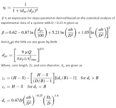
1) Iozia and Leith model- Iozia and Leith logistic model is a modified version of the Barch model which is developed based on the force balance. This model assures that a particle carried by the vortex endures the influence of 2 forces centrifugal force z,a flow resistance,w length,zc, and core diameter.
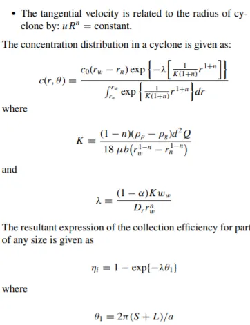
2) The Li and wang model- The Li and wang moel includes particle bounce and e entrainment and turbulent diffusion at the cyclone wall. A 2D analytical expression of particle distribution in the cyclone is obtained.
The radial particle velocity and the radial particle velocity and the radial concentration profile are not combat for uncollected particle within the cyclones.
Boundary condition with the consideration of turbulent diffusion coefficient and particle bounce re-entrainment on the cyclone wall are
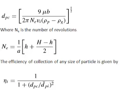
3) Lapple model- It is based on the force balance without considering the flow resistance lapple assured that particle entering the cycle is evenly distributed across inlet. The semi empirical relation obtained is as follows-
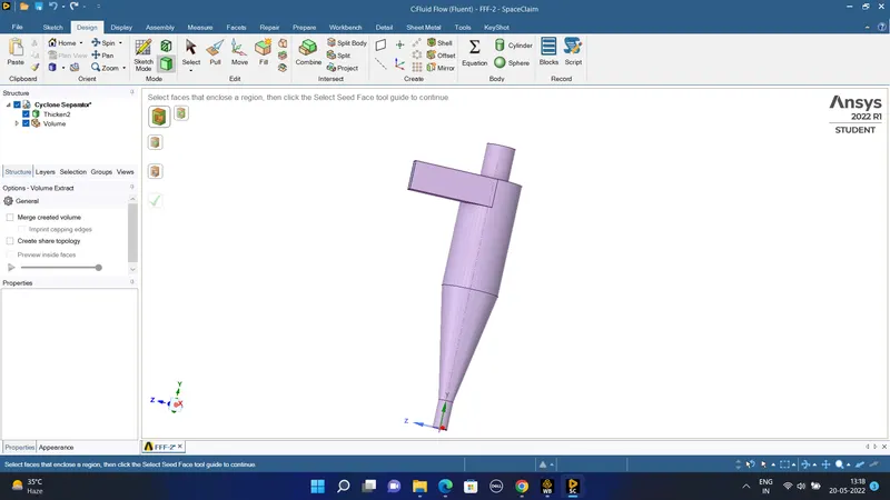
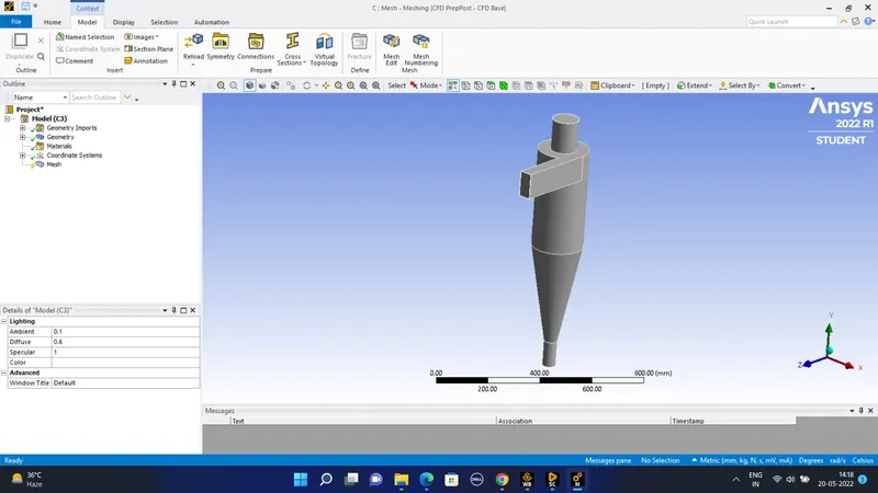
The geometry of the cyclone separator in the spaceclaim-
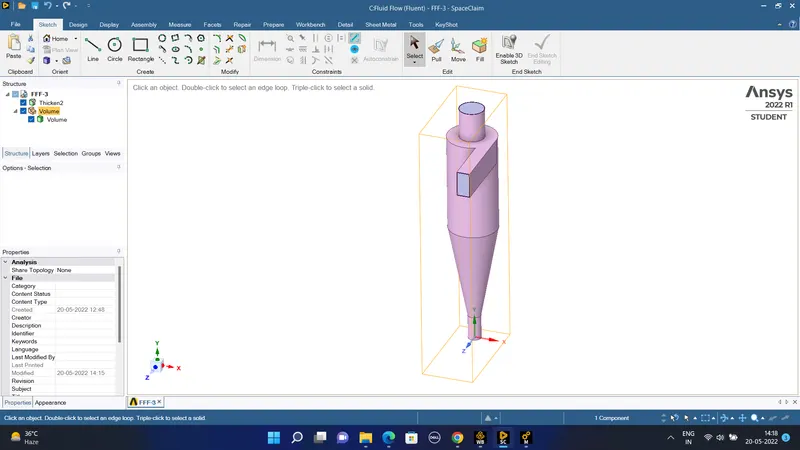
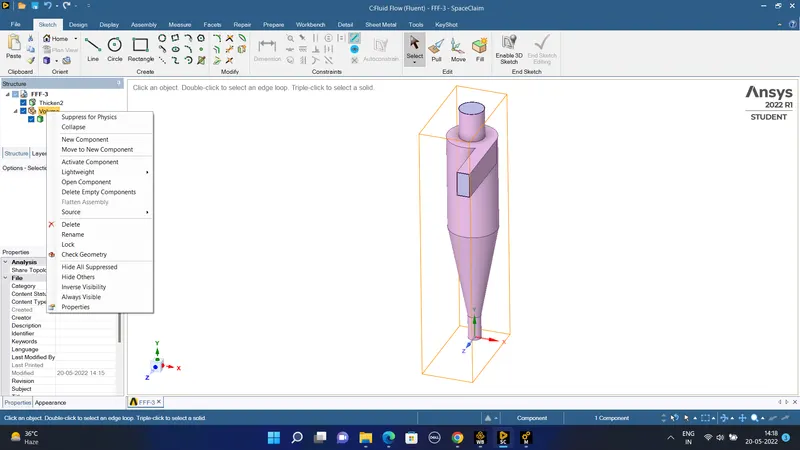
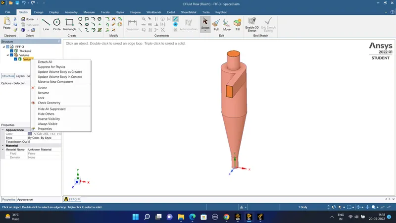
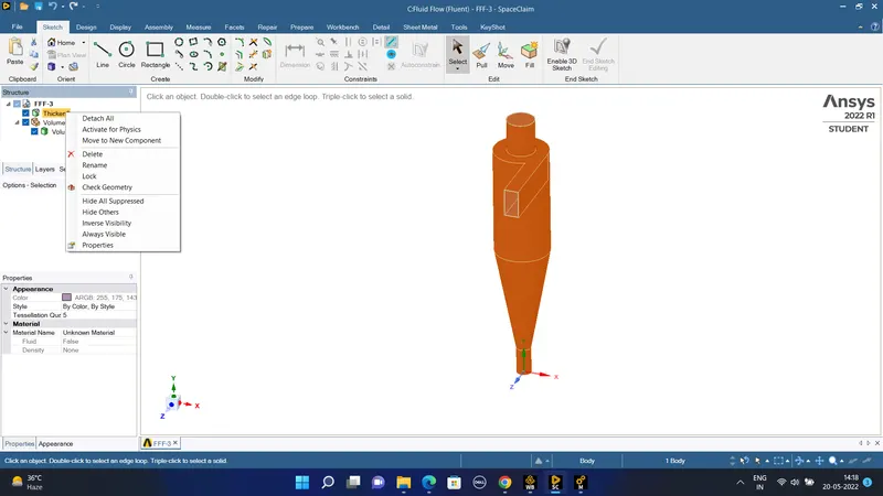
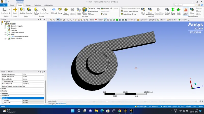
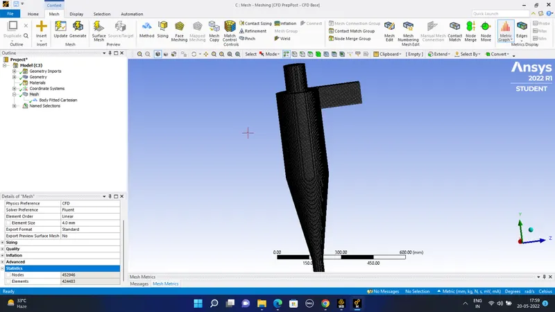
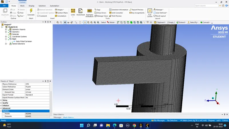
#) The geometry of the object in the mesh-
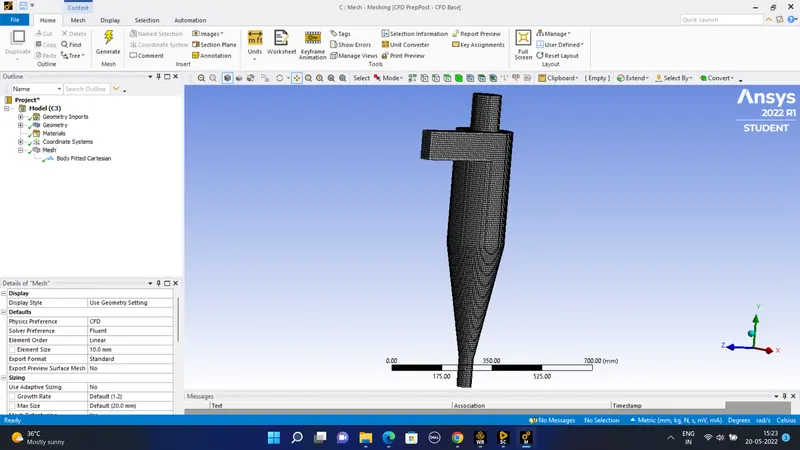
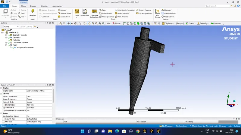
The element size of 10 mm is given so the mesh generated in the body fitted cartesian form is as-
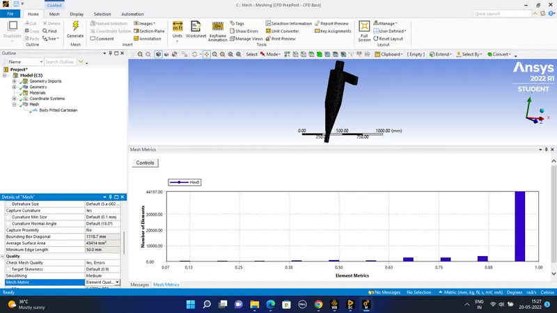
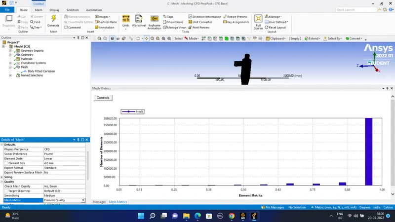
The mesh metrices are as follows-
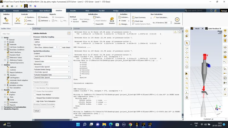
Now in the setup or the fluent solver is of -
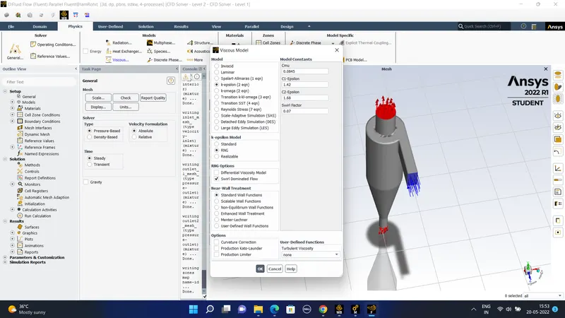
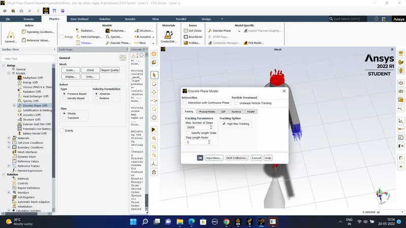
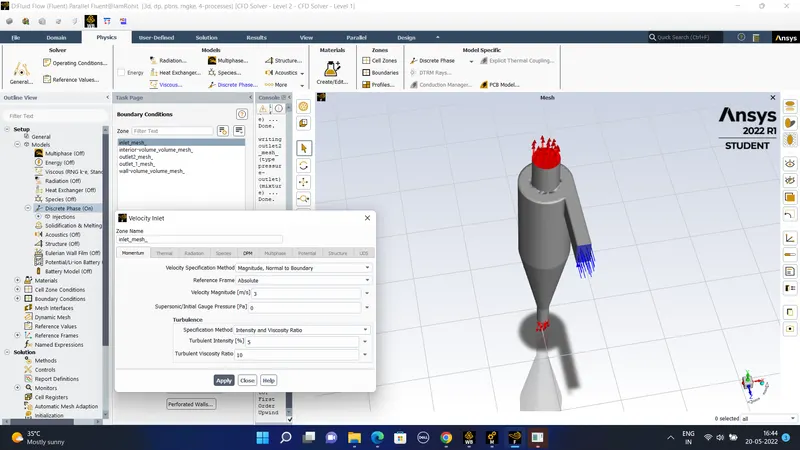
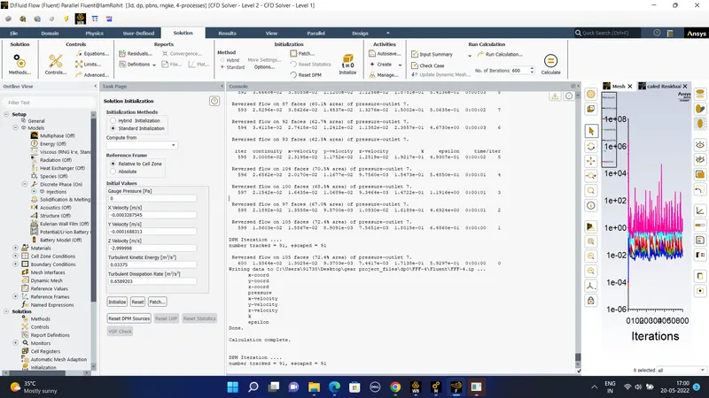
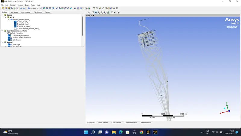
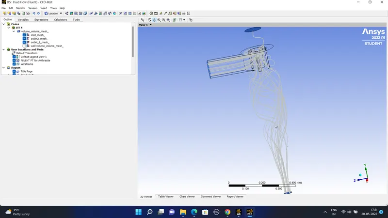
#) For the diameter of 5 nanometer of the air particles we have to refine the mesh so that the more particles are to be captured within the domain.
#) Now the number of particles tracked is increased to the number of 378.
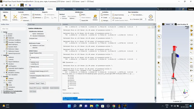
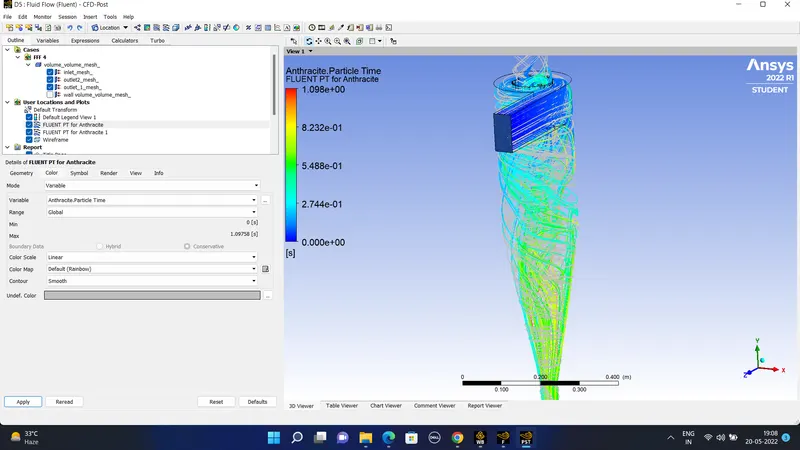
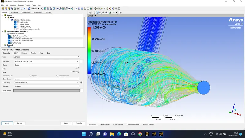
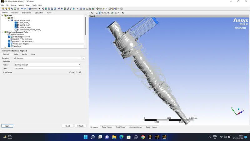
The animation of the particles are- https://drive.google.com/file/d/1xqA0LTaaW4I4VIbaitfIdTj2bGr1UE39/view?usp=sharing
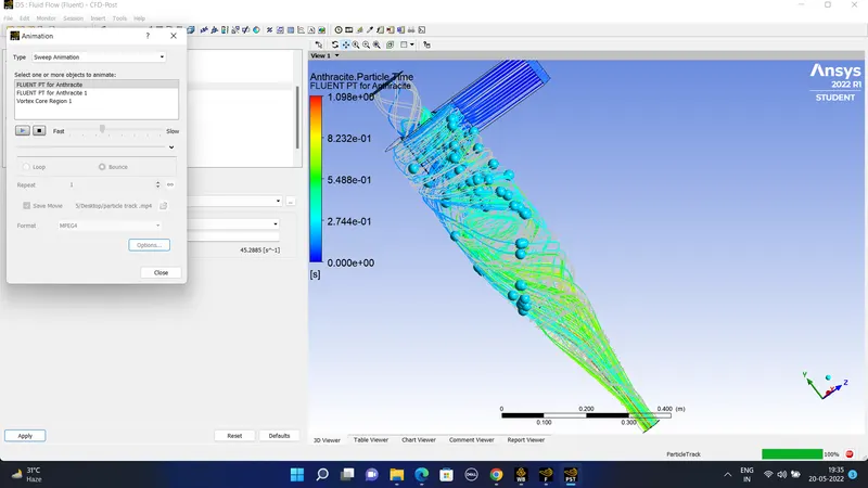
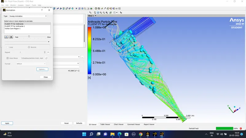
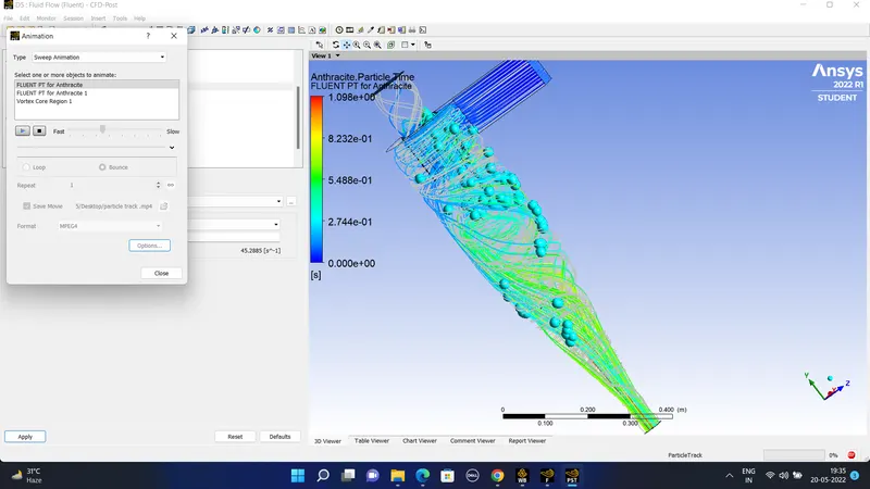
#) For the particle dimeter of 1 micro meter we can have the following -
The results obtained are as of- https://drive.google.com/file/d/1WXGTkzuXgc8pyXhxhSpSNTCGh9QABCL2/view?usp=sharing
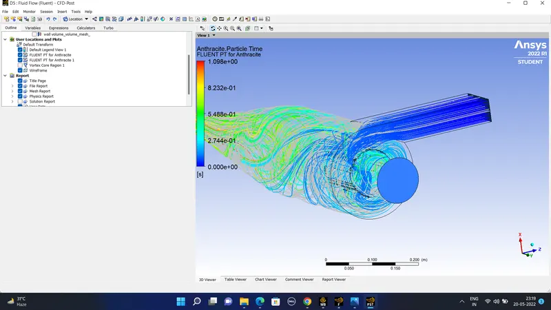
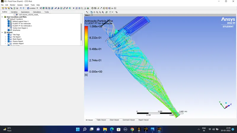
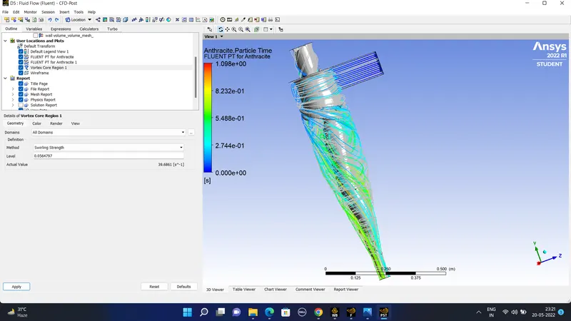
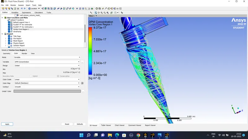
case 2) Here the velocity is varied this will lead to the varying contours of the particle .
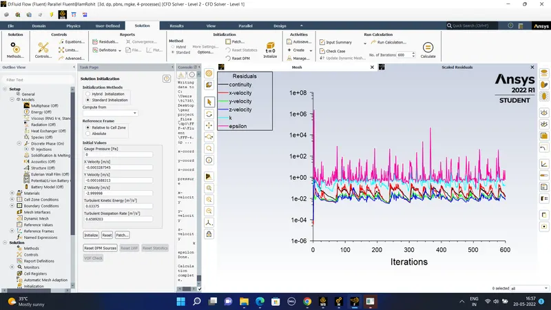
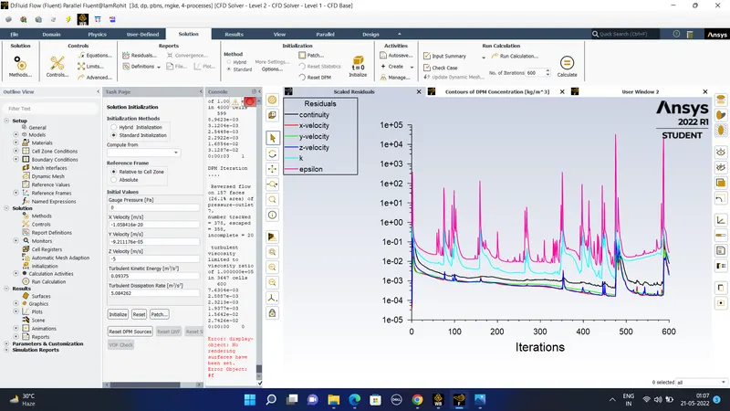
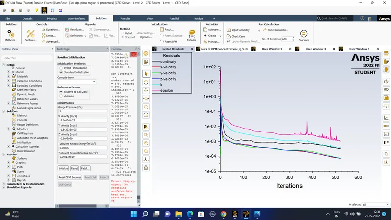
For velocity v = 5 m/sec and the particle diameter of d = 5 micrometer is used . The residual obtained after 600 iterations using the SIMPLE method of scheme is of the following.
The residuals obtained after the 600 iterations-
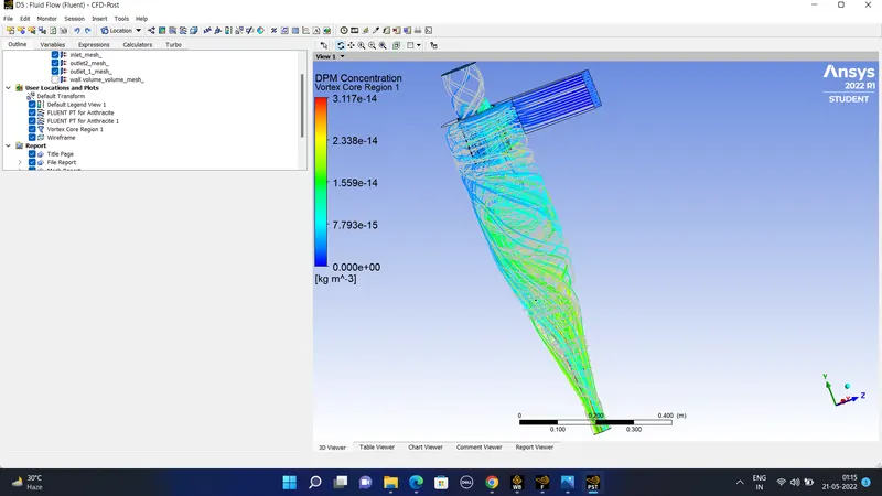
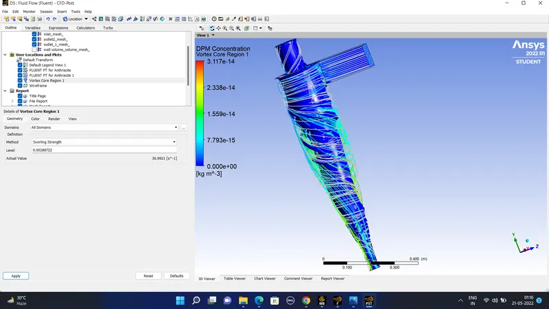
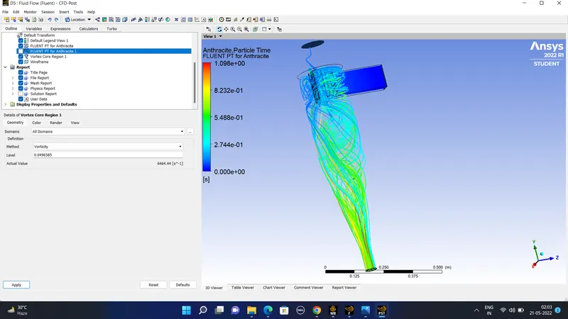
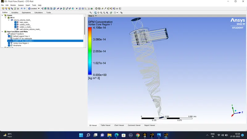
The animation file is- https://drive.google.com/file/d/1VMCgVvxdvQX-UViEikAQYk-8AVvj5nre/view?usp=sharing
https://drive.google.com/file/d/1WoARcispq76Yoqq5fb7VFJBSe3JftxhD/view?usp=sharing
3) For velocity = 1 m/sec and the same diameter d = 5 micro meter.
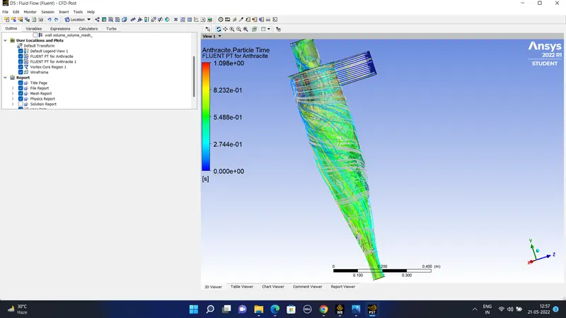
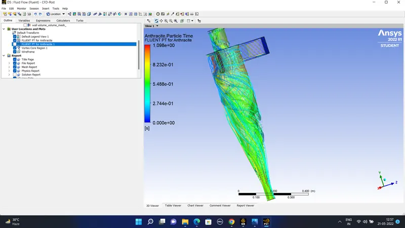
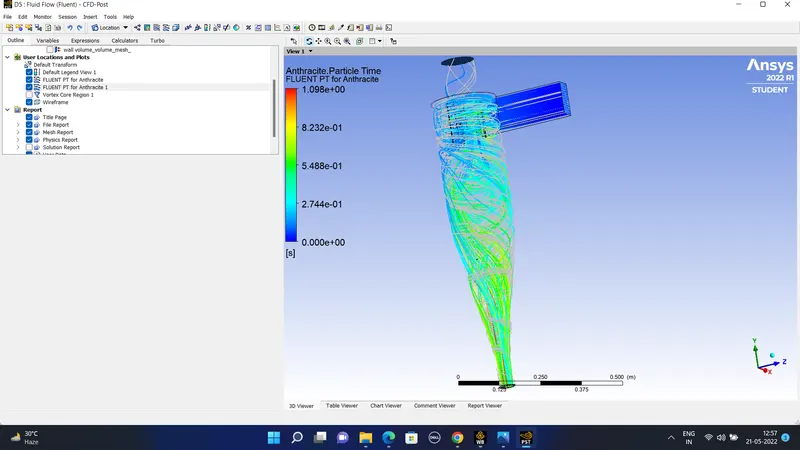
The residuals and the contours of the particle tracking obtained area as follows-
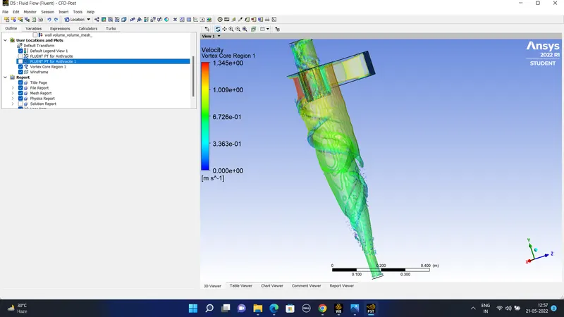
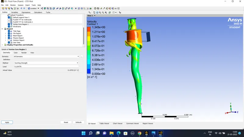
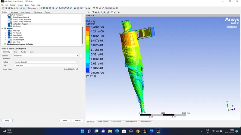
The contour of the vortex is of -
#)The animation file is -
https://drive.google.com/file/d/125xzeta1KCF3vU_0OIGpK-1j0MiG-Z_Z/view?usp=sharing
#) To calculate the separation efficiency we have to use the following formula-
separation efficiency = a number of particles trapped/ number of particles tracked.
case particle diameter flow velocity number of particles tracked number of particles trapped separation efficiency
1a 1 3 368 170 47
1b 3 3 368 190 51.6
1c 5 3 368 230 62.5
#) Conclusions-
1) When the diameter of the particle varies from 1 micrometer to 5 micrometer by keeping flow velocity constant then th separation efficiency increases.
2) In the same manner if the velocity is increased by keeping the diameter constant then also the separation efficiency increases because the number of particles trapped in that case also increases.