Week 8 - Simulating Cyclone separator with Discrete Phase Modelling
1.Aim:
- To perform analysis on cyclone separator and calculate the separation efficiency and pressure drop.
2.Introduction:
- A cyclonic separation is a method of removing particulates from an air, gas or liquid stream, without the use of filters, through vortex separation. When removing particulate matter from liquid, a hydrocyclone is used; while from gas, a gas cyclone is used.
- A high speed rotating air flow is established within a cylindrical or conical container called a cyclone. Air flows in a helical pattern, beginning at the top wide end of the cyclone and ending at the bottom narrow end before exiting the cyclone in a straight stream through the center of the cyclone and out the top.
- Larger denser particles in the rotating stream have too much inertia to follow the tight curve of the stream, and thus strike the outside wall, then fall to the bottom of the cyclone where they can be removed. In a conical system, as the rotating flow moves towards the narrow end of the cyclone, the rotational radius of the stream is reduced, thus separating smaller and smaller particles.
- The cyclone geometry, together with Volumetric flow rate, defines the cut point of the cyclone. This is the size of particle that will be removed from the stream with a 50% efficiency. Particles larger than the cut point will be removed with a greater efficiency, and smaller particles with a lower efficiency as they separate with more difficulty or can be subject to re-entrainment when the air vortex reverses direction to move in direction of the outlet.
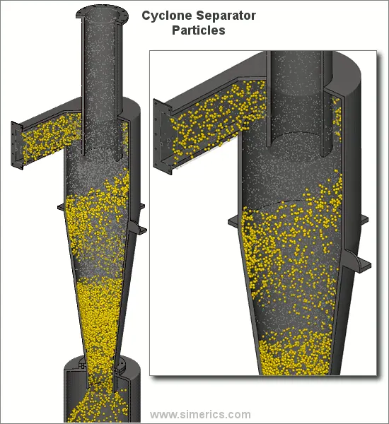
2.1 Removed components from cyclone separation:
- Dust
- Partcles: Abrasive,Corrosive,Adhesive, Explosive
2.2 Factor affecting the efficiency
- There are several factors that can affect a cyclone separators efficiency. These include particle density, particle size, volumetric flow rate, pressure drop, cone length, body length, ratio of accept port to body diameter, and even the smoothness of the cyclone’s internal surfaces. We will now discuss the more important design aspects in greater detail.
- Particle density is one of the most deciding factors affecting a cyclone’s ability to remove entrained particles. Dense particulates such as ferrous oxides can be separated with a 99% or greater efficiency, irrespective of particle size. When the particle density decreases, the efficiency decreases.
- Particle size is a large design consideration effecting a separator’s efficiency. Larger particles can be more easily separated than smaller particles. Particles smaller than five microns are difficult to separate without using very small separators. Particle exceeding 200 microns can often be separated using other means such as gravity-settling chambers. A reduction in particle size will give a corresponding reduction in efficiency.
2.3 Advantages and Disadvantages
There are many advantages associated with cyclone separators, some of these include:
- Cheap to purchase.
- Low maintenance.
- Suitable for high temperatures.
- Suitable for liquid mists.
- Do not require much space.
Some disadvantages are associated with cyclone separators, but these disadvantages can be reduced in severity if the correct separator is selected for the correct application. Disadvantages may include:
- Increased operating costs associated with the pressure drop (assuming large pressure drop).
- Inefficient when handling small/fine particles.
- Not suitable for ‘sticky’ substances.
2.4 Applications
Cyclone Separator is widely used for removal of Dust particle and recovery of catalytic dust
- Petrochemical Industry
- Cement Industry
- Paper and Pulp Industry
- Textile Industry
- Grain Processing
- Food and Beverage Processing
3. Empirical models for cyclone separator efficiency:
3.1 Iozia and Leith model
-
This model is used with the efficiency model of Iozia and Leith to develop an optimization curve which predicts the minimum pressure drop and the dimension ratios of the optimized cyclone for a given aerodynamic cut diameter, d. The effect of variation in cyclone height, cyclone diameter, more » and flow on the optimization is determined.
3.2 Li and wang model
- Li and Wang disregarded the turbulent diffusion inside the CS and the particle settling velocity in the z direction. The equations of continuity and the conservation of particles led to a new model for particle distribution inside the CS.
3.3 Koch and Licht model
- Koch and Licht Model residence times within the cyclone. K och and Licht described tangential direction between the particle and the gas = constant
3.4 Lapple model
- Lapple Model was developed based on force balance without considering the flow resistance. Lapple assumed that a particle entering the cyclone is evenly distributed across the inlet opening. The particle that travels from inlet half width to the wall in the cyclone is collected with 50% efficiency.
3.5 Steps involves in Ansys Fluent software
- Geometry: Construct a two or three dimensional representation of the object to be modelled and tested using the work plane co-ordinate system within Ansys.
- Mesh: At this point understands the makeup of the part. Now define how the modelled system should be broken down into finite pieces.
- Setup: This case setup will be done using Ansys Fluent.
- Solution: Ansys Fluent where run time result visualization is done.
- Results: Post processing of results will be done using CFD post.
4.Procedure:
4.1Geometry
1.Open new project, by clicking on Fluid flow(Fluent) in Ansys workbench.
2.Now click on geometry to Cyclone separator model. It will redirect to Spaceclaim, Ansys geometry model.
3.We are to analyse the cyclone separator, To supress that we need to extract volume of Separator. Go to prepare menu and click on volume extract. Switch to edge selection and select three outer edges and click on green check button.
4.Hide solid by unchecking it from structure menu to see volume, which we have extracted. Supress solid by clicking on option supress for physics.
5.Exit from Spaceclaim and click on mesh to open mesh menu.
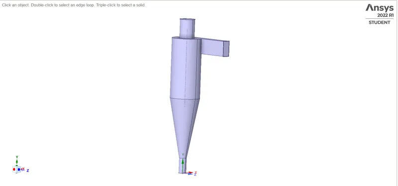
Fig: Geometry
4.2 Meshing
6.Select outer face and press right click of mouse, it will open a menu. Click on option create named selection and write suitable name for face. Repeat for other faces
7. Now click on mesh option and choose generate mesh. It will generate mesh according to some predefined criteria. Element size can be selected but it is going to affect simulation time. Selection plane can be created to see inner portion of geometry.
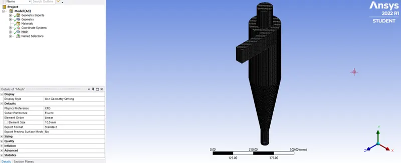
Fig: Mesh
4.3 Setup and solution
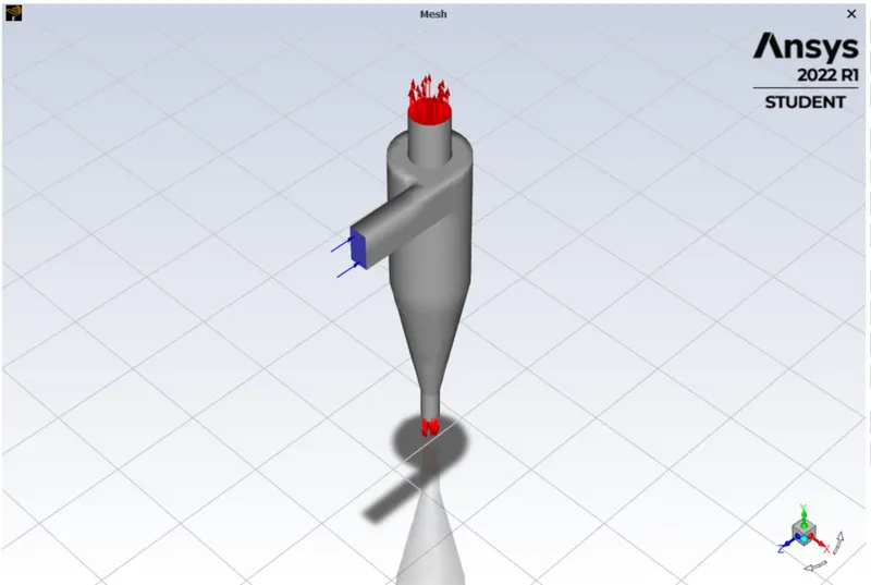
Fid: Setup
8.Exit mesh and open setup. First, Check mesh, it is throwing no error then only we can proceed further. We are going to do pressure based steady state simulation, So choose these options on task page.
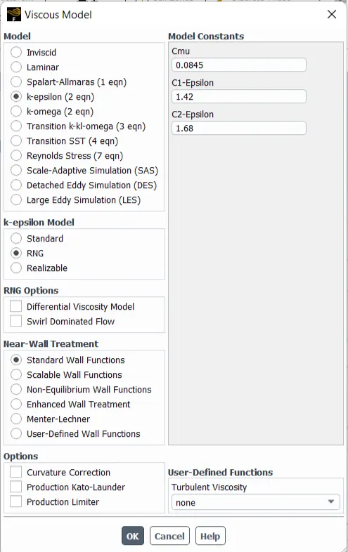
9. Go to physics menu and select viscous model. It will open a menu, choose realizable K-epcilan model and close it.
10.Now go to boundaries option to set boundary conditions. Select inlet x and click on option edit. It will open a menu, Where it is thermal radiation, momentum etc. Put the value of velocity as 3m/s and go to DPM parameter to set a types.
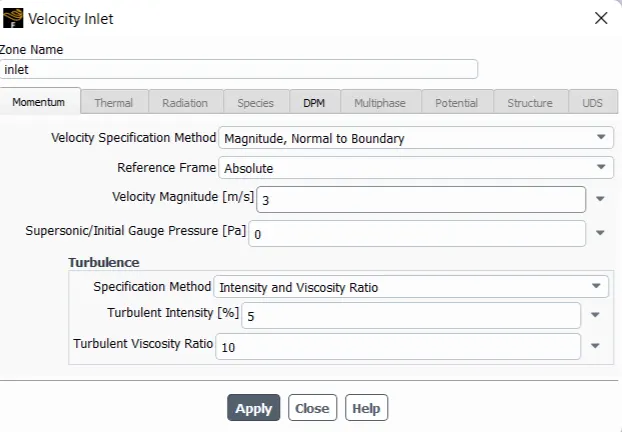
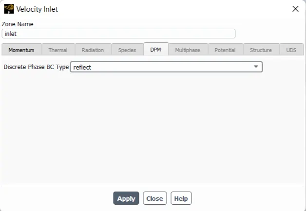
Fig:Inlet Boundary conditions
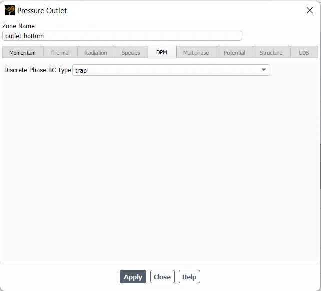
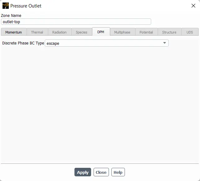
Fig: Outlet boundary condition
11. Move to discrete phase and Give the injection value.
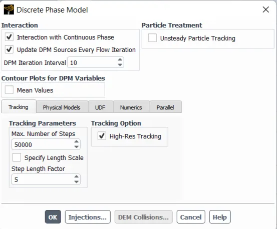
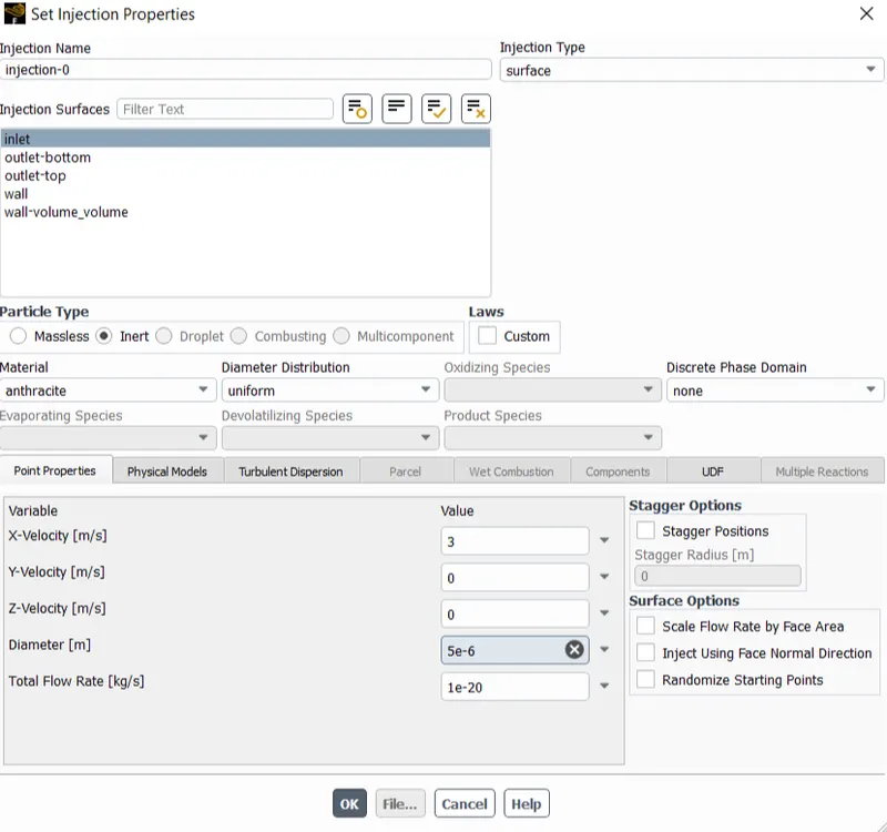
FIg: Discrete Phase
12.Now click on Standard intialization compute from inlet to calculate approximate values of velocity and pressure.
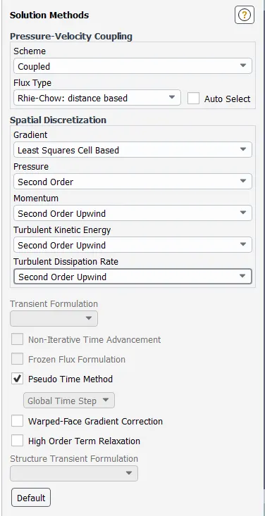
Fig: Standard Instilizition
13.Change the number of iteration 200 and click on calculate.
14.Exit setup and double click on result to open CFD post.
5.Results
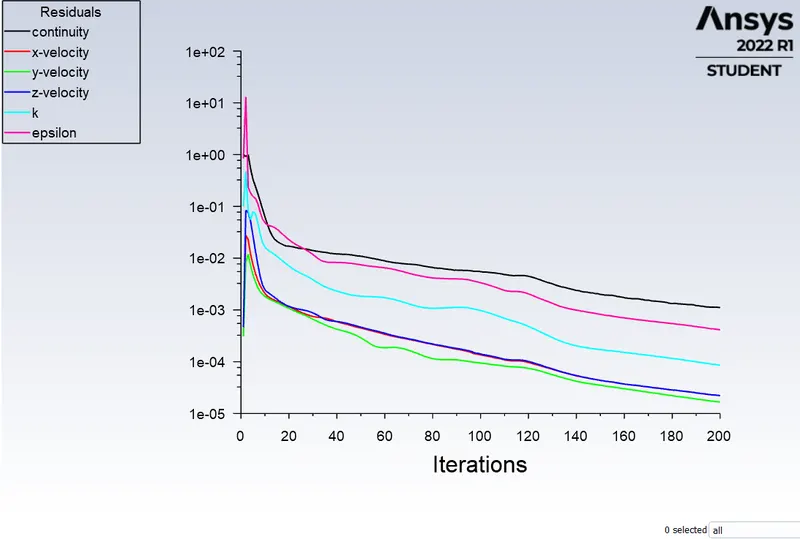
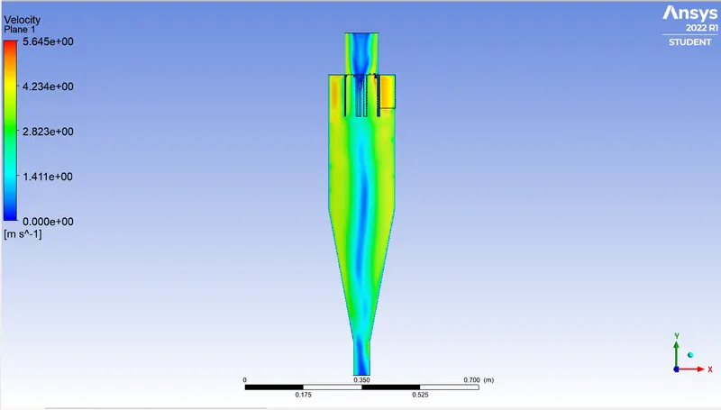
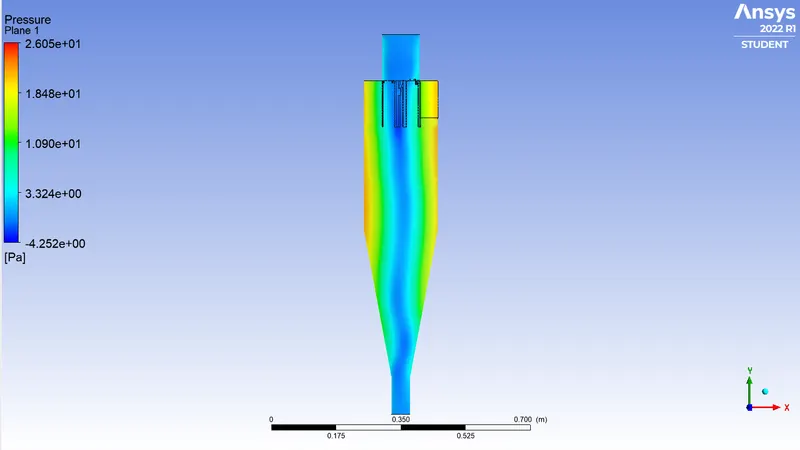
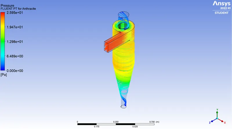
Case: 1.1
- Velocity = 3m/s
- Size of particle = 1e-6 m
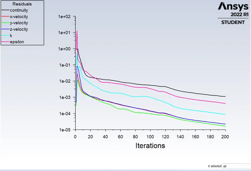
Residual
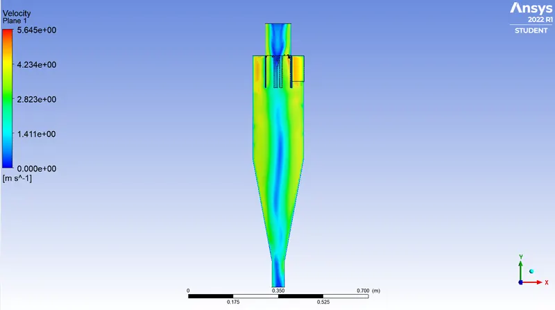
Plane velocity
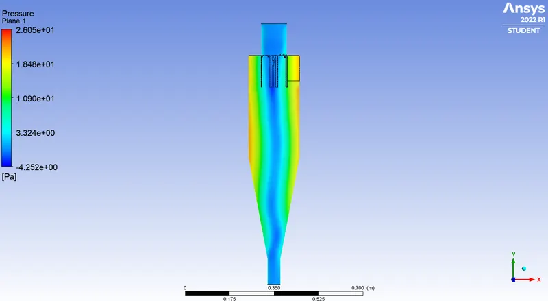
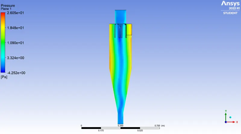
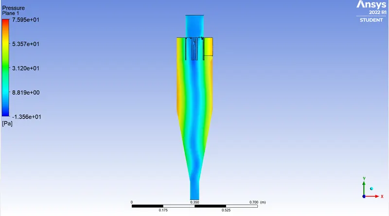
Pressure plane
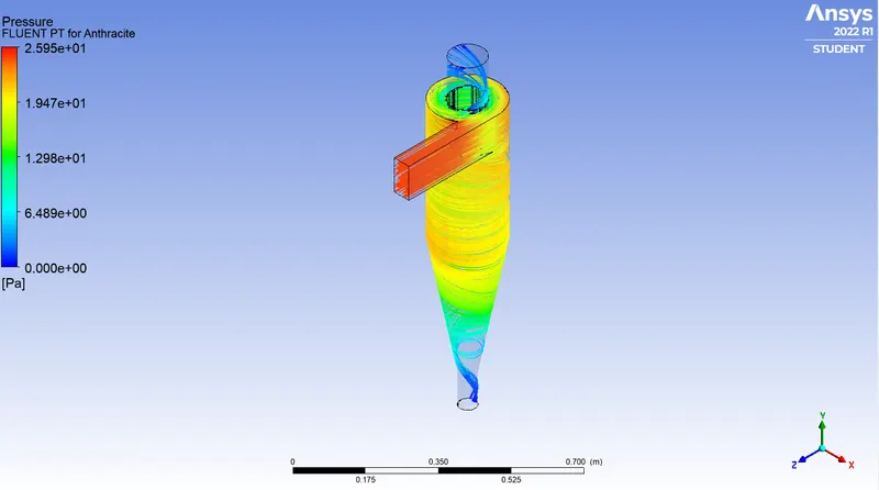
Pressure at Fluent PT for Anthracite
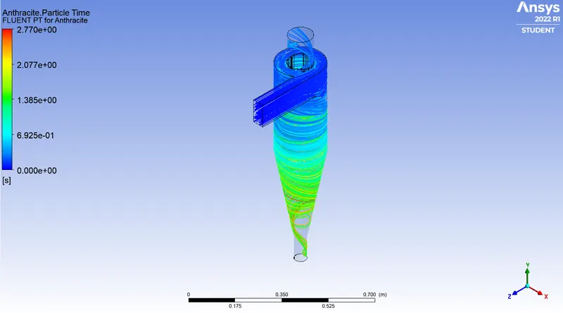
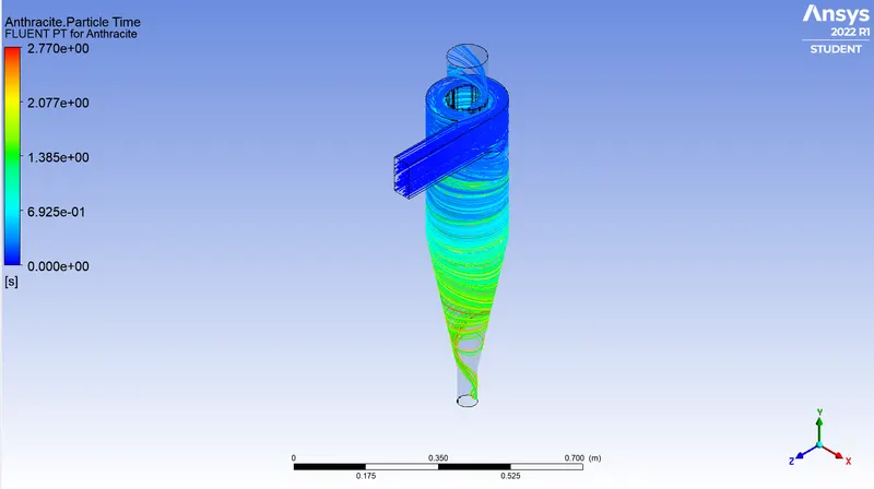
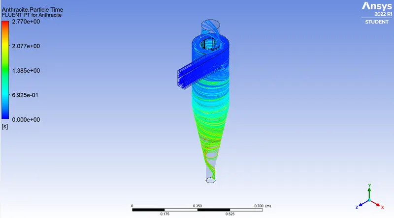
Particle time at Fluent PT for Anthracite
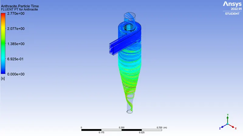
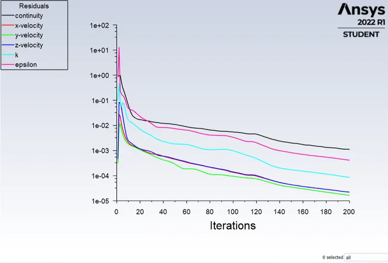
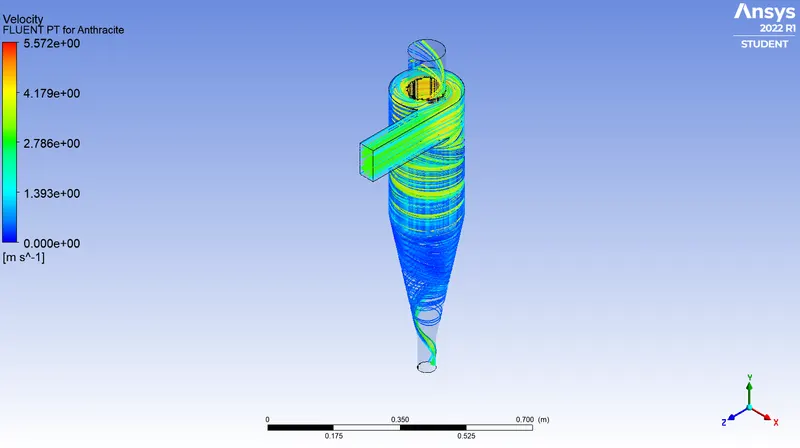
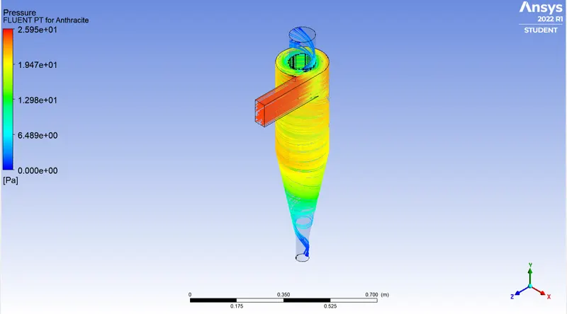
Case:1.2
- Velocity = 3m/s
- Size of particle = 2e-6 m
Residual
Velocity at Fluent PT for Anthracite
Pressure at Fluent PT for Anthracite
Particle time at Fluent PT for Anthracite
Velocity plane
Pressure plane
Case:1.3
- Velocity = 3m/s
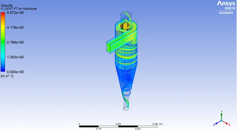
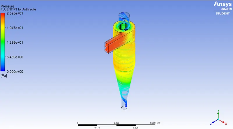
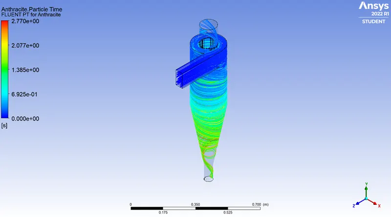
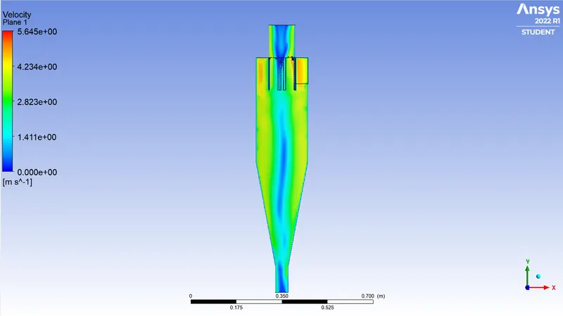
- Size of particle = 3e-6 m
Residual
Velocity at Fluent PT for Anthracite
Pressure at Fluent PT for Anthracite
Particle time at Fluent PT for Anthracite
Velocity plane
Pressure plane
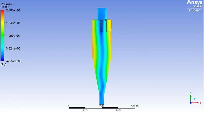
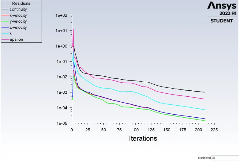
Case:1.4
- Velocity = 3m/s
- Size of particle = 4e-6 m
Residual
Velocity at Fluent PT for Anthracite
Pressure at Fluent PT for Anthracite
Particle time at Fluent PT for Anthracite
Velocity plane
Pressure plane
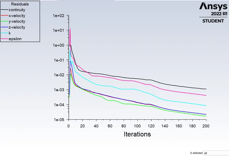
Case: 1.5
- Velocity = 3m/s
- Size of particle = 5e-6 m
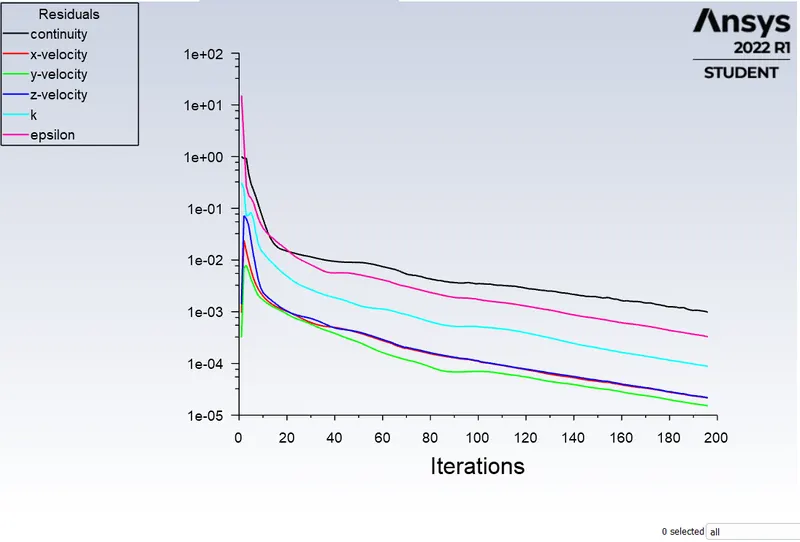
Residual
Velocity at Fluent PT for Anthracite
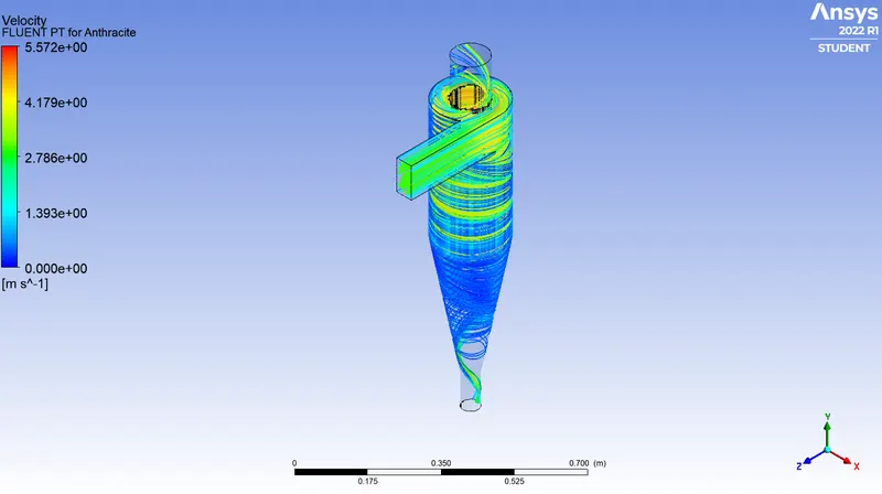
Pressure at Fluent PT for Anthracite
Particle time at Fluent PT for Anthracite
Velocity plane
Pressure plane
Case: 2.1
- Velocity = 1 m/s
- Size of particle = 5e-6 m
Residual
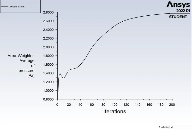
Inlet pressure
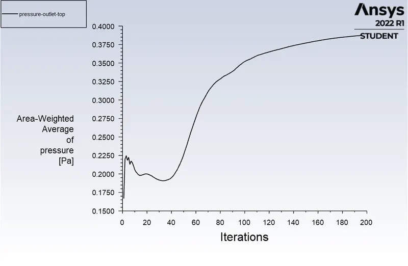
Outlet-top Pressure
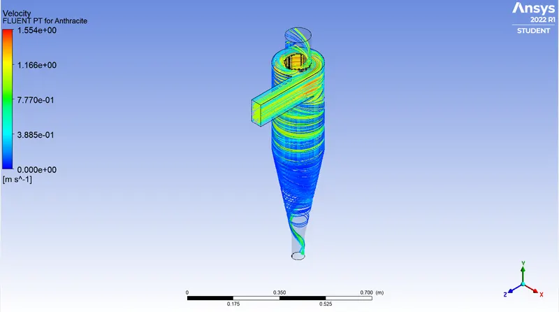
Velocity at Fluent PT for Anthracite
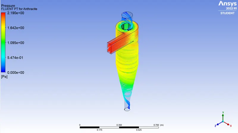
Pressure at Fluent PT for Anthracite
Particle time at Fluent PT for Anthracite
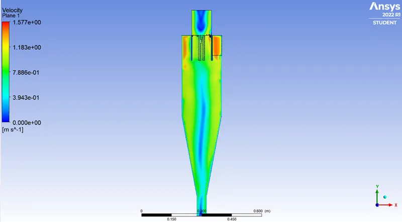
Velocity plane
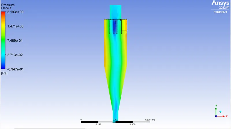
Pressure plane
Case: 2.2
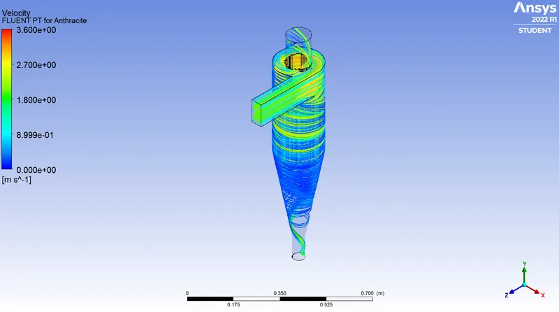
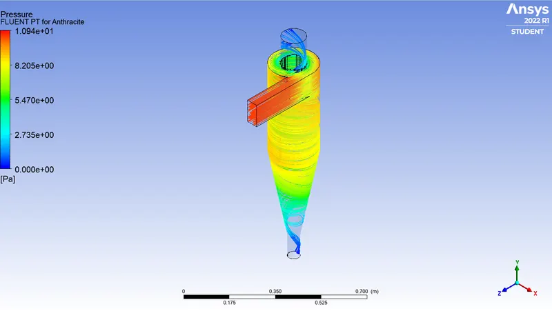
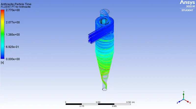
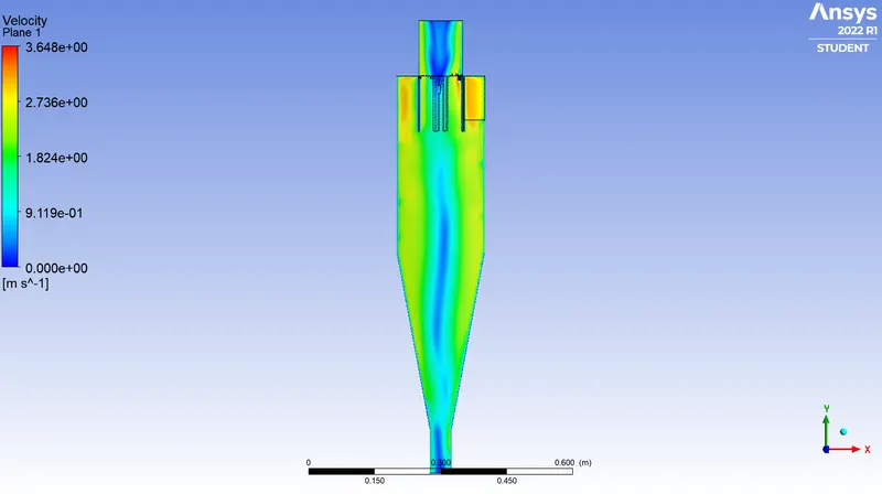
- Velocity = 2 m/s
- Size of particle = 5e-6 m
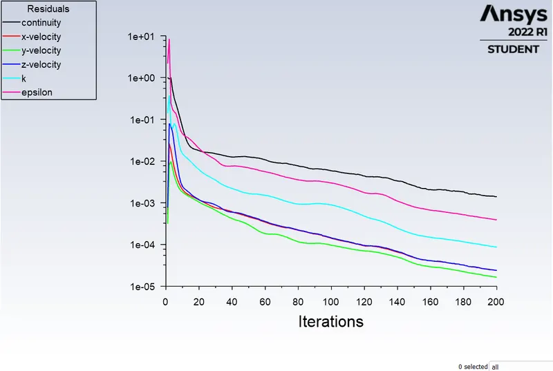
Residual
Velocity at Fluent PT for Anthracite
Pressure at Fluent PT for Anthracite
Particle time at Fluent PT for Anthracite
Velocity plane
pressure plane
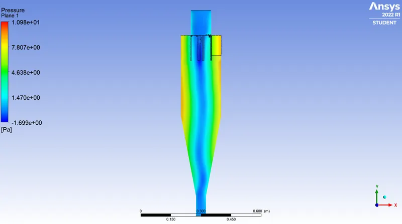
Case: 2.3
- Velocity = 3 m/s
- Size of particle = 5e-6 m
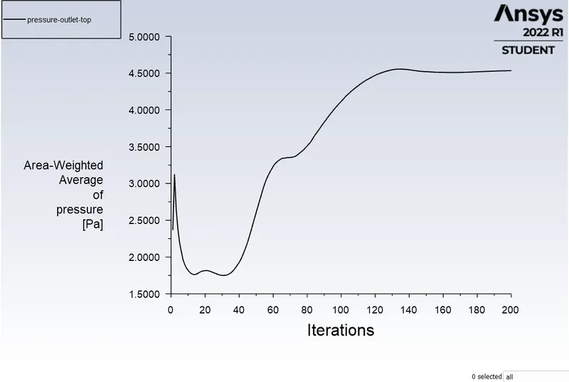
Residual
Inlet pressure
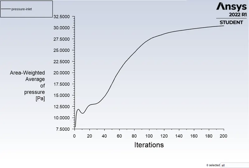
Outlet pressure
Velocity at Fluent PT for Anthracite
Pressure at Fluent PT for Anthracite
Particle time at Fluent PT for Anthracite
Velocity plane
Pressure plane
Case: 2.4
- Velocity = 4 m/s
- Size of particle = 5e-6
Residual
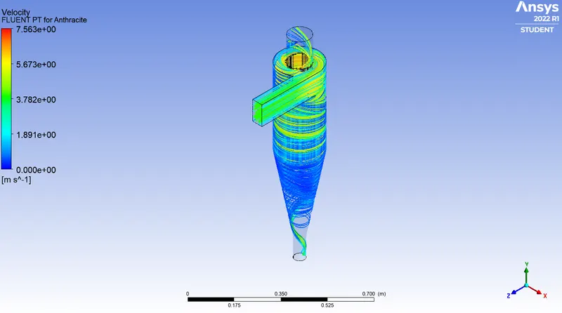
Velocity at Fluent PT for Anthracite
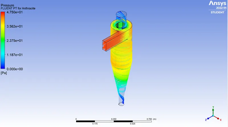
Pressure at Fluent PT for Anthracite
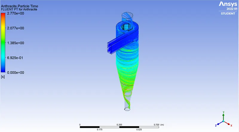
Particle time at Fluent PT for Anthracite
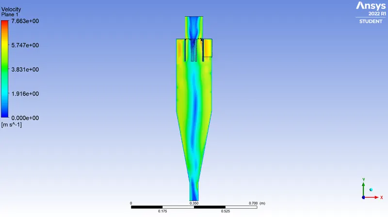
Velocity plane
Pressure plane
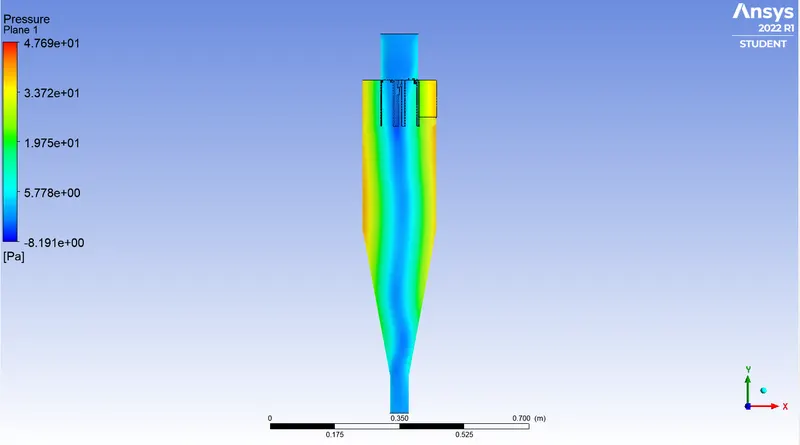
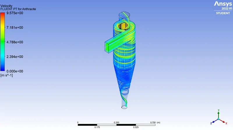
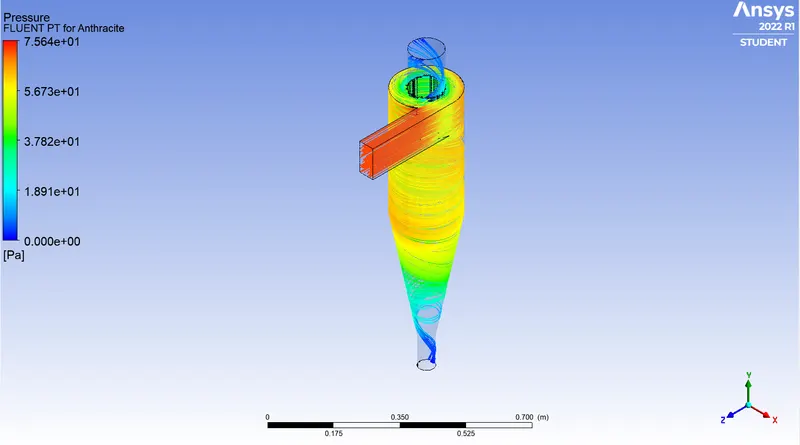
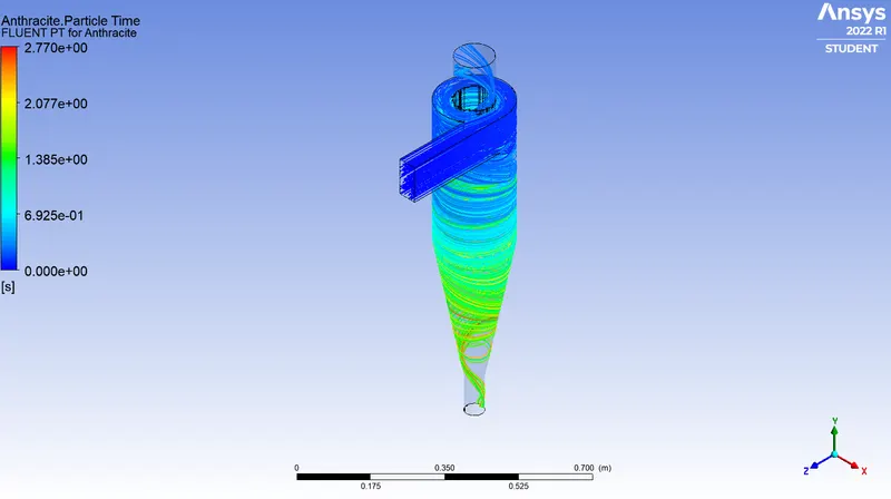
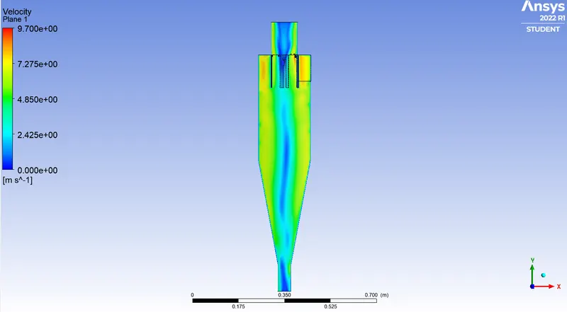
Case: 2.5
- Velocity = 5 m/s
- Size of particle = 5e-6 m
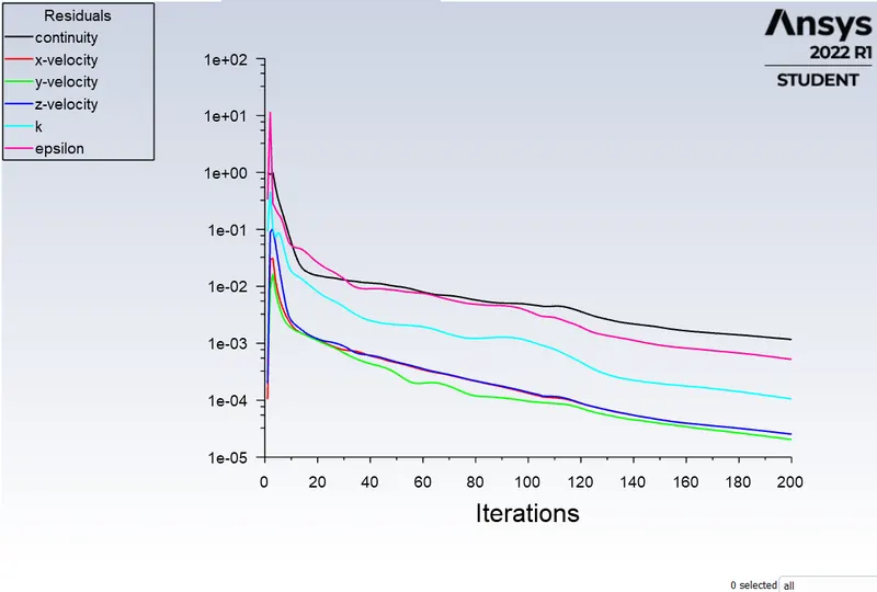
Residual
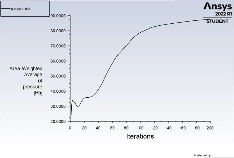
Inlet pressure
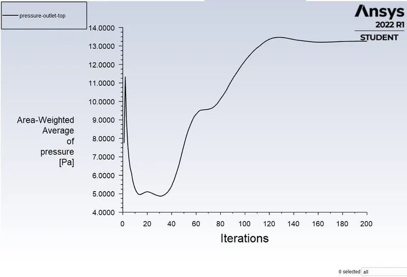
Outlet pressure
Velocity at Fluent PT for Anthracite
Pressure at Fluent PT for Anthracite
Particle time at Fluent PT for Anthracite
Velocity plane
Pressure plane
6.Comparision:
- Separation Efficiency = (Number of particles trapped/ Number of particle tracked)*100
- Pressure drop = Total inlet pressure - Total outlet pressure
Case:1
| case 1 numbers | Size of particle(m) | Velocity of particle (m/s) | Particle Tracked | Particle Trapped | Particle Escaped | Separation Efficiency | Pressure drop |
| 1. | 1e-6 | 3 | 378 | 304 | 73 | 80.4 | 25.869 |
| 2. | 2e-6 | 3 | 378 | 306 | 71 | 80.9 | 25.869 |
| 3. | 3e-6 | 3 | 378 | 301 | 76 | 79.62 | 25.869 |
| 4. | 4e-6 | 3 | 378 | 293 | 84 | 77.5 | 25.869 |
| 5. | 5e-6 | 3 | 378 | 312 | 66 | 82.53 | 25.869 |
- In this case 1, No change in pressure drop because There is no change in velocity.
Case:2
| case 1 numbers | Size of particle(m) | Velocity of particle (m/s) | Particle Tracked | Particle Trapped | Particle Escaped | Separation Efficiency | Pressure drop |
| 1. | 5e-6 | 1 | 378 | 301 | 72 | 79.6 | 2.3827 |
| 2. | 5e-6 | 2 | 378 | 299 | 73 | 79.1 | 11.07 |
| 3. | 5e-6 | 3 | 378 | 306 | 71 | 80.9 | 25.869 |
| 4. | 5e-6 | 4 | 378 | 311 | 67 | 82.2 | 46.928 |
| 5. | 5e-6 | 5 | 378 | 317 | 61 | 83.86 | 74.304 |
- In this case 2, Where the velocity is increased trapped particle also increased.
7.Conclusion:
- Efficiency of a cyclone separator has direct effect on the pressure drop.
- Higher efficiency cyclone separator has highest pressure drop.
- Higher the velocity, higher the pressure drop and highest the efficiency.