Week 8 - Simulating Cyclone separator with Discrete Phase Modelling
Aim :
To perform analysis on cyclone separator and calculate the separation efficiency and pressure drop
Introduction :
A cyclone separator is a device that is used to separate small particles that are in a flow of relatively large particles. In this there are 2 flows, One is the continuous flow which consists of the large particles and the other one is the discrete flow which is the flow of small particles which need to be removed. The given cyclone separator has 1 inlet and 2 outlets for the 2 phases.
Theory :
Empirical model for cyclone separator efficiency
- Iozia and Leith model
In this model, the efficiency is given by
`eta_i=1/(1+(d_50/d)^beta)`
where d50 is the cyclone cut diameter and `beta` is the logistical slope parameter which is obtained from the statistical analysis of experimental data
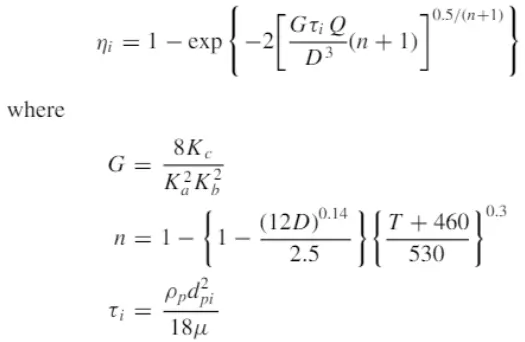
- Koch and Licht model
In this model, it is assumed that there is no slip in the tangential direction between the gas and the particle and the efficiency is given by
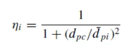
- Lapple model
In this model, it is assumed that a particle entering the cyclone separator is evenly distributed across the inlet area. The efficiency is given by
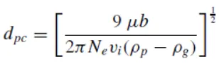
Where the half cut diameter is given by
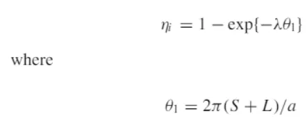
- Li and Wang model
In this model it is assumed that the radical particle velocity and radical concentration profile are not constant and the tagential velocity is related to the cyclone radius by `uR^n=`constant. Efficiency is given by
Pre-processing :
Geometry
The given cyclone separator model is loaded into spaceclaim
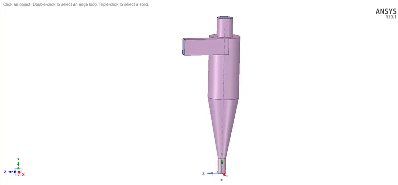
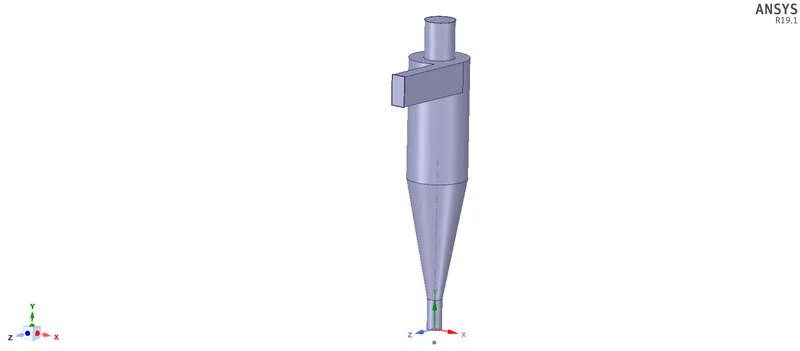
Using the volume extract option we select only the flow volume and suppressing the solid volume for analysis
Meshing
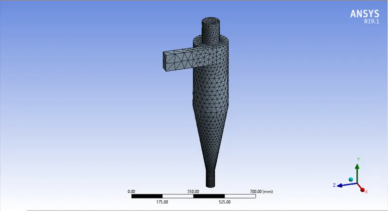
The base mesh is generated
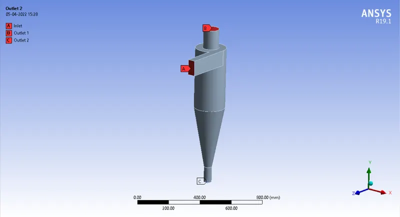
Named selections are created for the inlet and 2 outlets
Setup :
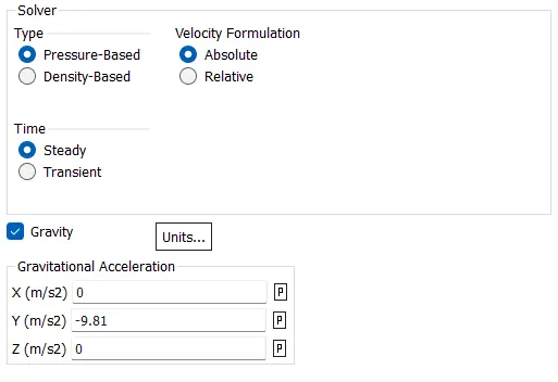
Gravity is enabled and the value is given in the negative y-direction, Steady-state simulation is perfomed
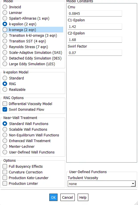
For the model, we selected k-epsilon RNG model with swirl dominated flow
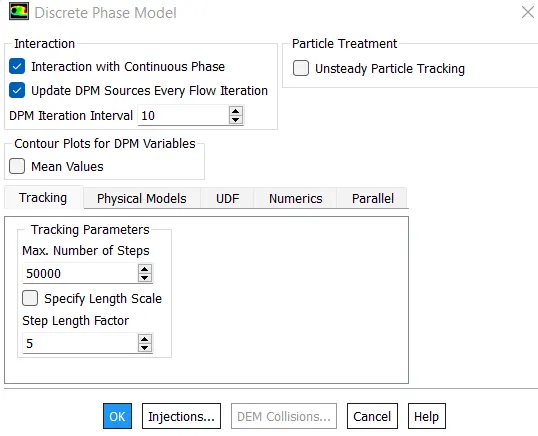
The Discrete phase model is selected and we do for combined flow and the number of steps are default
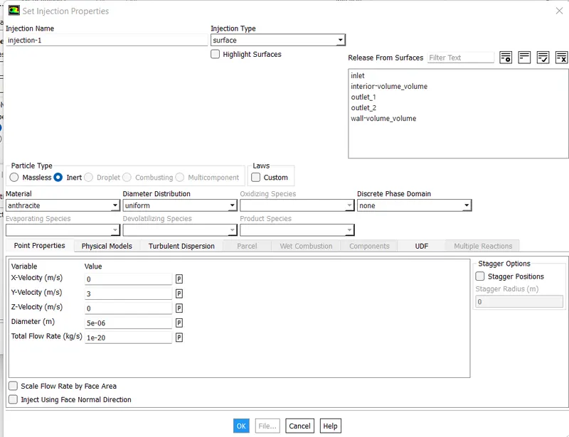
For injection, we go with anthracite material and injection type as inert
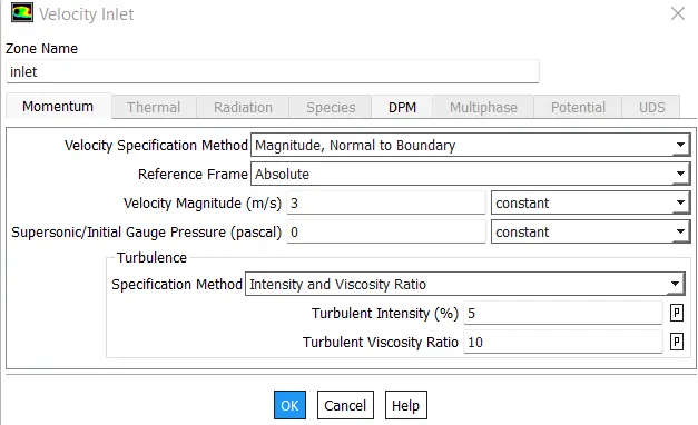
In boundary conditions for the inlet, we give the velocity of the particle and set the DPM to reflect
For the top outlet, DPM was set to escape
For the bottom outlet, DPM was set to trap
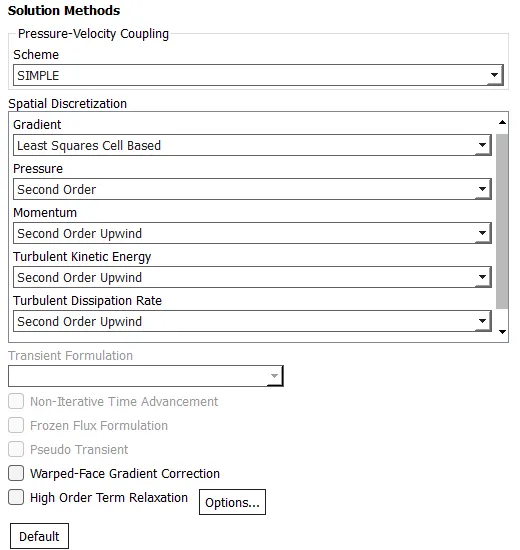
We select second-order upwind in solution methods
Results:
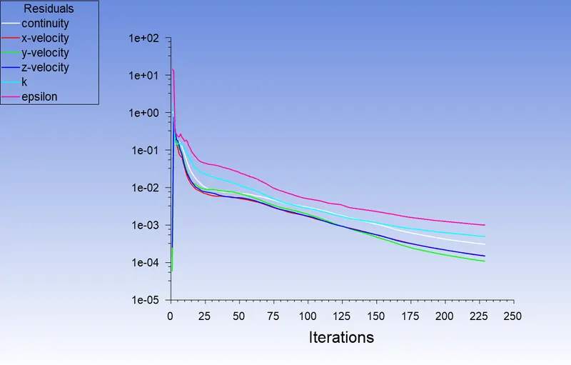
Residual plot
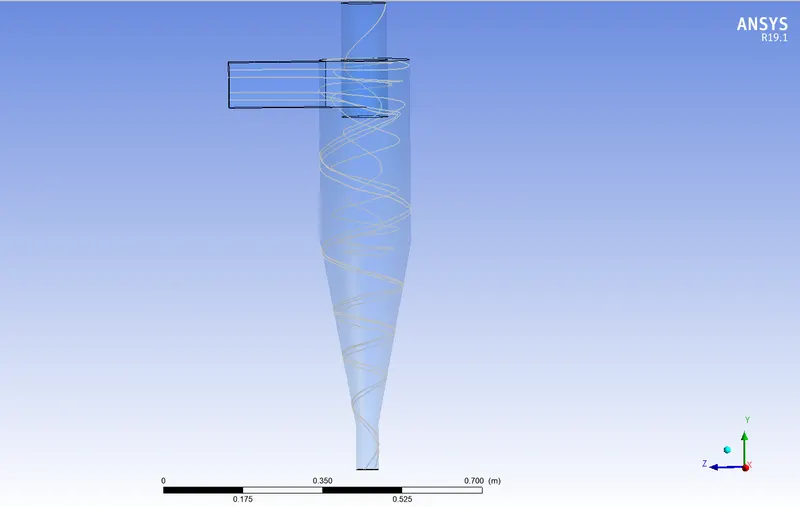
We could only track 4 particles so we have refine our mesh with element size = 10 mm
Refined mesh
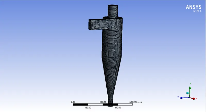
Size of particles (particle velocity - 3 m/s)
Particle size - 5 `mum`
Residual plot
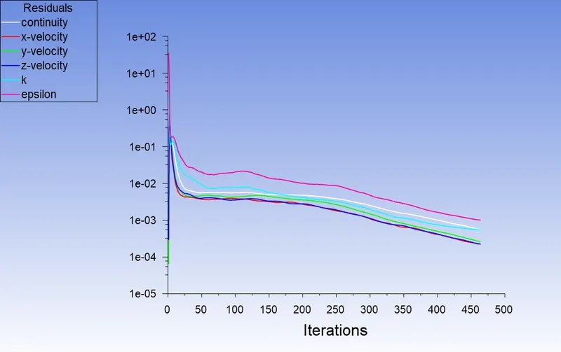
number tracked = 120, escaped = 6, aborted = 0, trapped = 111, evaporated = 0, incomplete = 3, incomplete_parallel = 0
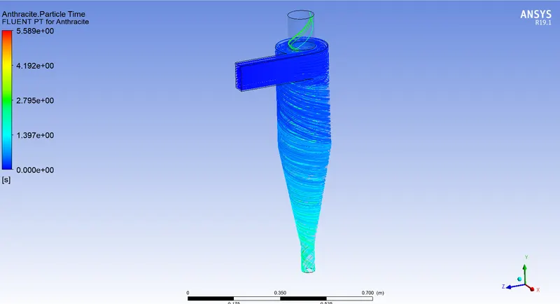
Separation efficiency = `("Number of particles trapped")/("Number of particles tracked")=111/120=0.925=92.5%`
Particle size - 2.5 `mum`
Residual plot
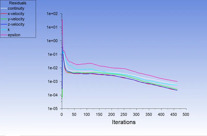
number tracked = 120, escaped = 26, aborted = 0, trapped = 92, evaporated = 0, incomplete = 2, incomplete_parallel = 0
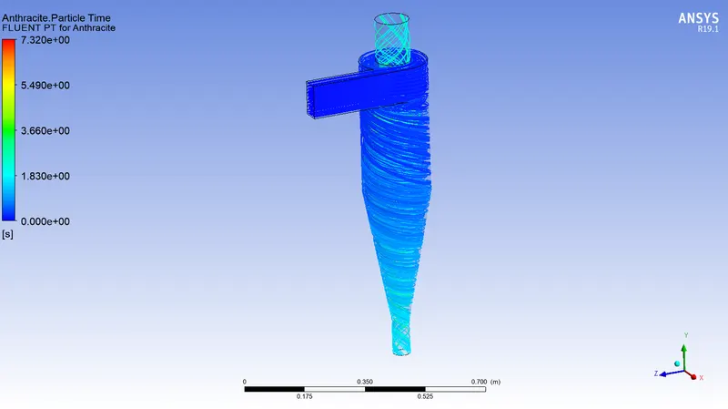
Separation efficiency = `("Number of particles trapped")/("Number of particles tracked")=92/120=0.767=76.7%`
Particle size - 1 `mum`
Residual plot
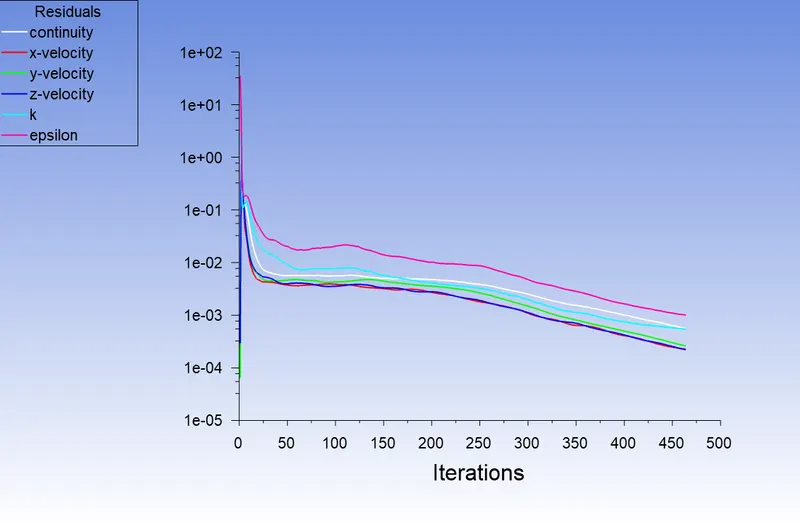
number tracked = 120, escaped = 38, aborted = 0, trapped = 30, evaporated = 0, incomplete = 52, incomplete_parallel = 0
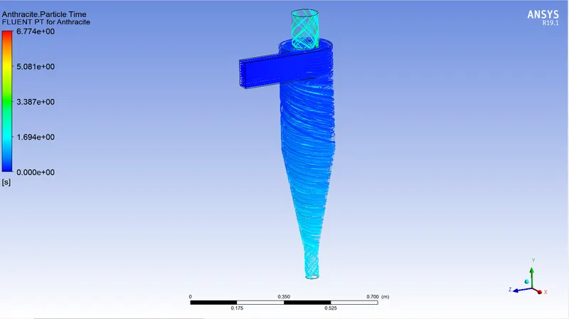
Separation efficiency = `("Number of particles trapped")/("Number of particles tracked")=30/120=0.25=25%`
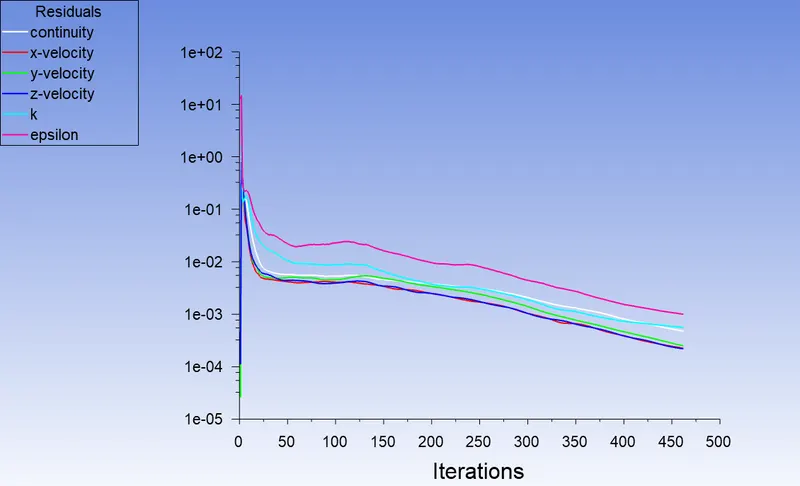
Velocity of the particles (size = 5 `mum`)
Particle velocity - 5 m/s
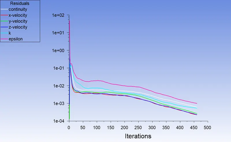
Residual plot
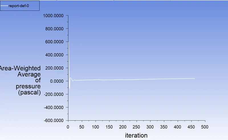
Pressure at inlet
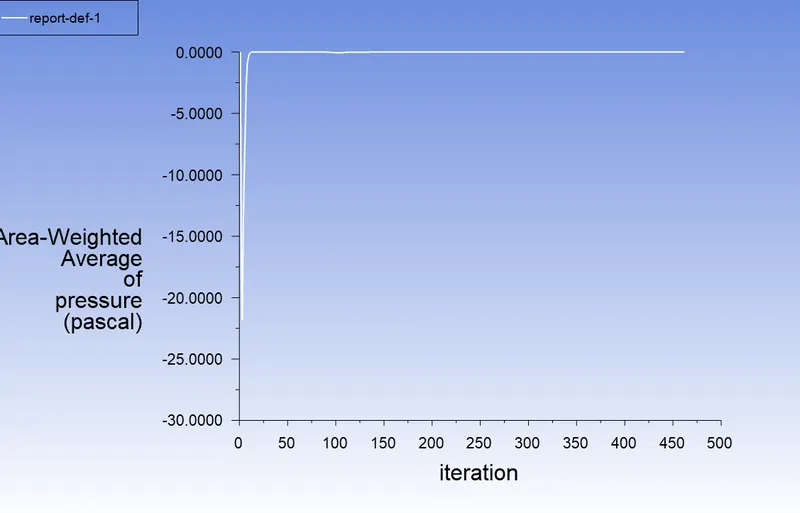
Pressure at outlet
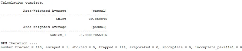
Separation efficiency = `("Number of particles trapped")/("Number of particles tracked")=119/120=0.992=99.2%`
Pressure drop = `"Pressure at inlet"-"Pressure at outlet"=39.859 Pa`
Particle velocity - 2.5 m/s
Residual plot
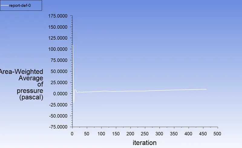
Pressure at inlet
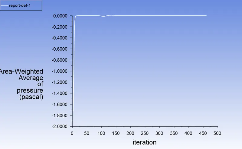
Pressure at outlet
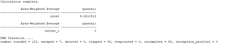
Separation efficiency = `("Number of particles trapped")/("Number of particles tracked")=55/120=0.458=45.8%`
Pressure drop = Pressure at inlet-Pressure at outlet=9.521 Pa
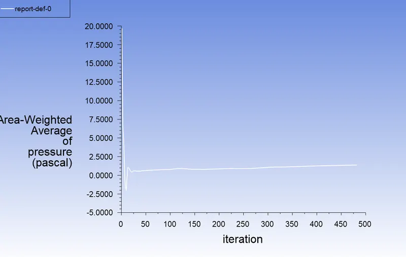
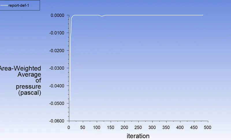
Particle velocity - 1 m/s
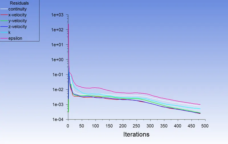
Residual plot
Pressure at inlet
Pressure at outlet
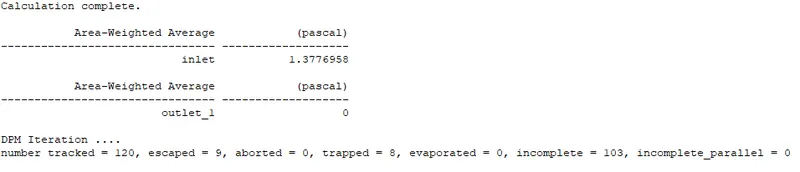
Separation efficiency = `("Number of particles trapped")/("Number of particles tracked")=8/120=0.067=6.67%`
Pressure drop = Pressure at inlet-Pressure at outlet=1.377 Pa
Conclusion :
Particle size vs Separation efficiency
| Particle size (`mum`) | Separation efficiency (%) |
| 5 | 92.5 |
| 2.5 | 76.7 |
| 1 | 25 |
So from the above results, we can say that as the size of the particle decreases the separation efficiency also decreases that too after 2.5`mum` the drop is high so we can say that this model of the cyclone separator has a good efficiency for particle size above 2.5`mum`
Particle velocity vs Separation efficiency vs Pressure drop
| Particle velocity (m/s) | Separation efficiency (%) | Pressure drop (Pa) |
| 5 | 99.2 | 39.859 |
| 2.5 | 45.8 | 9.521 |
| 1 | 6.67 | 1.377 |
So from the above results, we can also say that as the velocity of the particle decreases the separator efficiency decreases, and also the pressure drop is decreasing. Since the drop is high at 2.5m/s we can say that the optimal velocity that should be used is above 3 m/s