Week 8 - Simulating Cyclone separator with Discrete Phase Modelling
CYCLONE SEPARATOR
Cyclone separators provide a method of removing particulate matter from air or other gas streams at low cost and low maintenance. Cyclones are somewhat more complicated in design than simple gravity settling systems, and their removal efficiency is much better than that of settling chamber. Cyclones are basically centrifugal separators, consists of an upper cylindrical part referred to as the barrel and a lower conical part referred to as cone.
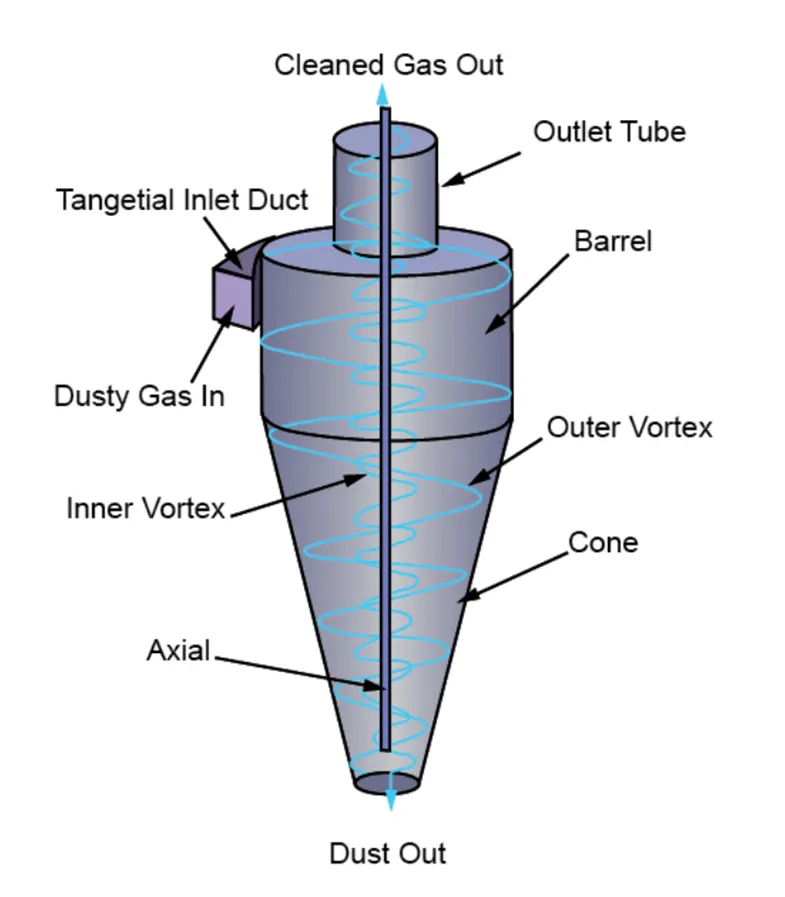
They simply transform the inertia force of gas particle flows to a centrifugal force by means of a vortex generated in the cyclone body. The particle laden air stream enters tangentially at the top of the barrel and travels downward into the cone forming an outer vortex. The increasing air velocity in the outer vortex results in a centrifugal force on the particles separating them from the air stream. When the air reaches the bottom of the cone, it begins to flow radially inwards and out the top as clean air/gas while the particulates fall into the dust collection chamber attached to the bottom of the cyclone.
These types of cyclones have a distinctive and easily recognized form and widely used in power and cement plants, feed mills and many other process industries.
The collection efficiency of cyclones varies as a function of density, particle size and cyclone design. Cyclone efficiency will generally increase with increases in particle size and/or density; inlet duct velocity; cyclone body length; number of gas revolutions in the cyclone; ratio of cyclone body diameter to gas exit diameter; inlet dust loading; smoothness of the cyclone inner wall.
Similarly, cyclone efficiency will decrease with increases in the parameters such as gas viscosity; cyclone body diameter; gas exit diameter; gas inlet duct area; gas density; leakage of air into the dust outlet. The efficiency of a cyclone collector is related to the pressure drop across the collector. This is an indirect measure of the energy required to move the gas through the system. The pressure drop is a function of the inlet velocity and cyclone diameter.
Collection efficiency
The collection or separation efficiency is most properly defined for a given particle size. As mentioned, fractional efficiency is defined as the fraction of particles of a given size collected in the cyclone, compared to those of that size going into the cyclone. Basically it is the ratio of particles trapped to the particles tracked.
Several equations have been developed to predict the collection efficiency in cyclones through correlation equations.
1. Iozia and Leith Model
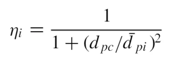
The model assumes that a particle carried by the vortex endures the influence of two forces: a centrifugal force and a flow resistance. The collection efficiency of particle diameter dpi can be calculated from
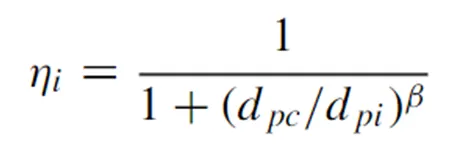
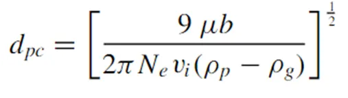
dpc is the cut-diameter given by
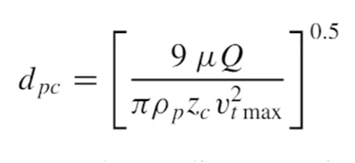
The cut diameter of the cyclone is defined as the size of the particles collected with 50% collection efficiency.
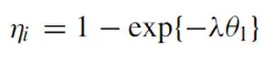
2. Li and Wang model
This model includes particle bounce or reentrainment and turbulent diffusion at the cyclone wall.
The radial particle velocity and the radial concentration profile are variable for uncollected particles within the cyclone.
The tangential velocity is related to the radius of cyclone by uR^n = constant.
3. Koch and Licht model
The Kock and Licht collection theory recognized the inherently turbulent nature of the cyclones and the distribution of gas residence times within the cyclone. Following assumptions were used to describe the particle motion in the entry and collection regions.
The tangential velocity of a particle is equal to the tangential velocity of the gas flow i.e. there is no slip in the tangential direction between the particle and the gas.
The tangential velocity is related to the radius of cyclone by uR^n = constant.
4. Lapple
This model was developed without considering the flow resistance. Lapple assumed that a particle entering the cyclone is evenly distributed across the inlet opening. The particle that travels from inlet half width to the wall in the cyclone is collected with 50% efficiency. The 50% cut diameter and the collection efficiency is given by, half width to the wall in the cyclone is collected with 50% efficiency. The 50% cut diameter and the collection efficiency is given by,
OBJECTIVES
- Explain the working of cyclone separator, methods to evaluate its efficiency and its practical importance and applications.
- Simulate the working of cyclone separator in Ansys Fluent using suitable models for the flow occurring within.
- To perform analysis on a given cyclone separator by varying flow parameters such as the particle diameter, particle velocity and evaluate the separation efficiency for each case.
- Discuss the results and inferences based on the results.
SOLVING & MODELLING APPROACH
Cyclones are basically centrifugal separators. They simply transform the inertia force of gas particle to a centrifugal force by means of a vortex generated in the cyclone body. The gas with particles enters tangentially at the upper part and passes through the body describing the vortex. Particles are driven to the wall by centrifugal forces, lose the momentum and fall into the cyclone leg. In lower section, the gas begins to flow radially inwards to the axis and spins upwards to the gas outlet duct.
The particles in the system experience changes in their momentum due to interaction with the separator geometry as well as they exchange momentum, energy and mass with the gas. The interaction with the gas phase might be in terms of buoyancy, drag or viscous forces. To model this effectively, the Discrete Phase Modelling in Ansys Fluent is chosen.
GEOMETRY & MESH
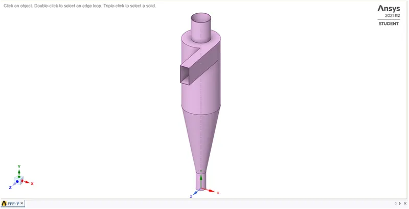
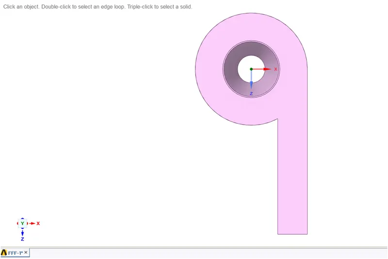
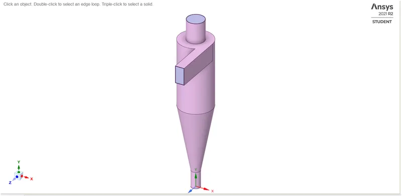
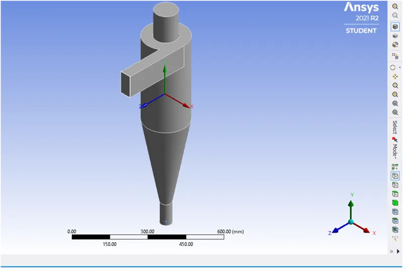
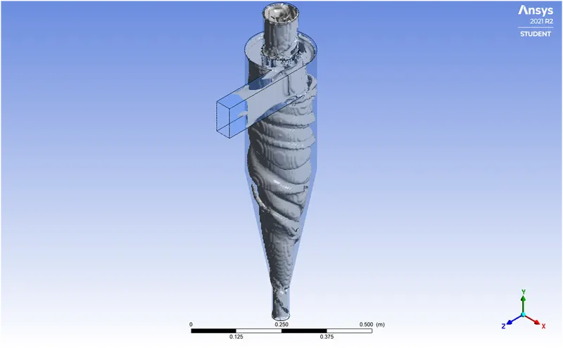
The model has a tangential entry duct at the top through which particle laden gas enters the separator. There are two outlets, one at the top & other at the bottom. Particles are trapped in the bottom outlet whereas gas excapes through the top outlet. The vortex is generated in the barrel & the cone.
Cyclone separator model Top view
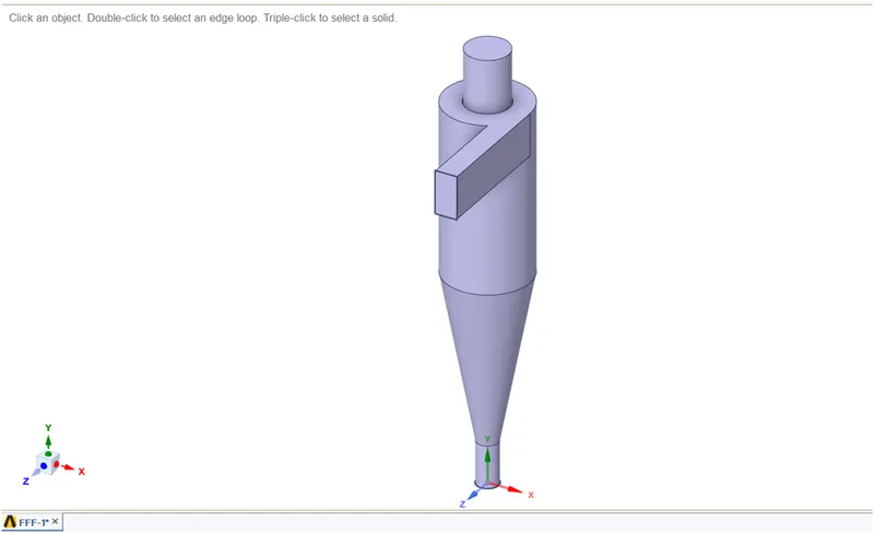
The Volume extract option in SpaceClaim is used to extract the internal fluid volume of the cyclone separator geometry.
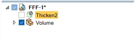
Fluid volume extracted Fluid volume
MESH
Element size
Global: - 10 mm
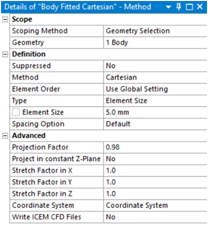
Body fitted Cartesian: - 10 mm
Element count
Nodes: - 452919
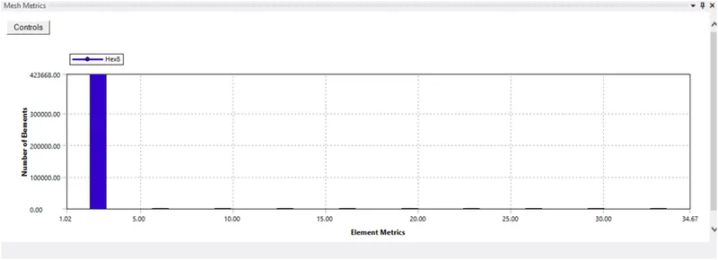
Elements: - 424458
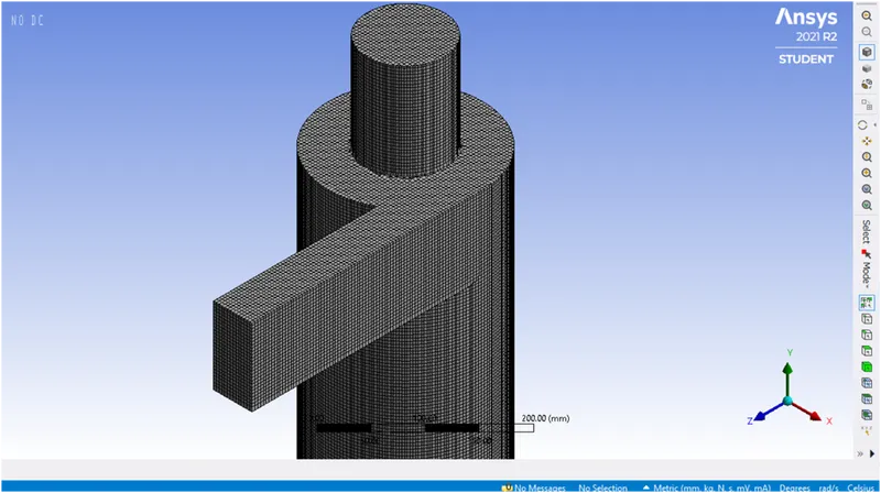
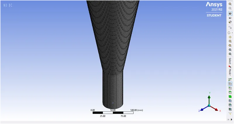
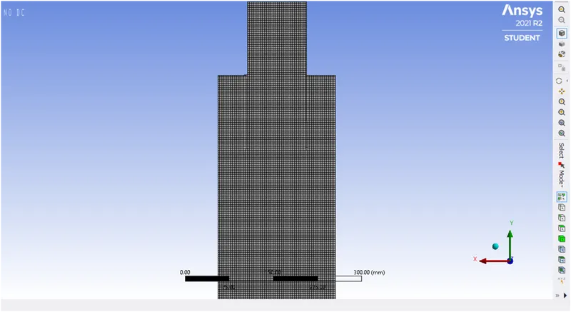
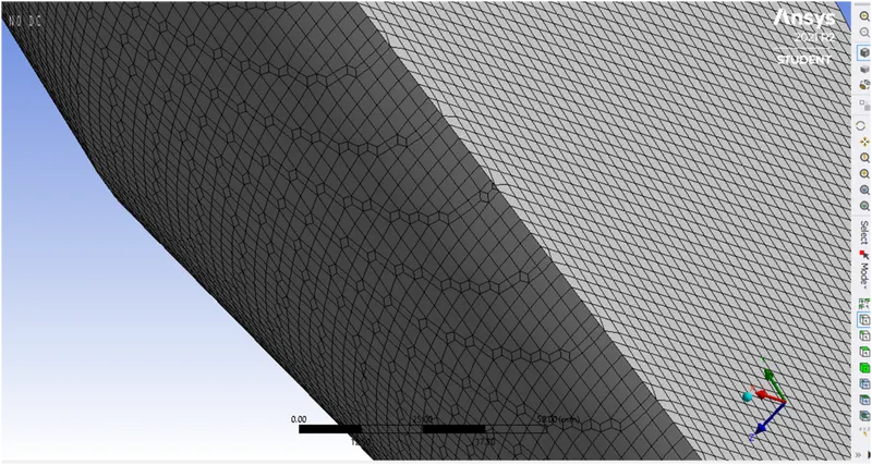
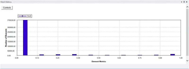
A body fitted Cartesian mesh method is used to create mesh. This method creates mesh with hexahedral elements. The hexahedral elements have the highest quality among all element types & give the most accuracy of solutions. The Cartesian mesh is generated using the coordinates of the Centroid of the model.
Skewness Aspect ratio
SOLVER REQUIREMENTS
As discussed earlier, the Discrete Phase Modelling approach is used to simulate flow in the cyclone separator. This model follows the Euler-Lagrange approach. The fluid phase is treated as a continuum by solving the Navier-Stokes equations, while the discrete phase is solved by tracking a large number of particles.
It is assumed that the dispersed second phase occupies a low volume fraction. The particle trajectories are computed at specified intervals. Fluent predicts the particle trajectory by integrating the force balance on the particle, which is written in Lagrangian frame.
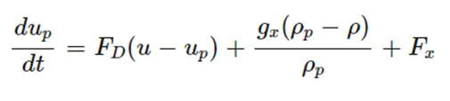
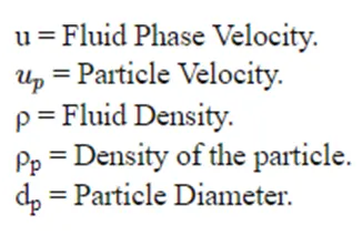
The coupling between the continuous and the discrete phase is done using two-way coupling. The continuous phase influences the discrete phase via drag and turbulence. The discrete phase via source terms of mass, momentum and energy.
The tracking parameters used to control the time integration of particle trajectory equation are;
Maximum number of steps: - Imposes a limit on the number of timesteps to avoid the possibility of a particle being trapped in a recirculating region of the continuous phase. If the particle never exits the flow, it is reported as ‘incomplete’.
Length scale & Step length factor: - The integration time step is computed based on a specified length scale & the velocity of particle & continuous phase. It is equivalent to the distance that the particle will travel before its motion equations are solved again & its trajectory updated.
The step length factor allows Fluent to compute the time step in terms of the number of time steps required for a particle to traverse a computational cell. One thumb rule to follow is, if a particle is to advance through N mesh cells in main flow direction, the step length factor times N should be approx equal to the max number of steps.
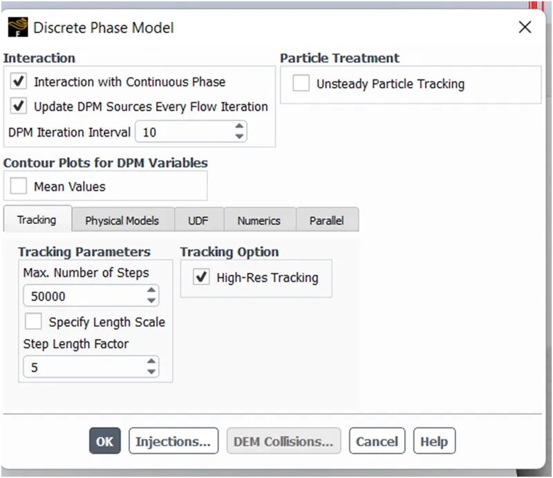
The DPM iteration interval is the frequency with which the particles are tracked and the sources are updated.
Boundary Conditions
Inlet & wall: - Reflect
The particles are reflected via an elastic or inelastic collision with the wall.
Outlet (top): - Escape
The particle escapes from the boundary and is lost from the calculation when it impacts the boundary.
Outlet (bottom/dustbin): - Particle is trapped at the wall & lost from the calculation the moment it impacts the wall.
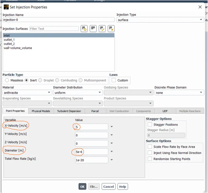
The injection properties set the injection surfaces and particle velocities at the surface. The x-velocity is defined from the local coordinate system at the surface.
The diameter is the particle size in micro-meter.
RESULTS
Case 1] The simulation is run for the model by varying the particle size from 1um to 5 um while the particle and continuous phase velocity is kept 3 m/s for both. The separation efficiency is determined for each particle size. The particle size chosen are 1um, 2.4 um, 5 um.
Case 2] Particle size is kept 5um while the particle velocity is varied from 1 m/s to 5 m/s. The simulation is run for particle velocities 1 m/s, 3 m/s, 5 m/s. The separation efficiency and pressure drop is determined for each particle velocity.
Case 1] Same velocity different size.
1) Comparison between 1 um & 2.4 um.
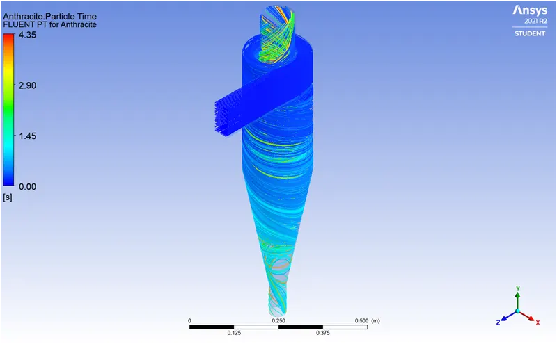
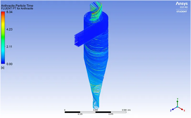
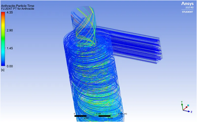
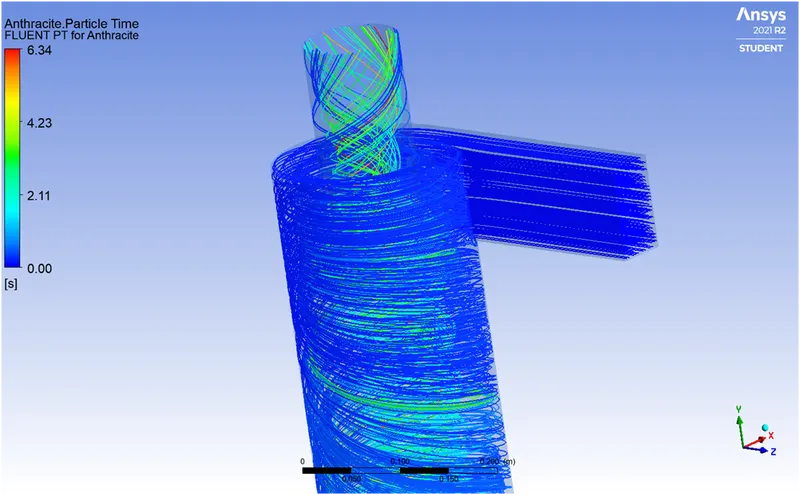
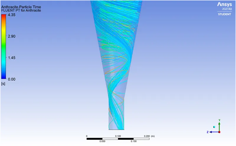
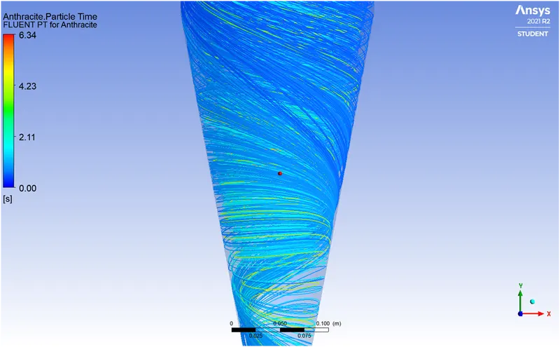
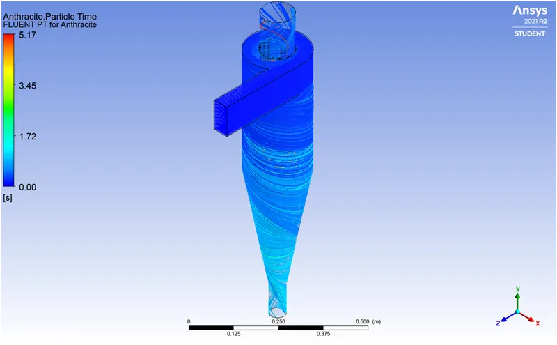
Paritcle Time
1um 2.4 um
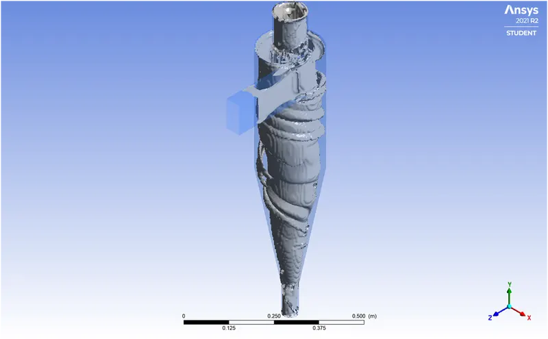
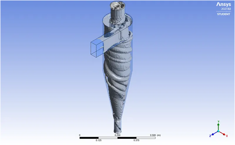
Vortex core Region
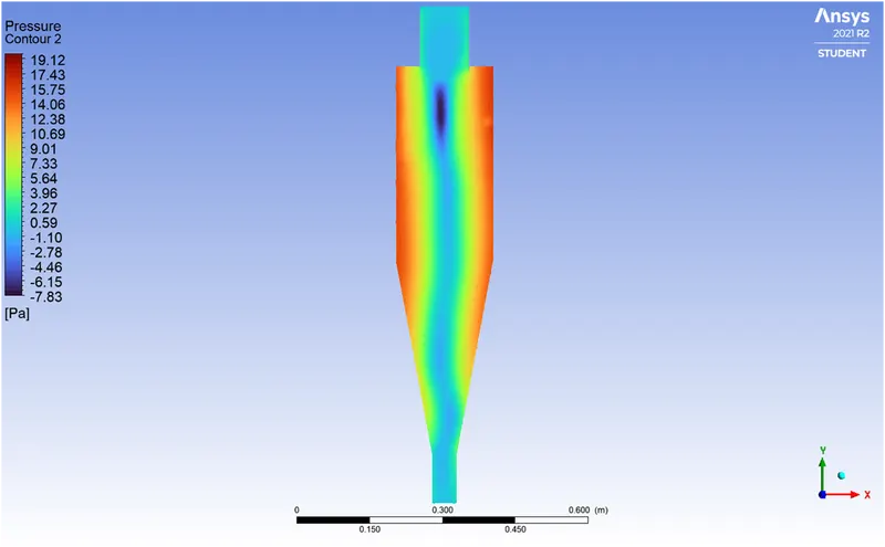
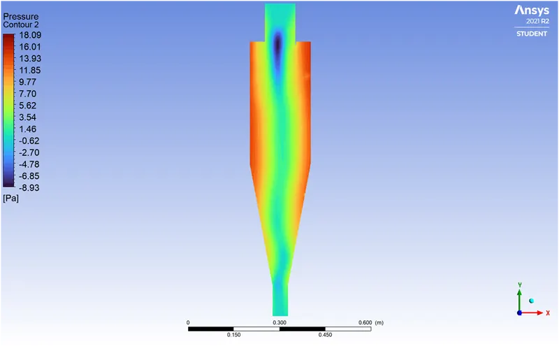
Pressure contour
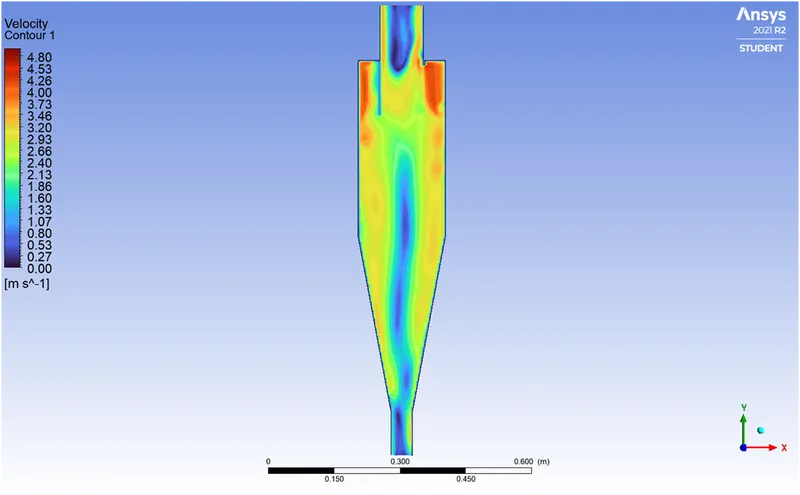
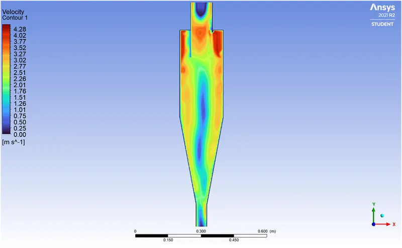
Velocity contour


INFERENCES
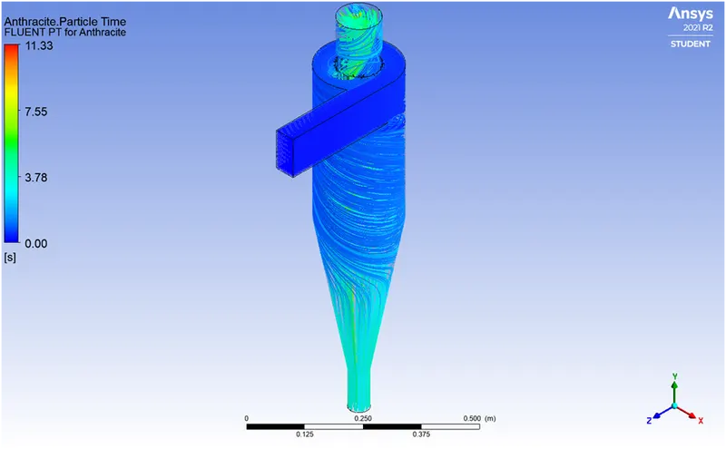
- From the particle time contour, the particles in the outer vortex spend less time inside as compared to those trapped inside the inner vortex.
- The amount of particles that escaped are greater for 1 um than 2.4 um. Hence, larger particle size improve the efficiency.
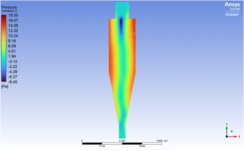
- A low pressure zone is created in the central part of the separator. As the particles slide down the cone some escape through this low pressure zone into the top outlet.
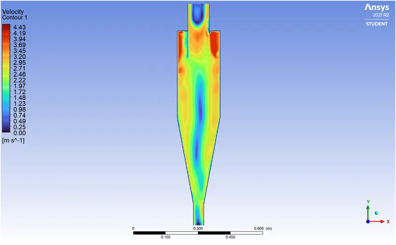
- The velocity contour is similar for both. The velocity is maximum near the inlet as seen in the plots indicated by 'red' colour.
2)Comparison between 2.4 um & 5 um.
2.4 um 5 um
Vortex core Region
Pressure contour
Velocity contour
Collection efficiency calculation
| particle size | inlet | outlet 1 | outlet 2 | collection efficiency |
| micro-meter | tracked | escaped | trapped | (trapped/tracked)*100% |
| 1 um | 378 | 147 | 231 | 61.11111111 |
| 2.4 um | 378 | 126 | 252 | 66.66666667 |
| 5 um | 378 | 60 | 318 | 84.12698413 |
With increase in particle size, the collection efficiency increases.
Case B] Same size different velocity.
1) Comparison between 1 m/s & 3 m/s
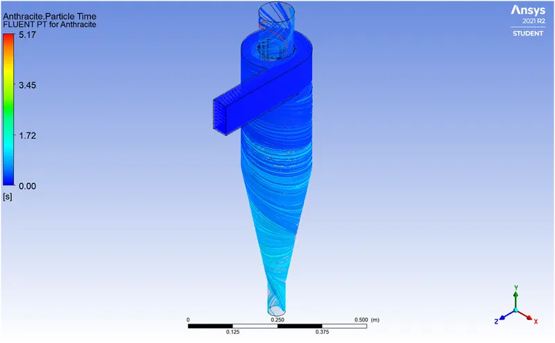
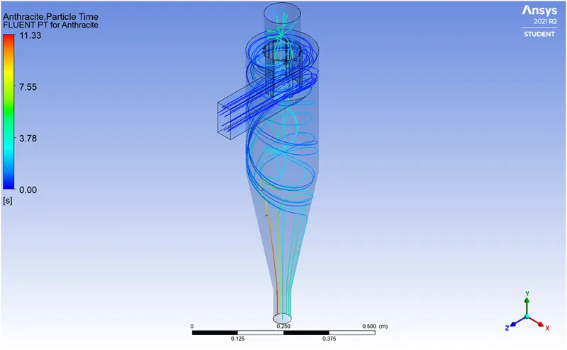
Particle time
1 m/s 3 m/s
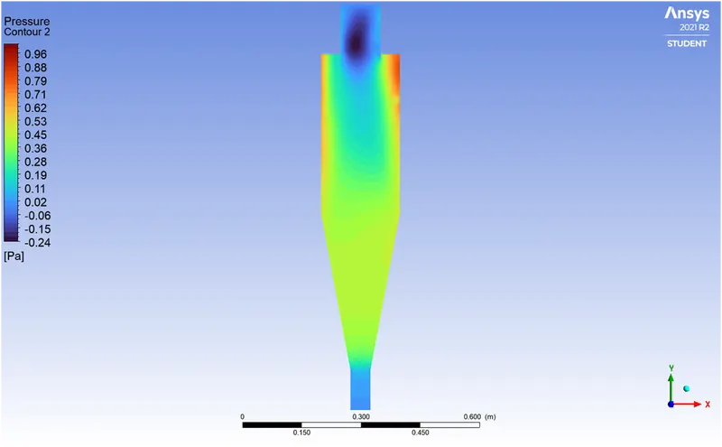
Pressure contour
Velocity contour
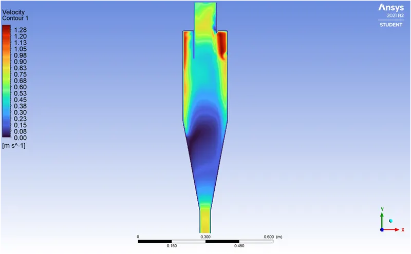
- For 1 m/s particle velocity, the vortex formed has lesser strength as compared to 3 m/s particle velocity. In fact, as the particles reach the cone, some drop straight down into the outlet 2 without following a curved trajectory.
- The pressure contour shows a uniform distribution in the barrel & cone section whereas a negative pressure zone at outlet 1 (top) for 1m/s particle velocity. This pressure gradient drives the particles towards the top at outlet 1.
1) Comparison between 3 m/s & 5 m/s
3 m/s 5 m/s
5 m/s
Pressure contour
Velocity contour
INFERENCES
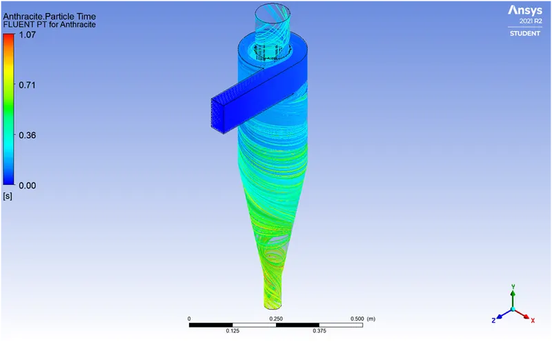
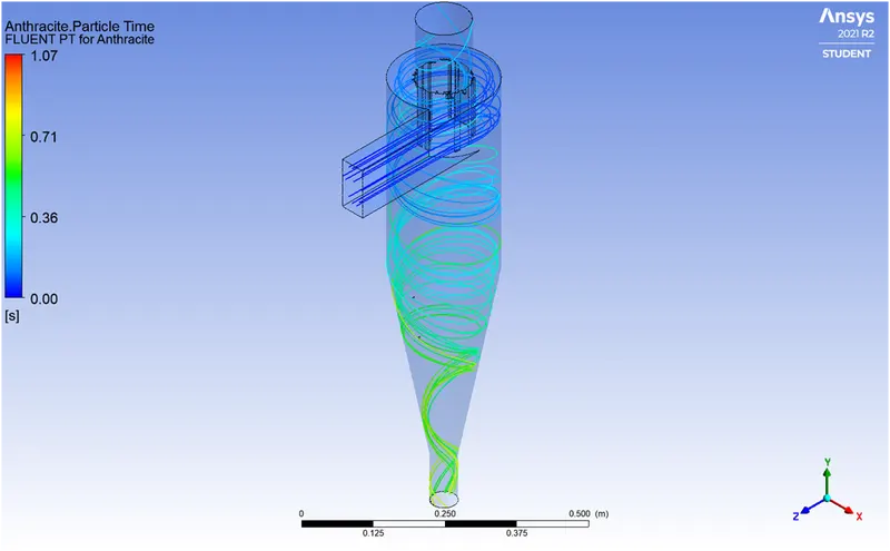
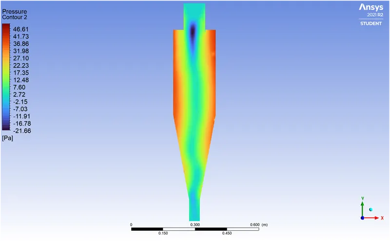
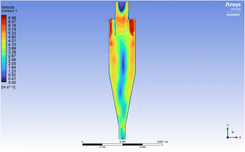
- As the velocity is increased the particle residual time reduces drastically. A negative pressure zone appears in the centre as the pressure radially towards the centre.
- A near perfect vortex is formed for 5 m/s particle velocity. The pressure drop for each particle velocity is,
| Particle velocity | Pressure at inlet | Outlet 1 (top) | Outlet 2 (bottom) | DelP bet inlet & outlet1 | DelP bet inlet & outlet2 |
| 1 m/s | 0.96 | -0.24 | 0.02 | 1.2 | 0.94 |
| 3 m/s | 18.55 | -8.45 | 1.04 | 27 | 17.51 |
| 5 m/s | 46.61 | -21.66 | 2.5 | 68.27 | 44.41 |
The pressure drop increases as well with increase in particle velocity.