Week 8 - Simulating Cyclone separator with Discrete Phase Modelling
AIM Studying Discrete Phase modelin using Cyclone Separator.
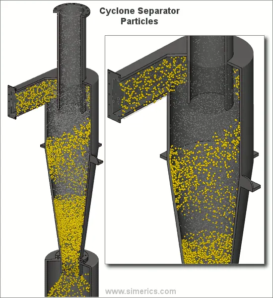
Introduction: A Cyclone separaor is a mechanical device which uses the centrifugal action of the flow to separate the suspended particles inside the fluid. For example, the flue gases are separated from the air using a cyclone separator in industry. Depending on the size of particles the cyclone separator varies in its inlet velocity, this leads to efficient separations. In this study an attempt is made to understand the separation efficiency using descrete phase modeling using ansys Fluent.
 |
Ways to calculate cyclone separator efficiency:
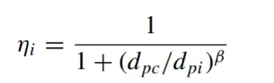
1) Iozia and Leith Model:
Based on force balance method. It assumes that the vortex experiences 2 forces, centrifugal and rsistance. Based on this the collection efficiency is calculated as:
 |
where,
 |
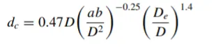
Here, the diameters are based on the geometry. Although, the relationship is a function of mass-flow rate and the velocity(maximum)
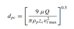 |
and
 |
2) Li and Wang model:
This model assumes a partial bounce or re-entrainment and turbulent diffusion at the wall. A 2D expression is given as.
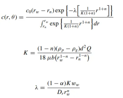 |
The efficeincy of the separator is then given by,
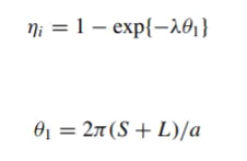 |
3) Koch and Licht Model:
Based on assumptions such as
a) The tangential velocity of a particle is equal to te tangential velocity of the gas flow.
b) The tangential velocity is related to the radius of cyclone by: `u*R^n = Constant`
As in the fist method this too, uses a force balance to evaluate the efficiency.
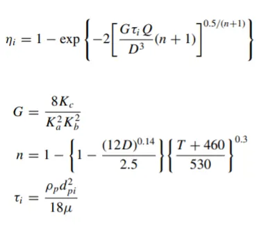 |
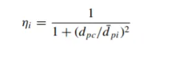
4) Lapple Model: As was the first model this is developed the same way but without considering the flow resistance. this model calculates the semi-emperical relationship as it is assumed that the particle entering te cyclone is evenly distributed across the inlet opening.
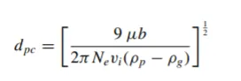 |
Where, efficiency is given by,
 |
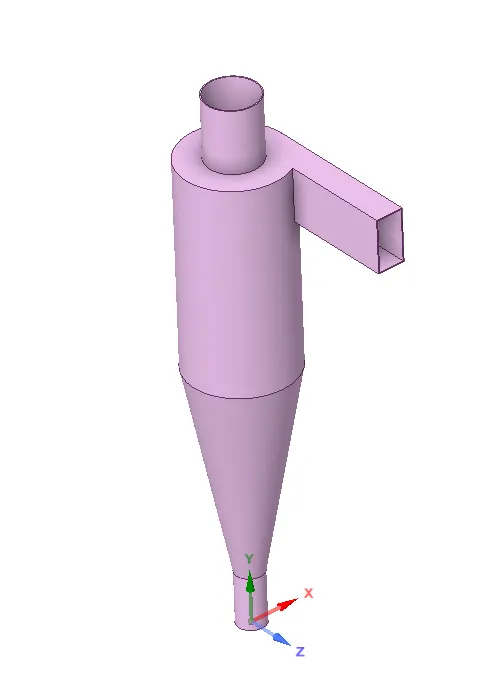
Geometry of Cyclone Separator
 |
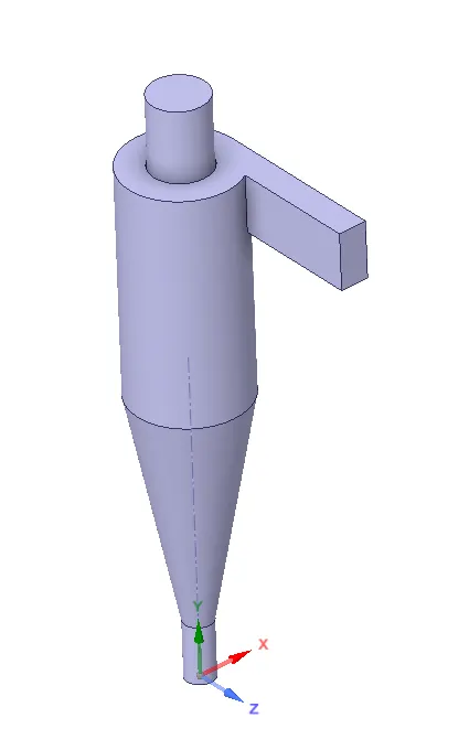
Fluid volume:
 |
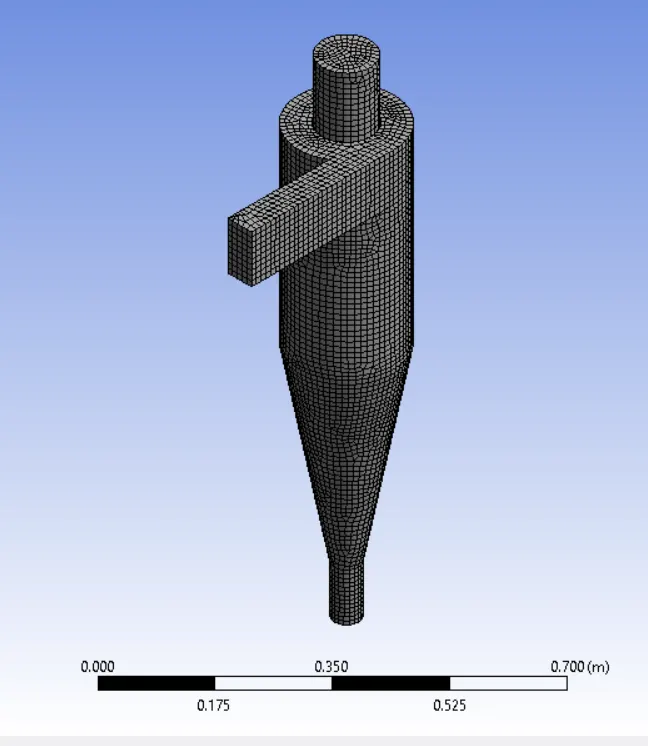
Meshing: Structured mesh
 |
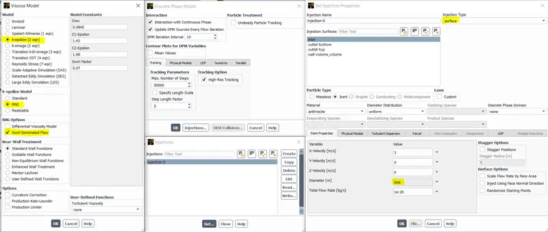
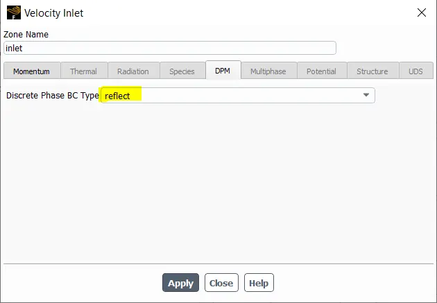
Setup: Discrete phase modeling.
Note: The size of the particles id parametrized for automation of the setup.
 |
 |
Result:
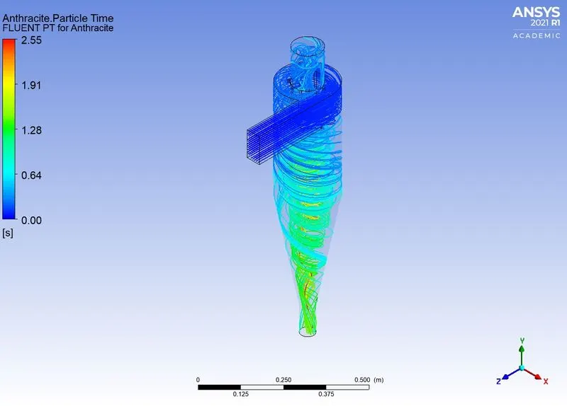
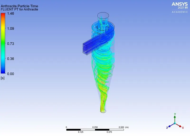
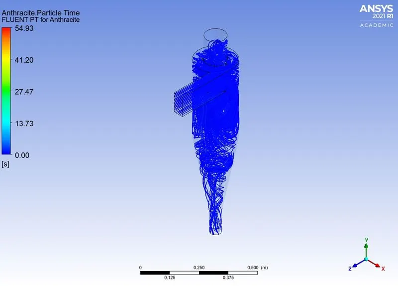
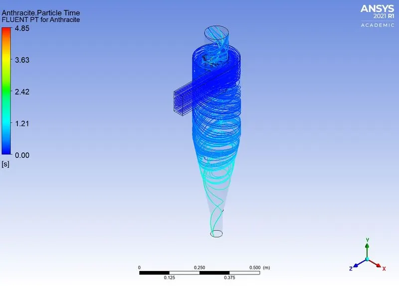
Case 1) For constant velocity with varying size of the partcles.
| Size | Velocity | Particle time |
| 1e-6 | 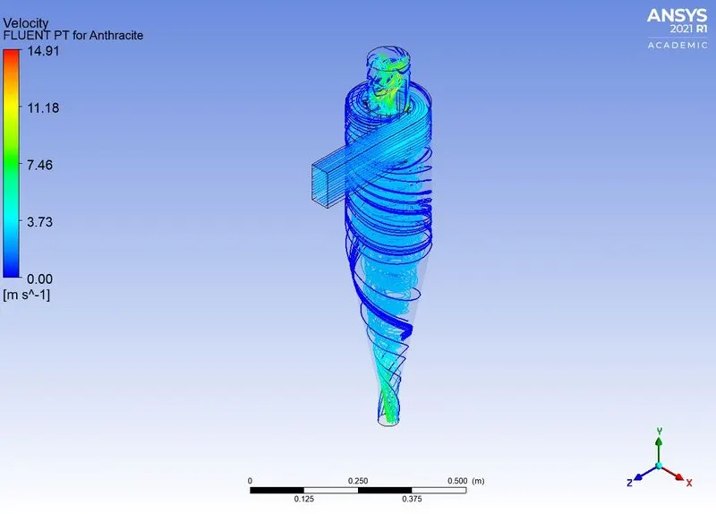 |
 |
| 2e-6 | 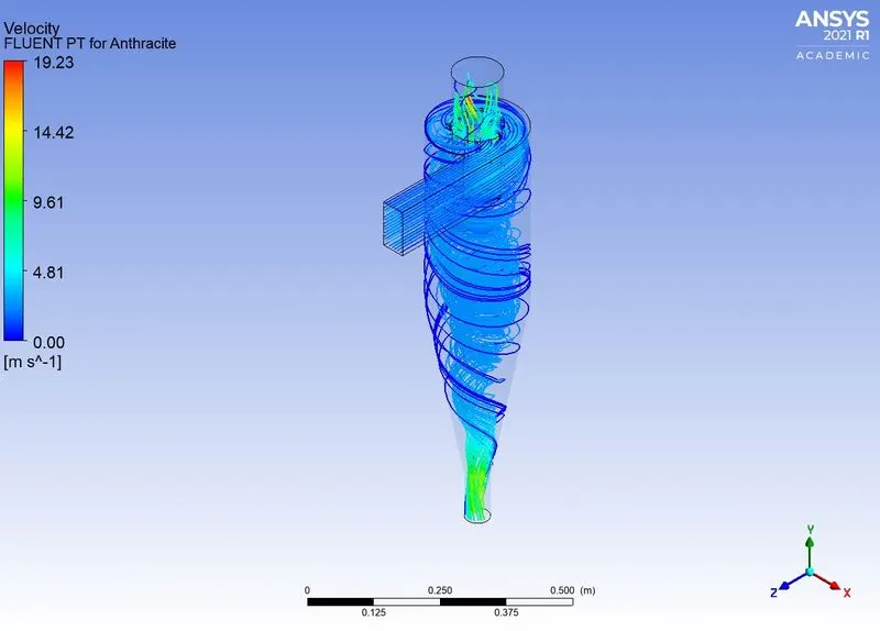 |
 |
| 3e-6 | 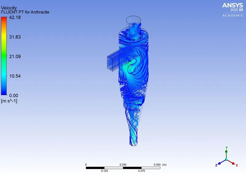 |
 |
| 4e-6 | 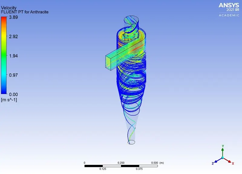 |
 |
| 5e-6 | 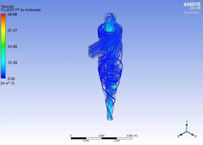 |
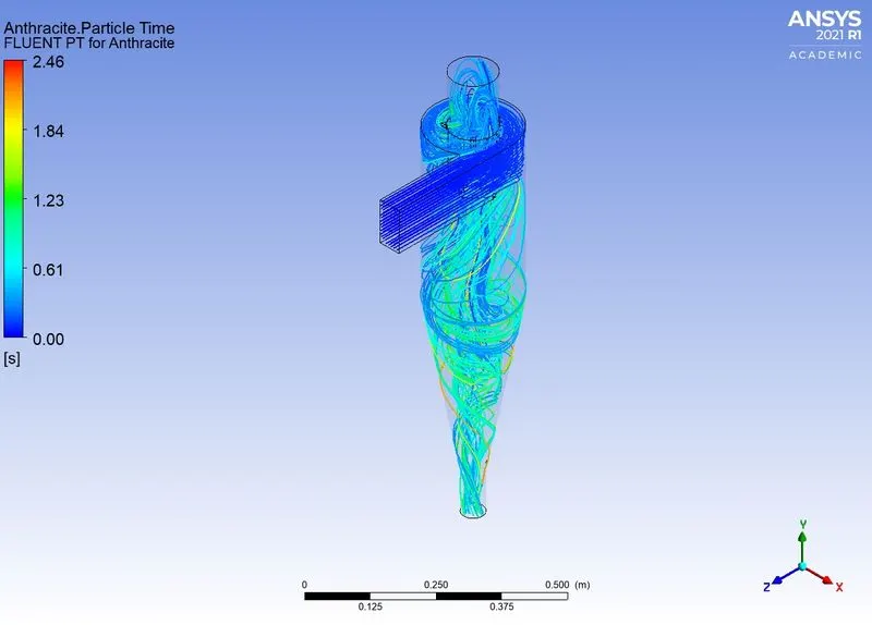 |
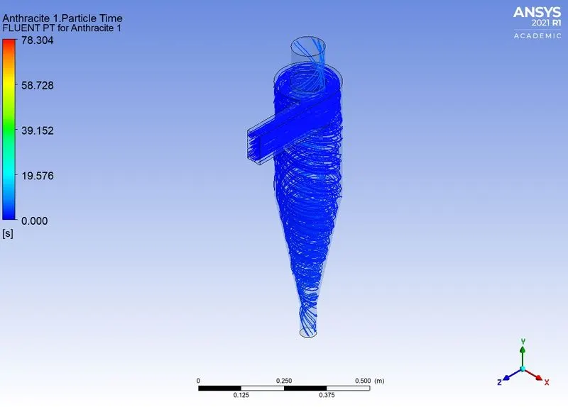
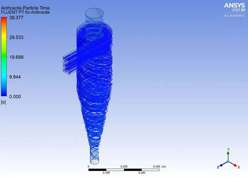
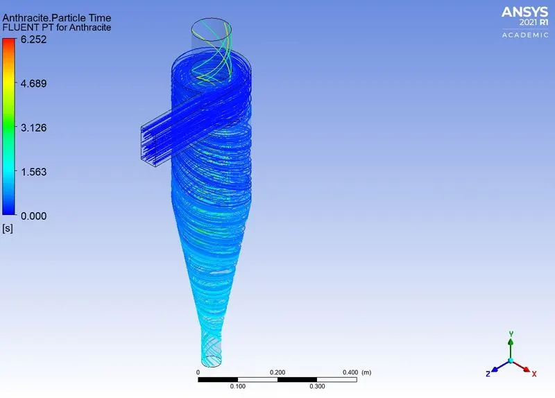
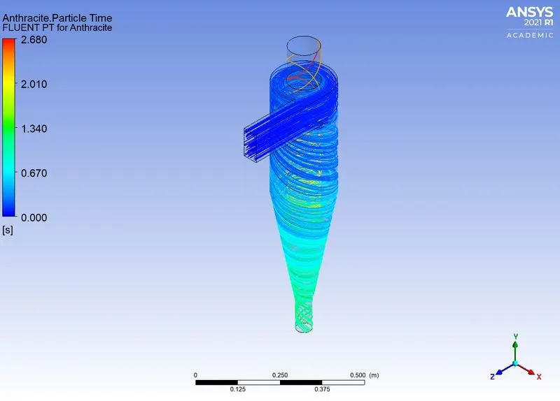
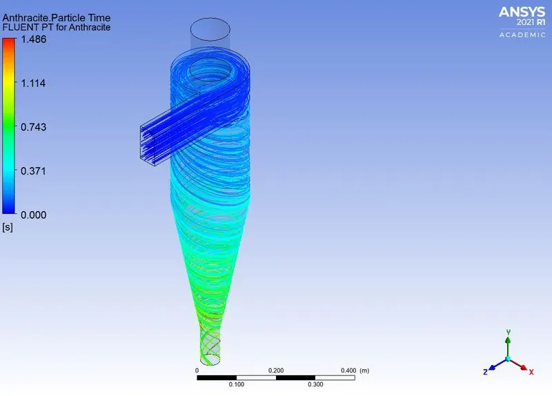
Case 2: Varying the velocity for constant size of the particle:
| Velocities | Velocity | Particle time |
| 1 m/s | 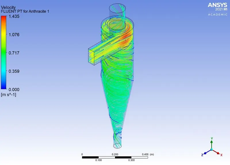 |
 |
| 2 m/s | 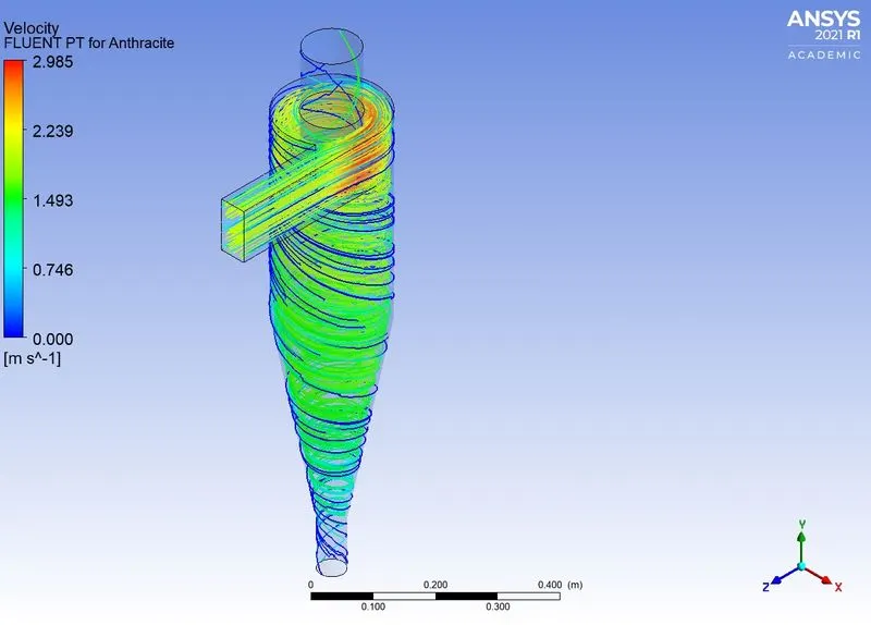 |
 |
| 3 m/s | 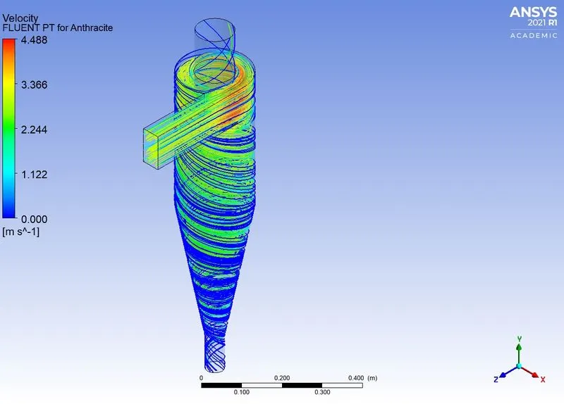 |
 |
| 4 m/s | 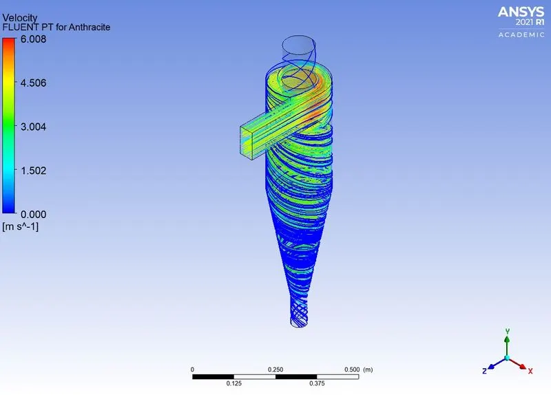 |
 |
| 5 m/s | 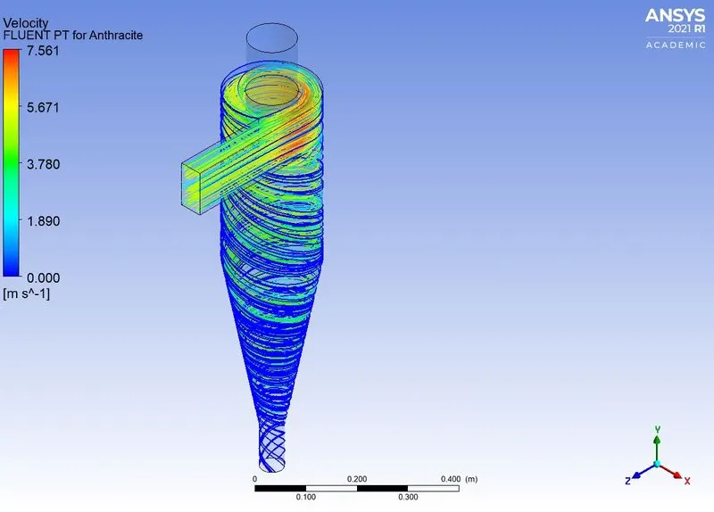 |
 |
Discussion on the efiiciency of different cases:
Case 1: For varying size (velocity = 3m/s)
| Size | Tracked | Escaped | Trapped | Incomplete | Efficiency |
| 1e-6 | 91 | 12 | 40 | 39 | 43.95% |
| 2e-6 | 91 | 4 | 61 | 26 | 67.03% |
| 3e-6 | 91 | - | 89 | 2 | 97.8% |
| 4e-6 | 91 | 32 | 22 | 37 | 24.17% |
| 5e-6 | 91 | 13 | 72 | 6 | 79.12% |
Case 2: For varying Velocity (Size: 5e-6)
| Velocity | Trackeed | Escaped | Trapped | Incomplete | Efficiency |
| 1 m/s | 408 | 39 | 29 | 340 | 1.36% |
| 2 m/s | 408 | 21 | 16 | 371 | 6.51% |
| 3 m/s | 408 | 33 | 284 | 91 | 14.97% |
| 4 m/s | 408 | 13 | 395 | - | 27.27% |
| 5 m/s | 408 | 1 | 407 | - | 43.71% |
In conclusion, the study conducted to understand the effects of varying size of the particles to varying the velocity of the flow sows the result and the efficiency attained by the separator under given boundary conditions.
The efficiency for the lower velocity is arbitaray as at times the particles are not escaping, this results to recirculation inside the body of the separator. This is clearly not the case in higher velocities as the efficiency is higher with no incomplete particles.