Week 8 - Simulating Cyclone separator with Discrete Phase Modelling
AIM: To perform analysis on Cyclone Separator and calculate the separation efficiency and pressure drop.
OBJECTIVE:
- To write a few words about any four empirical models used to calculate separator efficiency.
- To perform an analysis on a given cyclone separator model by varying the particle diameter from `1mum` to `5mum` and calculate the separation efficiency in each case. Discuss the results. [Use both the velocities as 3m/sec].
- To perform an analysis on a given cyclone separator model by varying the particle velocity from 1 m/sec to 5 m/sec and calculate the separation efficiency and pressure drop in each case. Discuss the results. [Use particle diameter size as `5mum` for all cases and keep flow velocity same as particle velocity].
THEORY:
Cyclone Separator:
The first thing to realize is the Cyclone separator has several colloquial names, these names include Dust Separator, Dust Collector, Dust Extractor, Cyclone Extractor. Generally smaller units are referred to as Dust Separator or Extractors whilst large-scale industrial Separators are referred to as Cyclone Separators. For this reason, we will be using the term Cyclone Separator throughout the project.
Let's talk about the basics of Cyclone separator, There are two main designs of Cyclone separator, Gas cyclone, and Hydro cyclone. Gas cyclones are used to remove entrained particles from a gas stream. Hydro cyclones are used for separating fluids of different densities.
Cyclone separators can be installed as single units or in multiple known as multi cyclones. Separators can be installed with horizontal or vertical orientation. It is also possible to install cyclones in series or in parallel.
Gas Cyclone Separator
Gas cyclone separators are grouped into two main categories, Reverse flow and Axial flow. Reverse flow cyclone separators are cone-shaped, gas enters at the top of the separator body, flows downwards then flows back upwards, and is discharged. For Axial flow cyclone separators, gas enters at one end and is discharged at the opposite end. The axial flow design is not as common as the reverse flow design.
The project will focus on the reverse flow gas cyclone separator because this type of separator is the most commonly used today.
Components and Design
A Reverse flow cyclone separator is an industrial assembly with no moving parts and a simple design. The main cylindrical part of the cyclone separator is known as the body or barrel, the gradually narrowing conical section is known as the cone. Untreated gas enters tangentially through the inlet at the side of the separator. Entrained particles within the gas stream are separated from the gas stream and discharged through the reject port of the base of the separator. Clean gas exits through the accept port at the top of the separator.
Working of the Cyclone Separator
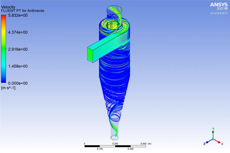
Gas containing entrained particles enters at high velocity through the tangential inlet at the top of the cyclone. The gas flows into the cyclone body at a tangent and begins to flow in a circular downward flowing spiral towards the lower reject port. This downward flowing spiral is referred to as a spiral vortex. The cone diameter gradually decreases which causes the gas velocity to increase the outer vortex creates an additional inner vortex closer to the center of the separator body and this inner vortex flows spirally upwards toward the accept port.
Particles with more inertia will impact the side of the cyclone, whilst particles with lower inertia will remain within the gas stream. Inertia can be thought of as a particle's ability to continue traveling in a straight line, even when external forces are applied.
When an external force is applied such as by the cyclonic vortex, particles with low inertia will not continue to travel in a straight line. They will instead travel sparely as they are swept along by the gas stream. Particles with great inertia will be less affected by the vortex and will continue traveling in a straight line. This straight-line trajectory causes the high inertia particles to move out of the gas stream and impacts the cyclone separator body. These particles then fall to the base of the cyclone separator and out of the reject port.
In this way, entrained particles of a certain size can be separated from the gas stream.
Another way to think of this process is to think of higher-density particles colliding with the cyclone body whilst less dense particles are retained within the gas stream. This is not strictly true though as both the density and the shape of the particle will affect its ability to be separated from the gas stream. Particles discharged through the reject port are usually either recycled back into the process or disposed off.
Factors affecting the Efficiency:
There are several factors that can affect the cyclone separator efficiency. These include particle density, particle size, volumetric flow rate, pressure drop, cone length, body length, the ratio of accepting port to body diameter, and even the smoothness of the cyclone's internal surfaces.
We will now discuss the most important design aspects:
Particle Density
Particle density is one of the most deciding factors, affecting the cyclone's ability to remove entrained particles. Dense particles such as various oxides can be separated with a 99% or greater efficiency, irrespective of particle size. Dense particles are easily separated. When the particle density decreases, the efficiency decreases.
Particle Size
Particle size is a large design consideration affecting the separator's efficiency. Larger particles can be more easily separated than smaller particles. Particles smaller than five microns are difficult to separate without using very small separators. Particles exceeding 200 microns can often be separated using other means, such as gravity settling chambers. A reduction in particles size will give a corresponding reduction in efficiency.
Geometry
A separator's geometry greatly impacts the efficiency of the unit. A large diameter cyclone separator will not be able to separate particles as efficiently as a smaller diameter separator. The efficiency of the separator increases as the cone diameter decreases. Thus reducing the cone diameter, enables the removal of finer and finer particles. A small diameter cone will extract much finer particles from a gas stream than the larger diameter cone.
Pressure Drop
All cyclone separators have an associated pressure drop. The pressure drop can be thought of as the amount of energy required to move the gas through the separator. Alternatively, it can be thought of as the amount of resistance the cyclone separator adds to the system flow.
Separator body to accept port diameter ratio
Finally, another way to increase a separator's efficiency is to reduce accept port diameter. This changes to separator body to accept port diameter ratio and has the effect of only allowing finer particles to leave the separator through the accept port.
Large or Small separator
Small cyclone separators have a higher efficiency rating but the associated pressure drop is high and the volumetric flow rate is low. Gas velocity through a small separator is also very high and this will lead to a higher level of erosion if the gas stream contains abrasive particles.
Large cyclone separators have a lower efficiency rating but the associated pressure drop is low and the volumetric flow rate high. A large cyclone separator is not suitable for removing fine particles from a gas stream.
Advantages and Disadvantages:
There are many advantages associated with cyclone separators some of these include cheap to purchase, low maintenance, suitable for high temperatures, suitable for liquid mist and vapors, do not requiring much space.
Some disadvantages are associated with cyclone separators but these disadvantages can be reduced in severity if the correct separator is selected for the correct application. Disadvantages may include high operating costs, associated with the pressure drop across the separator, inefficient when handling smaller fine particles, and not being suitable for sticky substances.
CYCLONE EFFICIENCY EMPIRICAL MODELS:
Iozia and Leith Model:
Iozia and Leith's (1990) logistic model is a modified version of Barth's (1956) model which is developed based on force balance. The model assumes that a particle carried by the vortex endures the influence of two forces: a centrifugal force, Z, and flow resistance, W. Core length, `z_c`, and core diameter, `d_c`, is given as
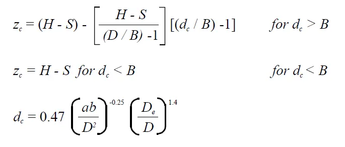
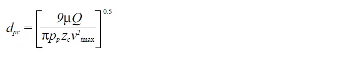
The addition made by Iozia and Leith on the original Barth (1956) model is the core length `z_c` and slope parameter `beta` expression which is derived based on the statistical analysis of experimental data of cyclone with D = 0.25 m. The collection efficiency `eta_i` of particle diameter `d_(p i)` can be calculated from

where `d_(p c)` is the 50% cut size by Barth (1956)
Li and Wang Model:
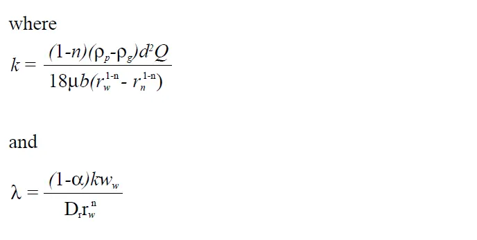
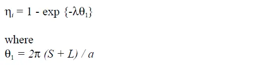
The Li and Wang (1989) model include particle bounce or re-entrainment and turbulent diffusion at the cyclone wall. A two-dimensional analytical expression of particle distribution in the cyclone is obtained. Li and Wang's model was developed based on the following assumptions:
- The radial particle velocity and the radial concentration profile are not constant, for uncollected particles within the cyclones.
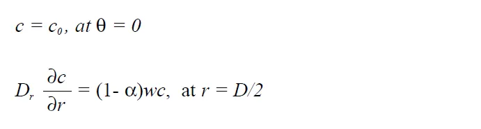
- Boundary conditions with the consideration of turbulent diffusion coefficient and particle bounce re-entrainment on the cyclone wall are:
- The tangential velocity is related to the radius of the cyclone by: `uR^n`= constant.
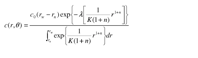
The concentration distribution in a cyclone is given as:
The resultant expression of the collection efficiency for particles of my size is given as
Koch and Licht Model:
Koch and Licht's (1977) collection theory recognized the inherently turbulent nature of cyclones and the distribution of gas residence times within the cyclone. Koch and Licht describe particle motion in the entry and collection regions with the additional following assumptions:
- The tangential velocity of a particle is equal to the tangential velocity of the gas, i.e. there is no slip in the tangential direction between the particle and the gas.
- The tangential velocity is related to the radius of the cyclone by: `uR^n`= constant.
A force balance and an equation on the particles collection yields the grade efficiency `eta_i`.
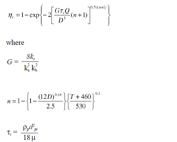
G is a factor related to the configuration of the cyclone, n is related to the vortex and `tau` is the relaxation term.
Lapple Model:
Lapple's (1951) model was developed based on force balance without consideration the flow resistance. Lapple assumed that a particle entering the cyclone is evenly distributed across the inlet opening. The particle that travels from the inlet half-width to the wall in the cyclone is collected with 50% efficiency. The semi-empirical relationship developed by Lapple (1951) to calculate a 50% cut diameter, `d_(pc)`, is
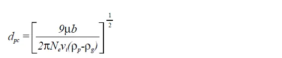
where `N_e` is the number of revolutions

The efficiency of collection of any size of the particle is given by

SOLUTION:
In this project, we will perform an analysis of a given Cyclone model in two different manners:
- By varying particle diameters.
- By varying particle velocities.
To carry out this analysis, we will be using what is called DPM which stands for Discrete Phase Modeling. Discrete Phase Modeling is employed when you want to represent solid particles in the gas or liquid or say liquid droplets in a gas or sometimes bubble in the liquid. In DPM they will consider two phases one is called the continuous phase and the other is called the discrete phase. The continuous phase will consist of the fluid that is flowing within the fluid volume and the discrete phase will consist of the smaller particles that are supposed to be interacting with the continuous phase. The discrete phase can also exchange momentum, mass, and energy with the fluid phase or the continuous phase in this case.
Steps followed for Simulation:
Geometry Preparation:
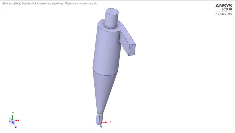
- Imported the geometry in the SpaceClaim.
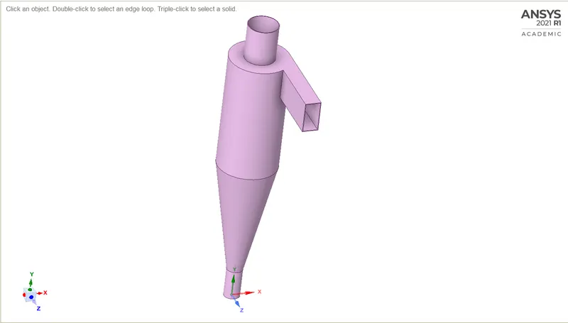
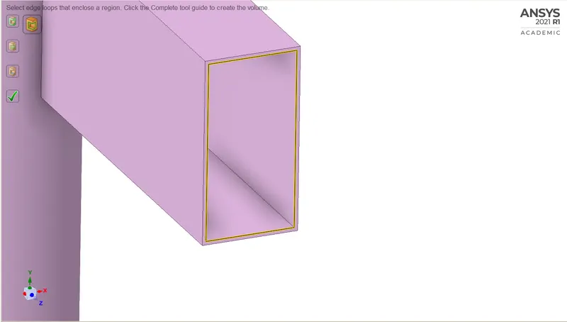
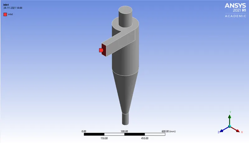
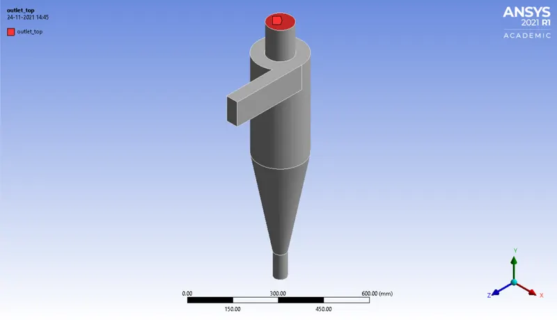
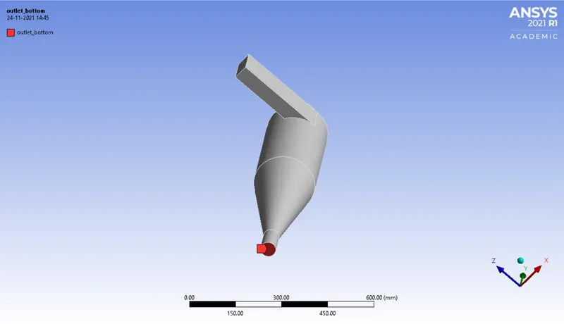
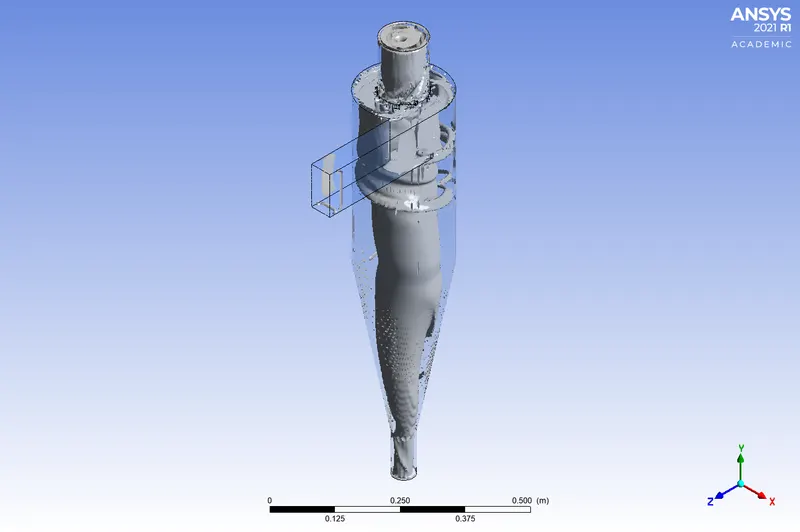
- We need to carry out the analysis on the fluid volume so in order to do that we have to extract the fluid volume within the cyclone separator. With the help of the volume extraction tool, selected edge to select all the inlets and outlets to extract the fluid volume. In a cyclone separator, we have two outlets so one of the outlets is for the lighter air and towards the bottom, we have an outlet for the heavier particles. Selected all of them and then clicked to complete.
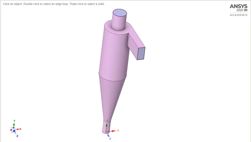
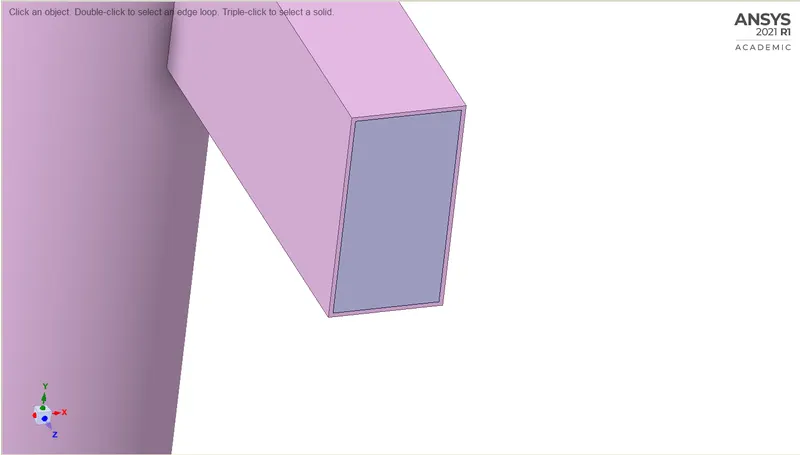
- Fluid volume has been extracted so we can Hide and suppress the cyclone separator geometry, so the cyclone separator geometry would not pop into the analysis part.
Meshing:
Named Selections
Setup:
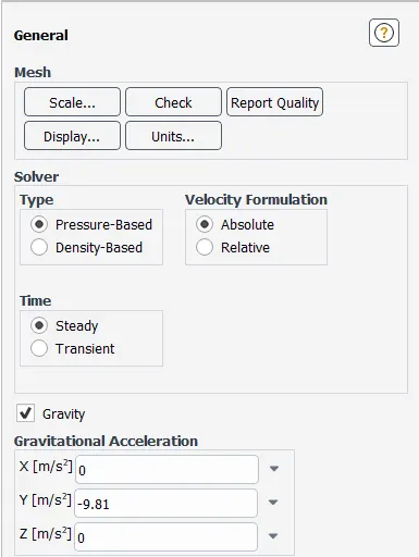
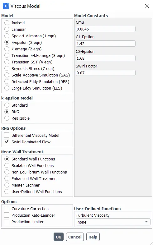
- RNG K-epsilon model is a slight modification of the standard k-epsilon model, which enhances the accuracy of swirling flows, so for our particular case, this would be much more accurate.
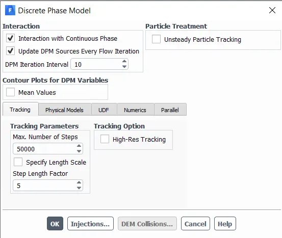
- There are two ways of carrying out the discrete phase modeling one is uncoupled flow and the second is the coupled flow. In the uncoupled flow, the discrete phase will not have any interaction with the continuous phase whilst in the coupled flow the discrete phase will influence the flow of the continuous phase. Since the size of the particles injected into the cyclone separator is very small so the use of both types of flow should not matter much. So here we have selected "interaction with continuous phase" to enable the coupled flow.
- Now we have the option of updating the DPM sources every flow iteration. while enabling this option gives you the chance to calculate the particle source terms at every iteration. For an unsteady simulation, this is recommended and it is given by default.
- DPM iteration interval, this option allows you to control the frequency at which the particle is attracted. If you specify the higher interval, it will be computationally less heavy but it would not make much difference.
- In the tracking parameter, the Maximum number of steps is the timesteps that we specify and it is the number of time steps that are used to compute a single particle trajectory. In case the fluent exceeds these number of steps, it will automatically cancel the reporting of the trajectory. Consider a case where certain particles are trapped within the recirculation region, so by specifying the maximum number of steps we can stop fluent from tracking that particular particle infinitely. For steady-state 50000is the maximum number of steps that is given by default.
- Now we have two options below the maximum number of steps that is Specify Length Scale and Step Length Factor. Both these options are used to control the time step size. If you take the Specify Length Scale option the time step will be calculated by dividing the length scale by the velocity of the discrete particle and with the velocity of the continuous phase. Ideally, we would go for a lesser value of the length scale so a smaller value for the length scale increases the accuracy of the trajectory b providing a smaller value for the time step size. The same goes for the Step Length Factor as well. It also controls the time steps, while calculating the time step using a step length factor the larger, the larger the step length factor the smaller the time step will be. Here we go for default settings.
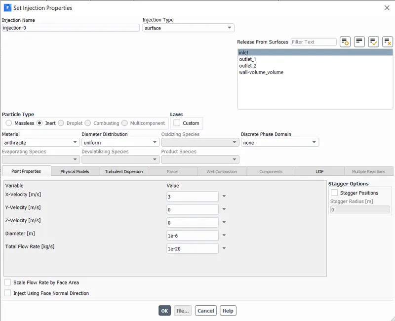
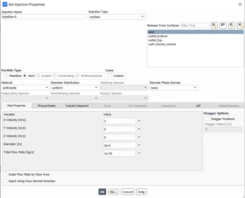
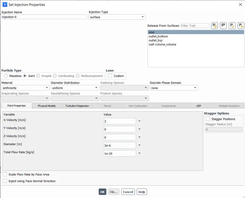
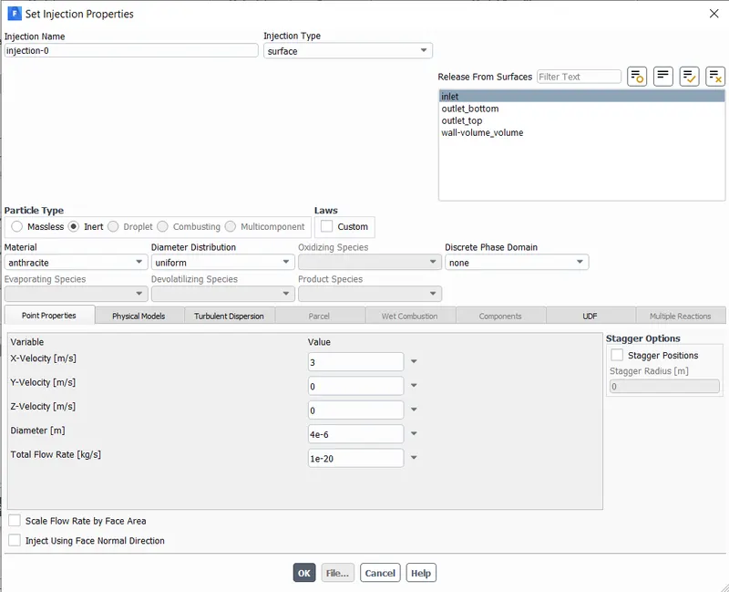
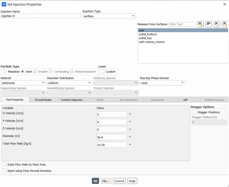
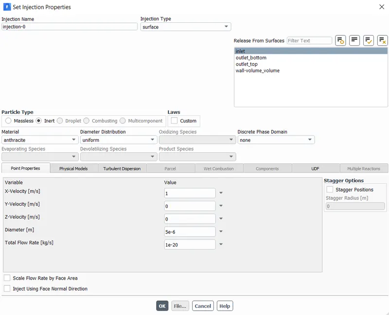
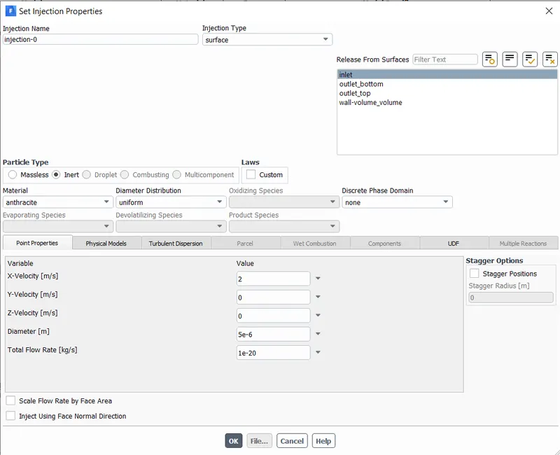
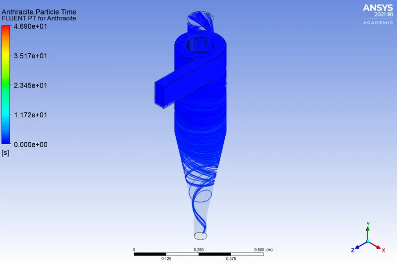
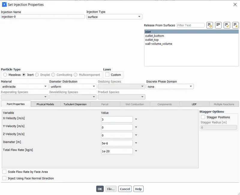
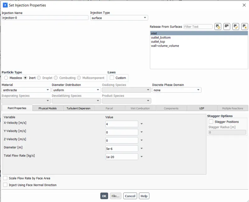
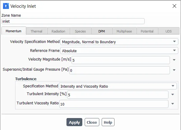
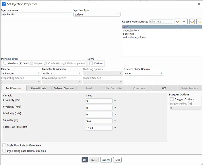
- Now we have to specify the injection of the discrete particles on the continuous phase. Particle type will be inert, and we will be injecting Anthracite, Anthracite is the type of coal and this should be relevant to our particular simulation. Set the injection type as a surface injection, and select the inlet that we defined so the velocity that we specify here will act normally to the surface that is the inlet.
- We have given the value of velocity as 3m/s in the X direction and the diameter is `1mum` for part 1 of case 1.
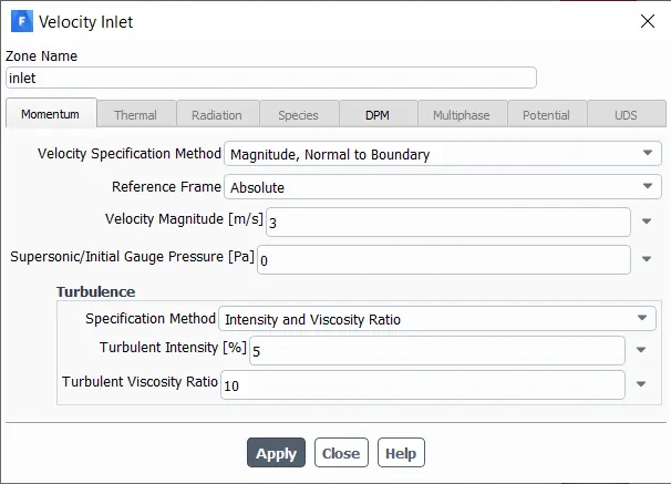
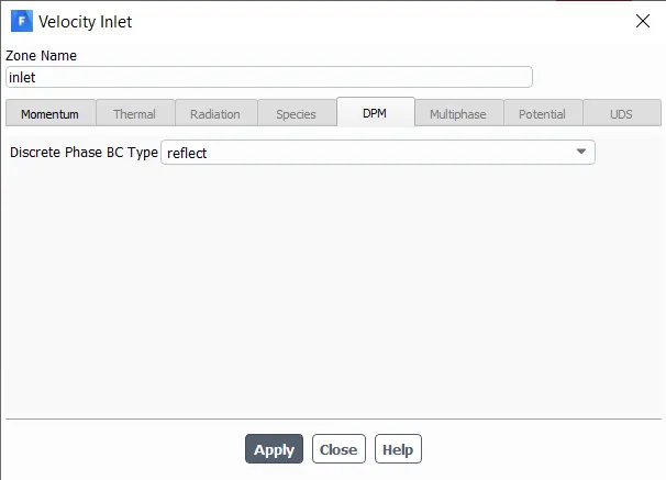
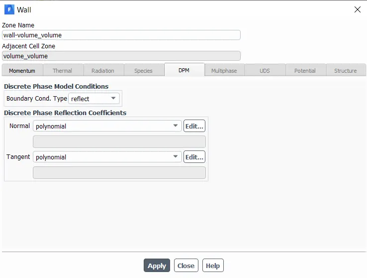
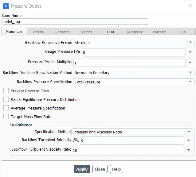
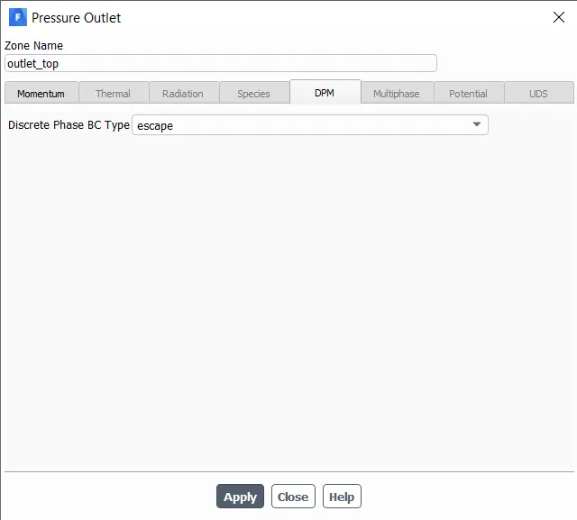
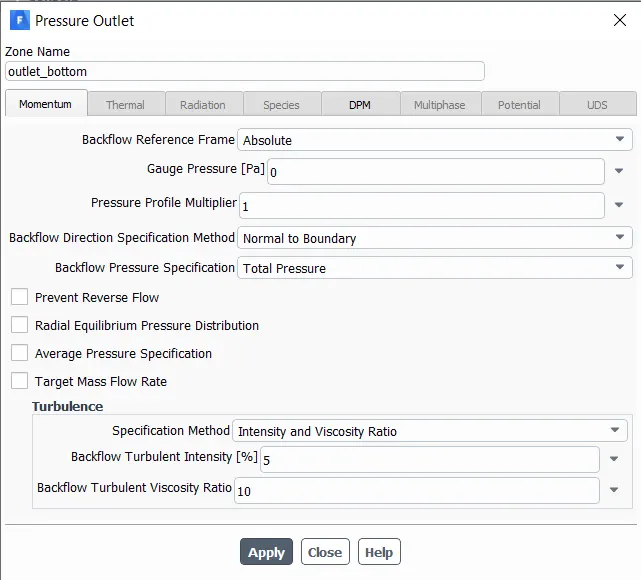
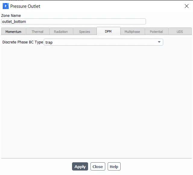
- Now we need to specify the boundary conditions.
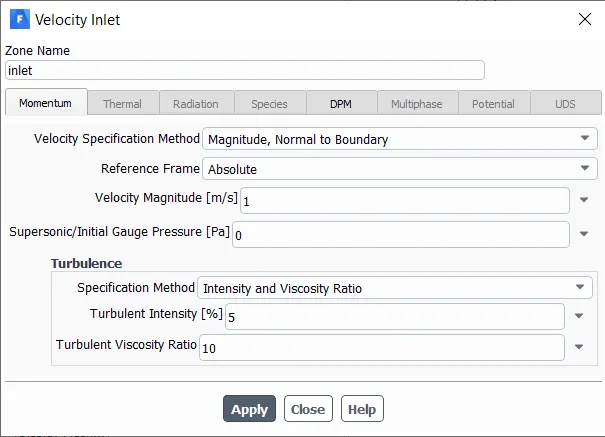
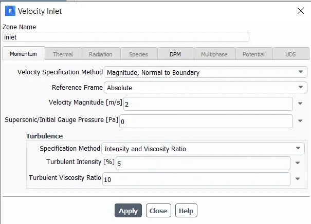
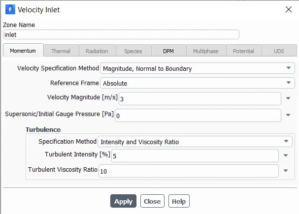
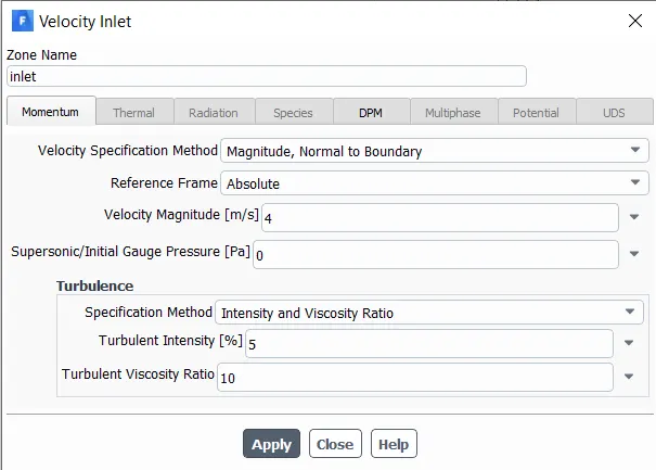
- A velocity magnitude of 3m/s is given.
- Discrete Phase BC Type is set as reflect
Solution method
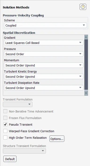
- Selected Second-Order Upwind for the Turbulent Kinetic Energy and Turbulent Dissipation Rate. Second-order upwind is a more accurate special discretization scheme for this type of problem.
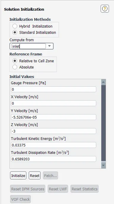
- Since this particular problem has inlets and outlets, we can go for Standard Initialization.
Results
CASE 1: By varying particle diameters
(A). For Particle Diameter `1mum` (velocity 3m/s)
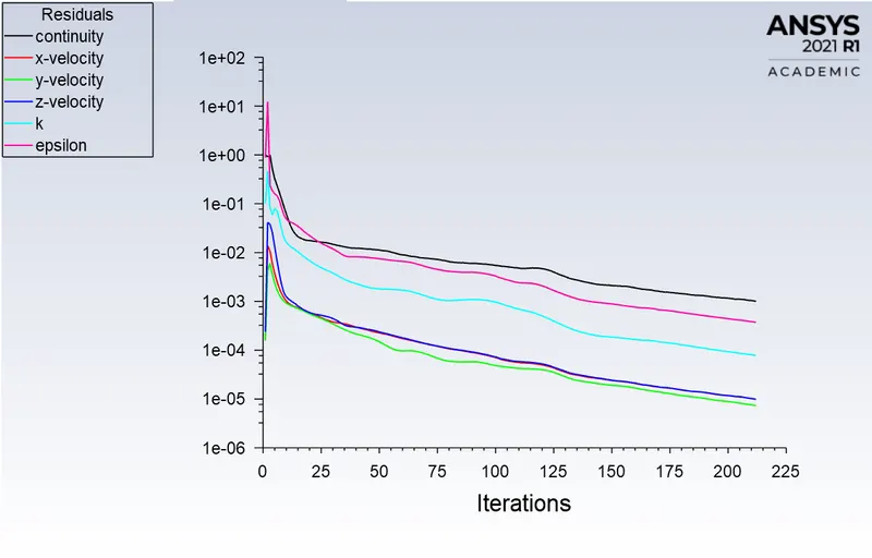
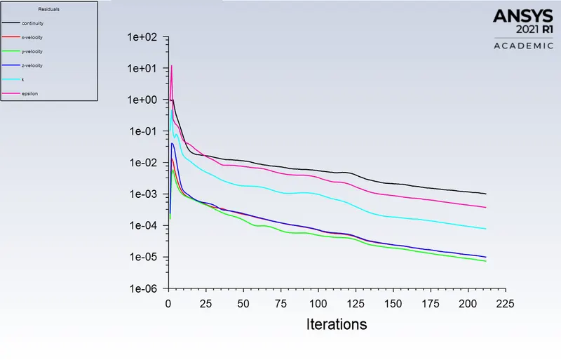
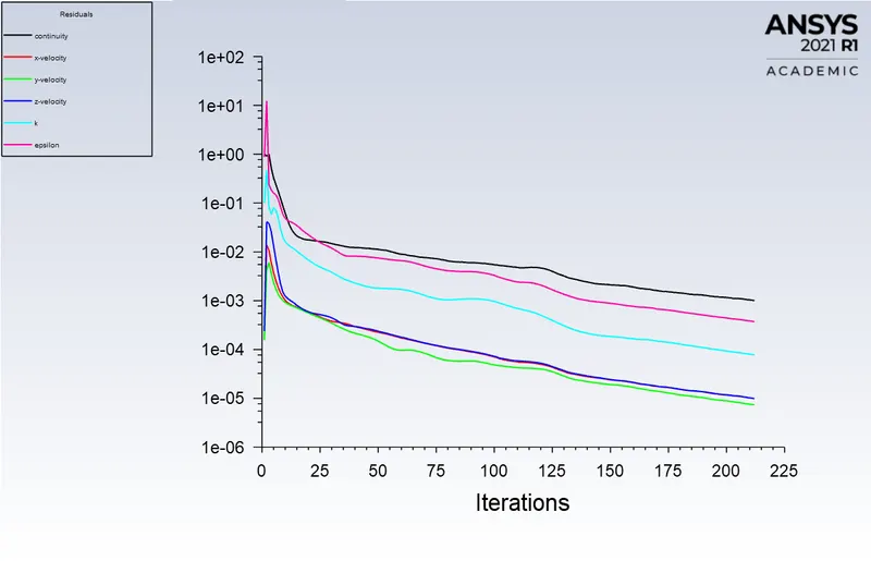
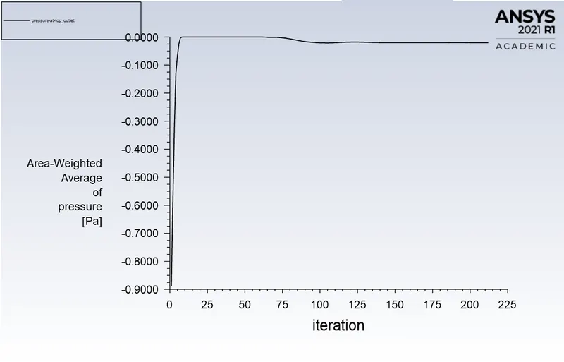
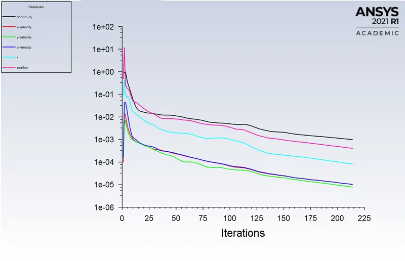
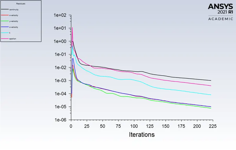
Residuals

Escaped: Escape BC reports the particle as having “escaped”.
Trapped: Trap boundary condition enables to terminate the trajectory calculation of a particular particle and thus to record the respective particle as trapped.
Incomplete: Incomplete particles are those particles whose trajectory calculations were terminated when the maximum allowed time steps defined in the DPM properties were exceeded.
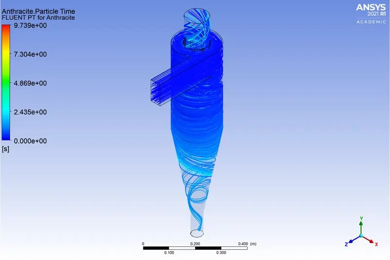
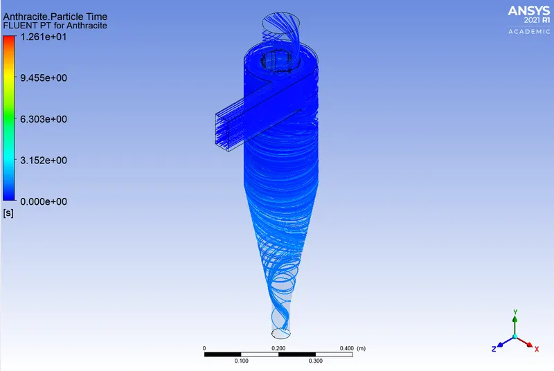
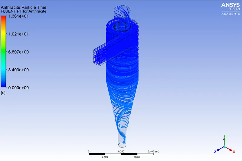
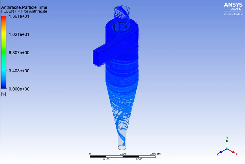
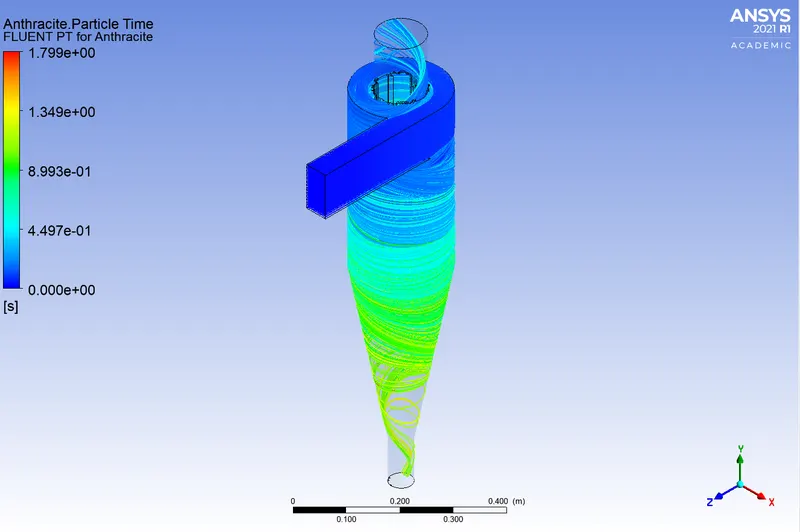
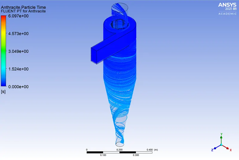
Anthracite Particle Time
(B). For Particle Diameter `2mum` (velocity 3m/s)
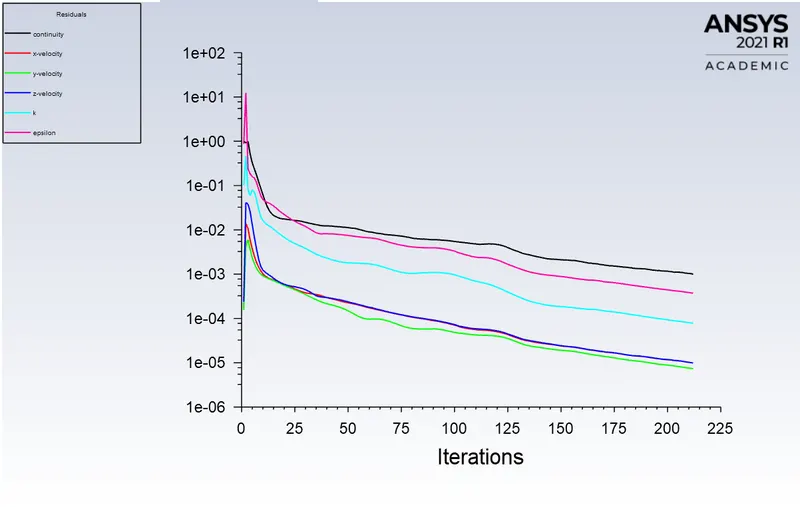
Residuals

Anthracite Particle Time
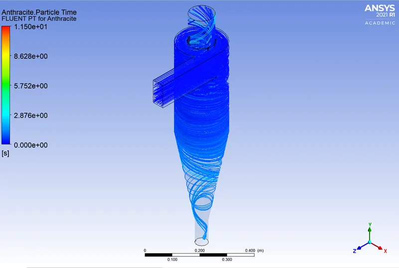
(C). For Particle Diameter `3mum` (velocity 3m/s)
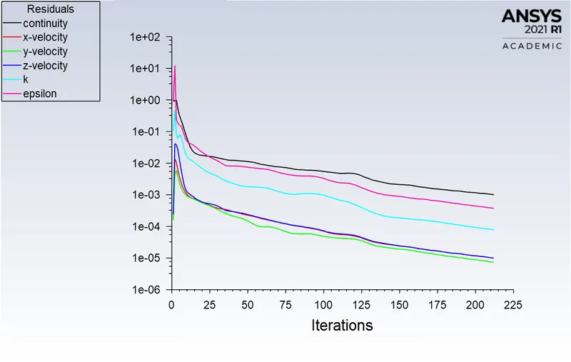
Residuals

Anthracite Particle Time
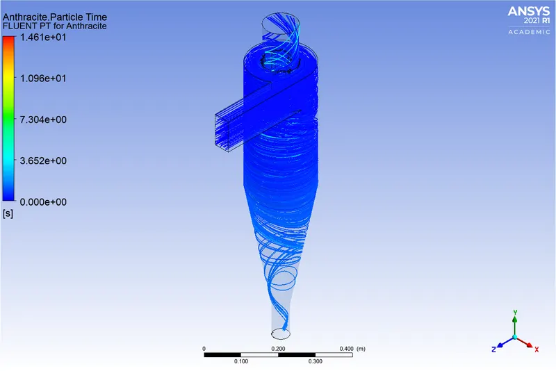
(D). For Particle Diameter `4mum` (velocity 3m/s)
Residuals

Anthracite Particle Time
(E). For Particle Diameter `5mum` (velocity 3m/s)
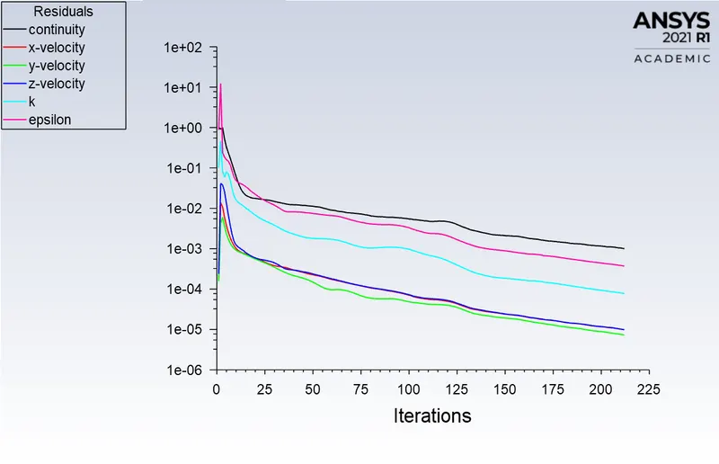
Residuals

Anthracite Particle Time
Separation Efficiency = (Number of particles trapped / Number of particles tracked) * 100
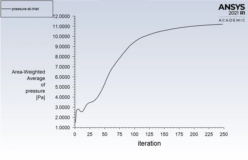
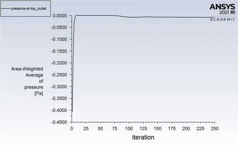
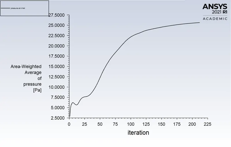
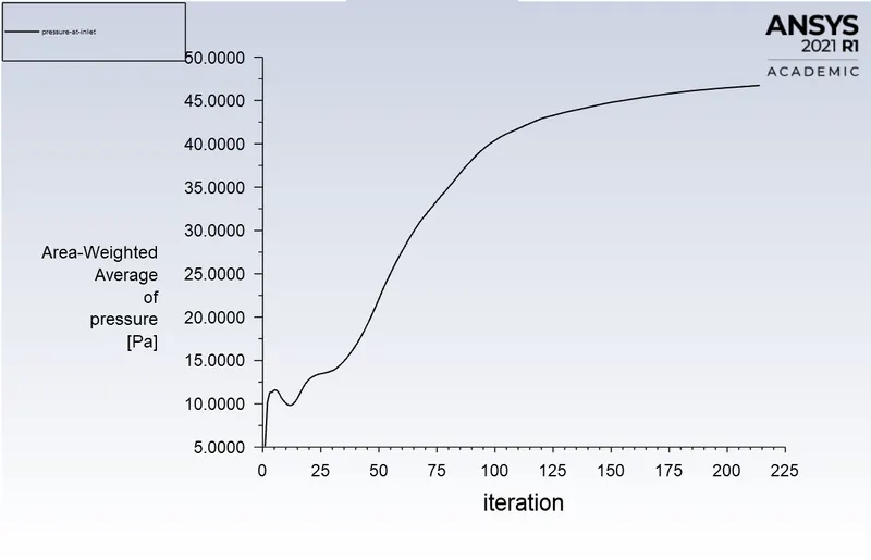
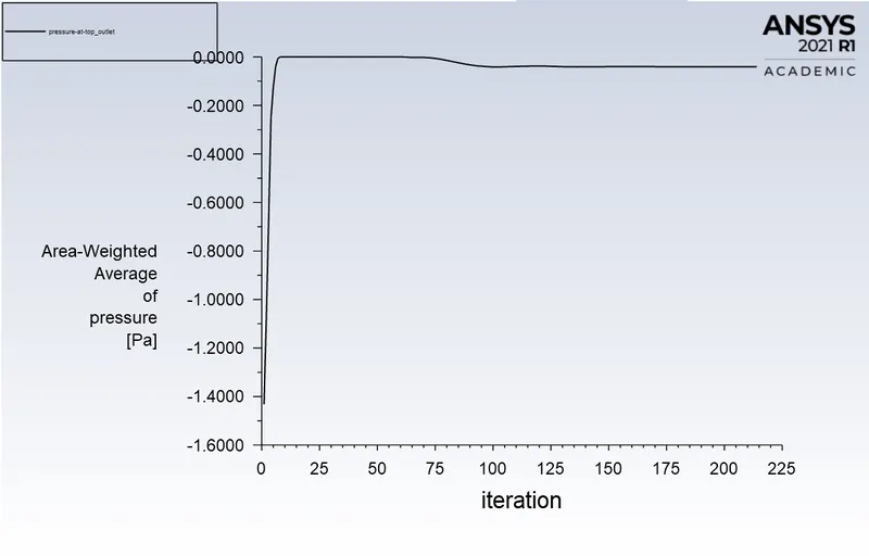
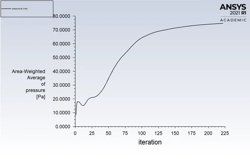
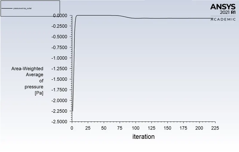
Pressure Drop = Pressure at the inlet - Pressure at outlet
Observations from the above Simulations:
| Particle Diameter in (`mum`) with Velocity 3m/s | The number of Particle Tracked | The number of Particle Escaped | The number of Particle Trapped | The number of Particle Incomplete | Separation Efficiency in (%) | Pressure Drop in (Pa) |
| 1 | 378 | 155 | 132 | 91 | 34.92 | 25.6166 |
| 2 | 378 | 125 | 144 | 109 | 38.09 | 25.6166 |
| 3 | 378 | 103 | 149 | 126 | 39.41 | 25.6166 |
| 4 | 378 | 76 | 203 | 99 | 53.70 | 25.6166 |
| 5 | 378 | 72 | 256 | 50 | 67.72 | 25.6166 |
- From the above simulations, it is noted that the increase in the particle size resulted in a decrease in escaped particles and an increase in trapped particles.
- As the particle diameter increases, the separation efficiency also increases.
- Thus the Particle size is a large design consideration affecting the separation efficiency.
- We can say that the larger particles can be more easily separated than the smaller particles.
CASE 2: By varying particle velocities
(A). For Particle Velocity 1m/s (Diameter `5mum`)
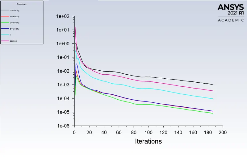

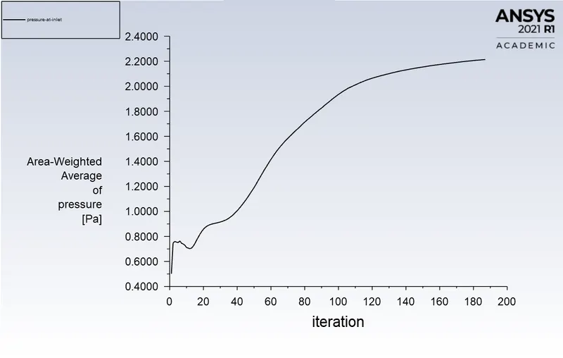

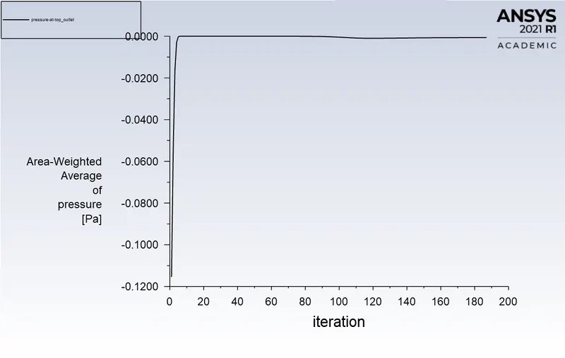

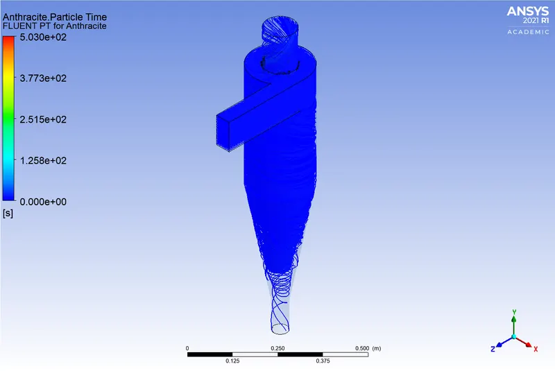
(B). For Particle Velocity 2m/s (Diameter `5mum`)



(C). For Particle Velocity 3m/s (Diameter `5mum`)



(D). For Particle Velocity 4m/s (Diameter `5mum`)



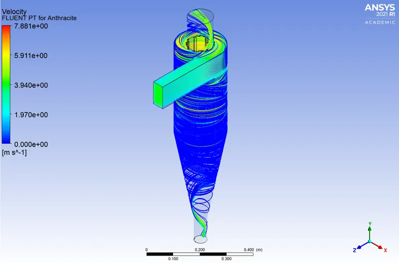
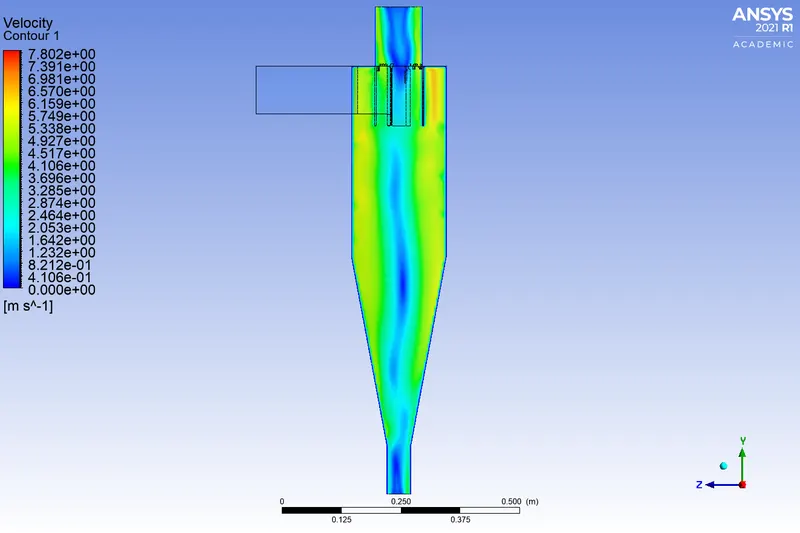
(E). For Particle Velocity 5m/s (Diameter `5mum`)



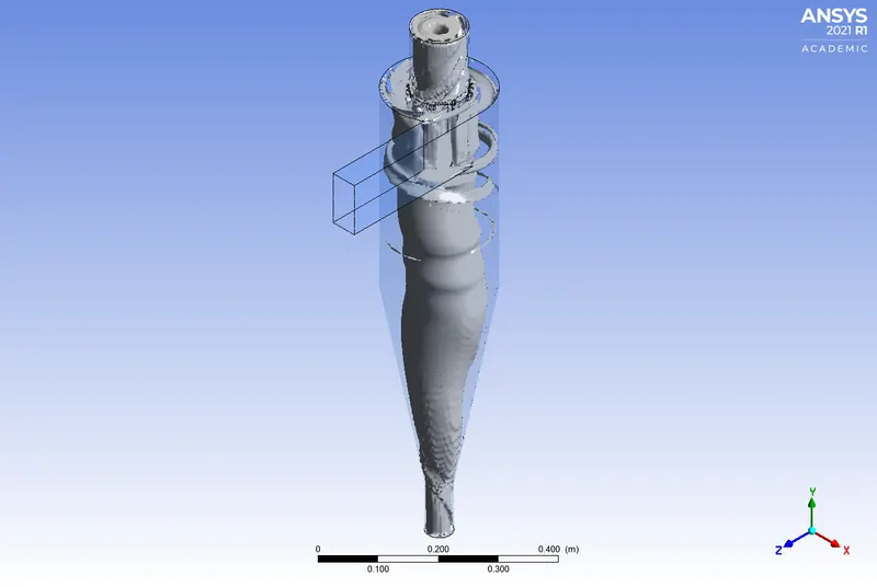
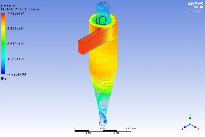
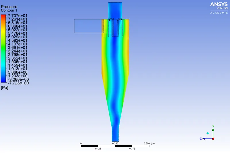
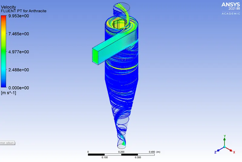
Observations from the above Simulations:
| Particle Velocity in (m/s) with Diameter `5mum` | The number of Particle Tracked | The number of Particle Escaped | The number of Particle Trapped | The number of Particle Incomplete | Separation Efficiency in (%) | Pressure Drop in (Pa) |
| 1 | 378 | 104 | 3 | 271 | 0.79 | 2.21326 |
| 2 | 378 | 74 | 41 | 263 | 10.84 | 11.18974 |
| 3 | 378 | 72 | 256 | 50 | 67.72 | 25.61659 |
| 4 | 378 | 65 | 313 | 0 | 82.80 | 46.69621 |
| 5 | 378 | 70 | 298 | 10 | 78.83 | 74.60378 |
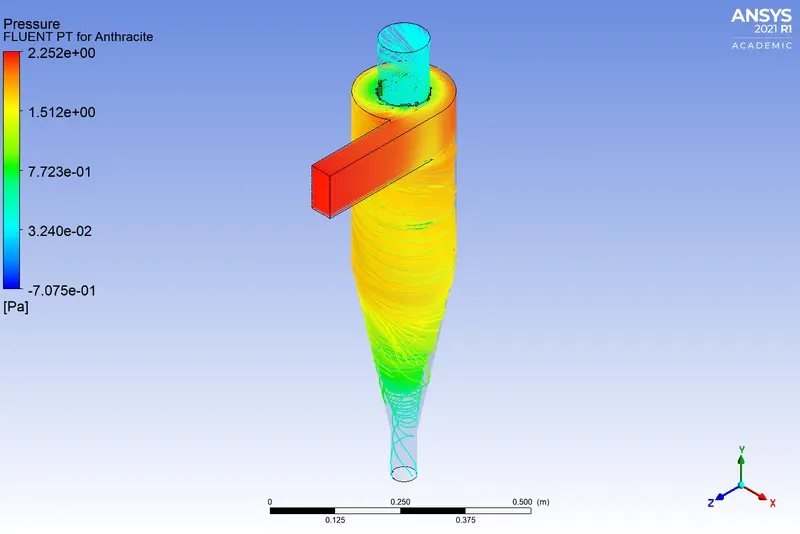
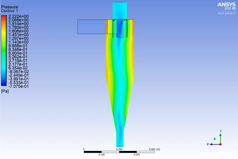
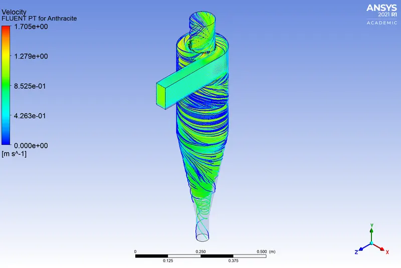
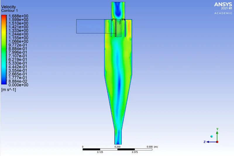
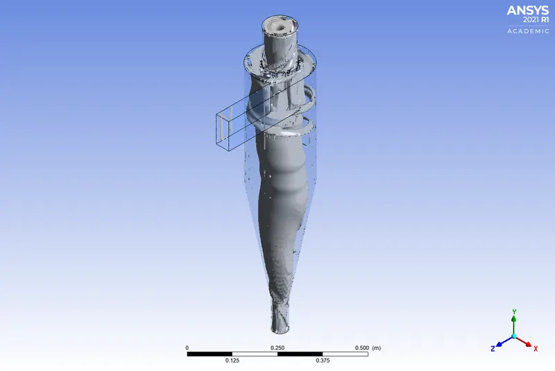
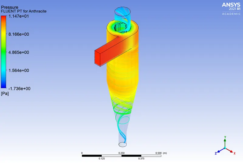
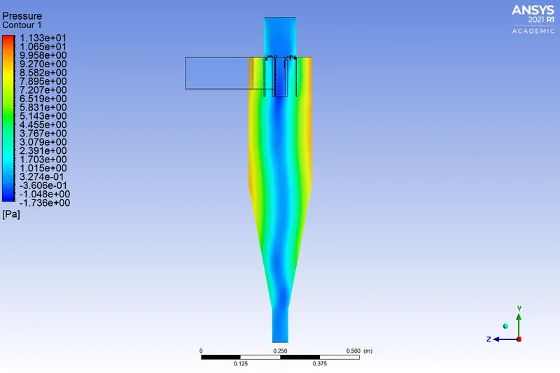
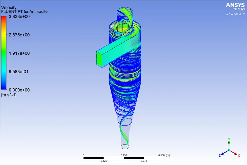
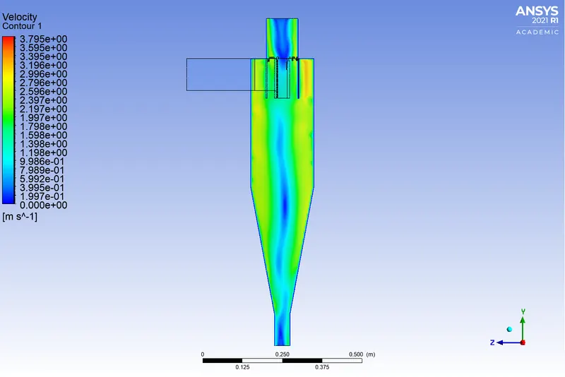
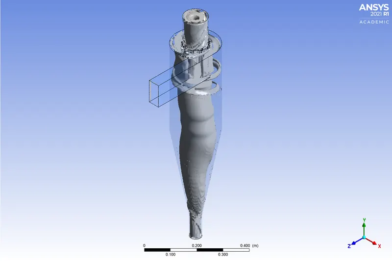
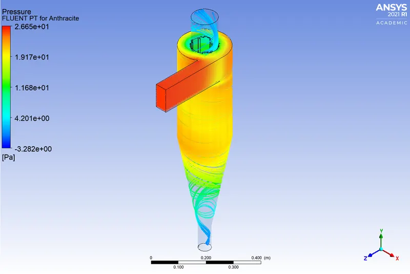
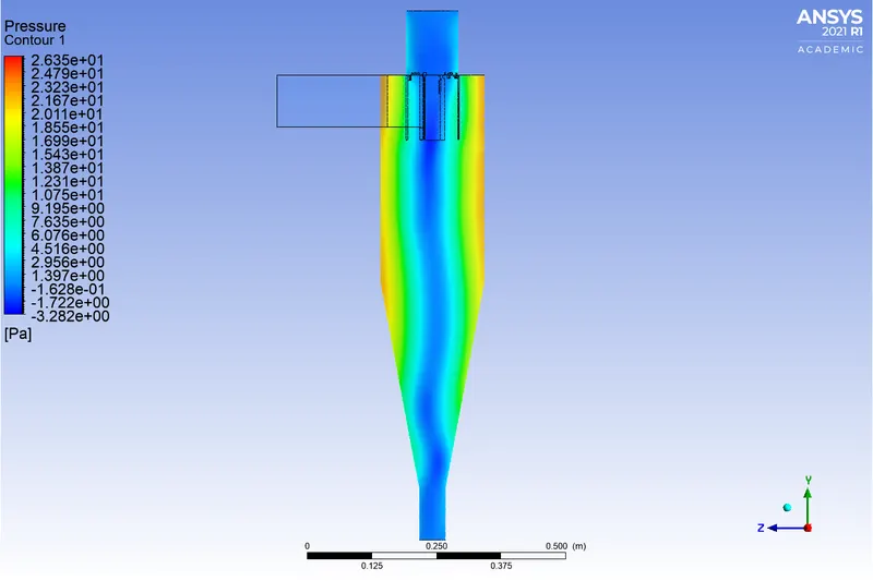
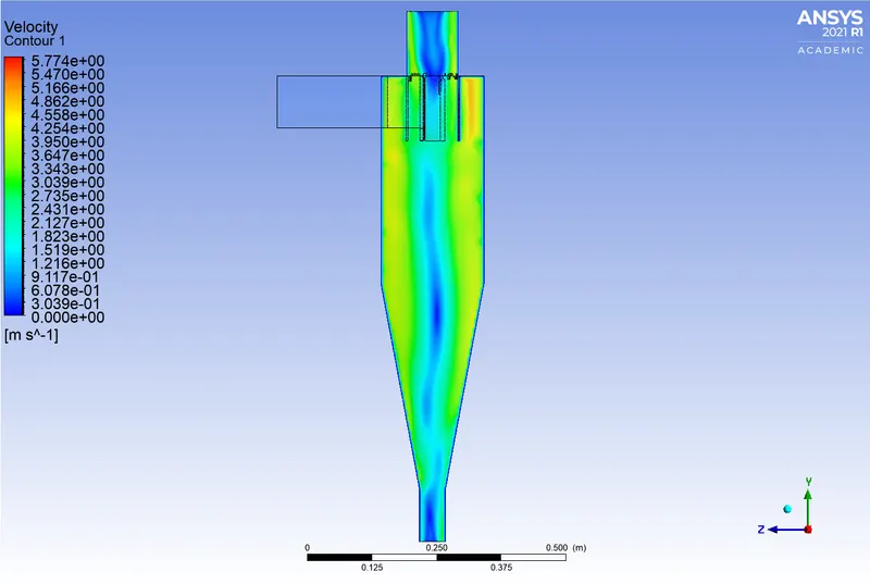
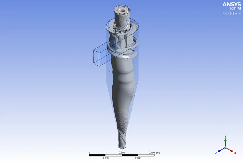
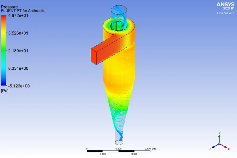
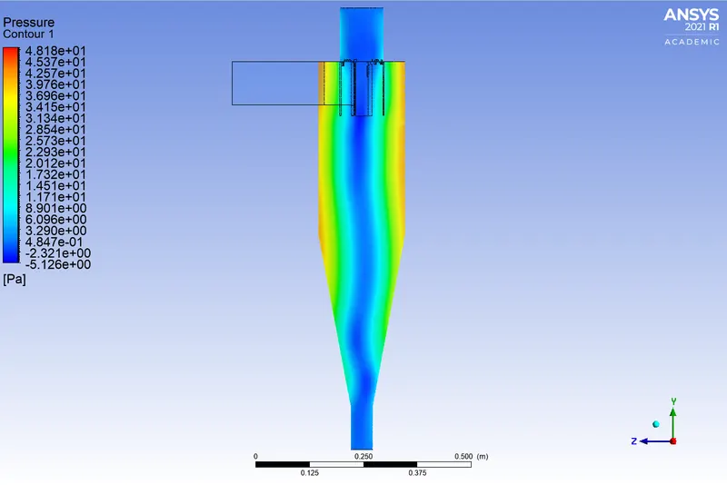
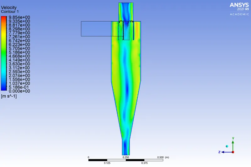
- From the pressure contour, we can see that the pressure is low at the center of the cyclone separator and higher near the wall which forms the outer vortex, This outer vortex creates an additional inner vortex closer to the center of the separator body and this inner vortex flows spirally upwards towards the top outlet i.e. the accept port. Then the lighter particles tend to escape from the top outlet and heavier particles are collected at the bottom outlet.
- From the above table, we can observe that as the velocity increases the number of particles trapped increases, and thus the separation efficiency increases.
- From the above table, it can also observe that the separation efficiency of a cyclone separator has a direct effect on the pressure drop. As the efficiency increases the pressure drop increases.
CONCLUSIONS:
- There are several factors that can affect the cyclone separator efficiency, from the project we saw the two factors that are the diameter of the particles and the velocity of the particles on which the cyclone separator efficiency depends.
- Particle size and separation efficiency are directly proportional.
- Higher velocity is more effective for higher efficiency.
- The higher efficiency of the cyclone separator has a higher pressure drop.