Week 8 - Simulating Cyclone separator with Discrete Phase Modelling
Aim:- To perform analysis on cyclone separator and calculate the separation efficiency and pressure drop.
Objective:-
- To write a few words about any four empirical models used to calculate the cyclone separator efficiency.
- To perform an analysis on a given cyclone separator model by varying the particle diameter from 1 μm to 5 μm and calculate the separation efficiency in each case. Discuss the results. [Use both the velocity's as 3m/sec.]
- To perform an analysis on a given cyclone separator model by varying the particle velocity from 1 m/sec to 5 m/sec and calculate the separation efficiency and pressure drop in each case. Discuss the results. [Use particle diameter size as 5 μm for all cases & keep flow velocity same as particle velocity]
Introduction
Chemical processes consist of reaction stages and/or separation stages in which the process streams are separated and purified. Such separations involve physical principles based on differences in the properties of the constituents in the stream. Heterogeneous mixtures consist of two or more phases which have different composition. These mixtures consist of components that do not react chemically and have clearly visible boundaries of separation between the different phases. Components of such mixture can be separated using one or more appropriate techniques. These separation processes includes Gas-Liquid (vapor-liquid) separation, Gas-Solid separation (vapor-solid), Liquid-Liquid separation (immiscible), Liquid-Solid, and Solid-Solid separation etc. This separation can be done by exploiting the differences in density between the phases. Gravitational force or centrifugal force can be used to enhance the separation. The separation units can be either horizontal or vertical. The main techniques used to separate the phases, and the components within the phases, are discussed in details. The principle methods for the separation of such mixtures could be classified as:
Cyclone separator, Gas-Liquid separator, Liquid-Liquid separator, Gravity separator, Centrifugal separator, High speed tubular centrifuge Scrubbers , Electrostatic precipitator, Hydro cyclone
CYCOLNE SEPARATOR
Cyclone separators provide a method of removing particulate matter from air or other gas streams at low cost and low maintenance. Cyclones are somewhat more complicated in design than simple gravity settling systems, and their removal efficiency is much better than that of settling chamber. Cyclones are basically centrifugal separators, consists of an upper cylindrical part referred to as the barrel and a lower conical part referred to as cone . They simply transform the inertia force of gas particle flows to a centrifugal force by means of a vortex generated in the cyclone body. The particle laden air stream enters tangentially at the top of the barrel and travels downward into the cone forming an outer vortex. The increasing air velocity in the outer vortex results in a centrifugal force on the particles separating them from the air stream. When the air reaches the bottom of the cone, it begins to flow radially inwards and out the top as clean air/gas while the particulates fall into the dust collection chamber attached to the bottom of the cyclone.
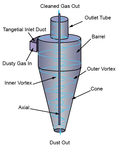
Emperical models to calculate the efficienncy of a cyclone seperator
- Lozia and Leith Model:- Iozia and Leith logistic model is a modified version of Barth Model, which is developed based on force balance. The model assumes that a particle carried by the vortex endures 165 the influence of two forces: a centrifugal force, Z and a flow resistance, W. The collection efficiency `eta_i` of particle diameter dpi can be calculated from the equation given below
`eta_i = 1/(d_(pc)/d_(p i))^beta`
`beta` is an expression for slope parameter derived based on the statistical analysis of experimental data of a cyclone with D = 0.25 m given as
`beta = 0.62-0.87ln(d_(pc)/100)+5.21ln((ab)/D^2)+1.05(ln((ab)/D^2))^2`
dpc is the 50% cut size given by Barth
`d_(pc) = [(9muQ)/(pirhoZ_cV_(tmax)^2]]^0.5`
where core length Zc and core diametre dc are given as
`Z_c = (H-S)-((H-S)/((D/B)-1))((d_c/B)-1)` for dc > B
`Z_c =H-S for dc < B`
`d_c = 0.47D((ab)/D^2)^-0.25(D_e/D)^1.4``
`d_(p i)` - Diametre of particle in size range i (m)
i - subscript denotes interval n partcicle size
`beta` - Slope parametre
a - Cyclone inlet height
b - Cyclone inlet width
`mu` - Viscosity
Q - Discharge
`Z_c` = Core length
`V_(tmax)` - Maximum tangential velocity
H - cyclone length
S - Cyclone gas outlet duct length
D - Cyclone body diametre
B - Cyclone dust outlet diametre
De - Cyclone gas outlet diametre
- Li and Wang Model :- The Li and Wang model includes particle bounce or re-entrainment and turbulent diffusion at the cyclone wall. A two-dimensional analytical expression of particle distribution in the cyclone is obtained. Li and Wang model was developed based on the following assumptions:
• The radial particle velocity and the radial concentration profile are not constant for uncollected particles within the cyclone.
• Boundary conditions with the consideration of turbulent diffusion coefficient and particle bounce re-entrainment on the cyclone wall are:
C = Co at `theta = 0`
`Dr (delc)/(delr) = (1-alpha)omegaC` at r = D/2
• The tangential velocity is related to the radius of cy-clone by: `uR^n` = constant.
`C(r,theta) = C_o(r_w-r_n)exp{-lambda(1/(k(1+n))r^(1+n)})/(int_(rn)^(rw)exp{1/(k(1+n)r^(1+n))}dr`
`k = ((1-n)(rho_p-rho_g)d^2Q)/(18mub(r_w^(1-n)-r_n^(1-n))`
`lambda = ((1-alpha)komega_w)/(D_rr^nw`
the resultant expression of the collection efficiency for particle of any size is given as
`eta_i = 1-exp{-lambdatheta_1}`
`theta_1 = 2pi(S+L)/a`
C1,C0 - Particle inlet, outlet Concentration
Dr- Radial turbulent diffusion coefficient
K - Cyclone configuration and operating condition constant
n - cyclone vortex exponent
`rho_p,rho_g` - Denotes the mass densities of particle and gas respectively
`alpha`- Particle bounce or re-entartainment coefficient
`lambda` - Charactarisitice value
`omega` - radial particle valocity
`theta` - Angular co-ordinate
L - natural length
- Lapple model :- it was developed based on force balance with-out considering the flow resistance. Lapple assumed that a particle entering the cyclone is evenly distributed across the inlet opening. The particle that travels from inlet half width to the wall in the cyclone is collected with 50% efficiency. The semi empirical relationship developed by Lapple to calculate a 50% cut diameter, dpc, is
`d_(pc) = [(9mub)/(2piN_ev_i(rho_p-rho_g)]]`
Where Ne is the number of revolutions
`N_e = 1/a[h+(H-h)/2]`
The efficiency of any size of particle is give by
`eta_i = 1/(1+(d_(pc)/d_(p i))^2`
`v_i` - Inlet velocity
h - Cyclone cylinder height
- Koch and Licht Model :- Koch and Licht collection theory recognized the inherently turbulent nature of cyclones and the distribution of gas residence times within the cyclone. Koch and Licht described particle motion in the entry and collection regions with the additional following assumptions:
• The tangential velocity of a particle is equal to the tangential velocity of the gas flow, i.e. there is no slip in the tangential direction between the particle and the gas.
• The tangential velocity is related to the radius of cyclone by `uR^n` = constant.
A force balance and an equation on the particles collection yields the grade efficiency `eta_i`
`eta_i -= 1-exp{-2[(Gtau_iQ)/D^3(n+1)]^(0.5/(n+1)}}`
Where G = `(8K_c)/(K_a^2K_b^2`
n = 1- `{1-(12D)^0.14/2.5}{(T+460)/530}^0.3`
`tau_i = (rho_pd_(p i)^2)/(18mu)`
`G` - Cyclone configuration factor
`tau_i` - Relaxation time
`K_c` - Cyclone volume constant
`K_b` - b/D
Ka - a/D
G is a factor related to the configuration of the cyclone, n is related to the vortex and `tau` is the relaxation term`
Methodology
- Since the case for this simulation involves discrete phase modelling it will have two phases of following types
- Continues phase in which it refers to fluid flowing through the fluid volume
- Discrete phase are the particles that are supposed to be interacting with the continues phase
Geometry
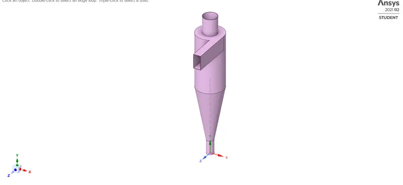
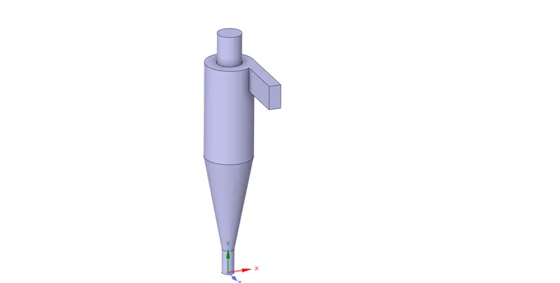
- The geometry was loaded onto spaceclaim
- Fluid volume is extracted using edges option
- The cyclone seperator geometry is suppressed
Mesh
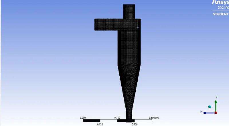
- Named selection is added as inlet, outlet 1(upper outlet) and outlet 2 (lower outlet)
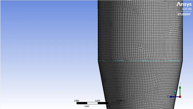
- A mesh size of 4e-3 m is given
- The mesh type is set to hexagonals of quad only
Setup
- Steady state analysis is selected with the presence of gravity of 9.81 m/s
- The viscous model is set to K-epsilon of RNG model (RNG model is selected for swirl accuracy) and swirl dominated flow is also selected
- Discrete phase model is turned on
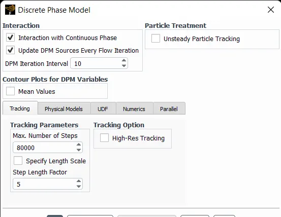
- There is actually two types of DPM flows and they are coupled and uncoupled flow.The coupled flow activates the interaction of discrete phase on continues phase while the uncoupled flow will not have any interactions
- I have turned on the interaction of discrete phase with the continues phase
- Also update DPM sourece every flow iteration is enabled and DPM interval is set to 10
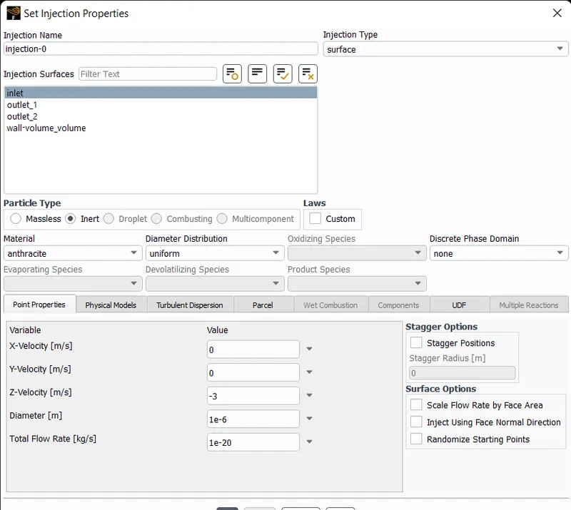
- Then Injection is selected to set the particle diametre and inlet velocity of particles
- For the first case I will be changing only the particle sizes while the velocity is set to 3 m/s(particle sizes from 1e-6 m to 5e-6 m)
- For the boundary conditions the inlet velocity is set to 3 m/s for the first case and for the second case the particle size is set to 5 e-6 m and the velocity is changed from 1 to 5 m/s as seperated cases
- The inlet DPM is set to reflect
- The upper outlet (outlet 1) DPM is set to escape and the bottom outlet (outlet 2) is set to trap
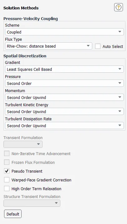
- The solution method is set to Coupled which is more effective in this case ( I previously did this calculation using SIMPLE and it had too many incomplete particles)
- The calculation initialised with standard one and compute from inlet is selected
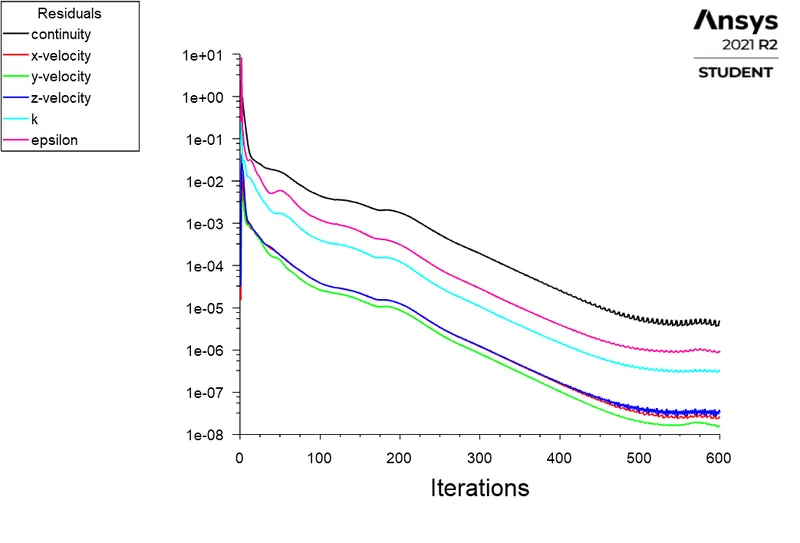
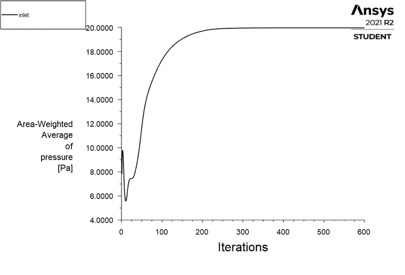
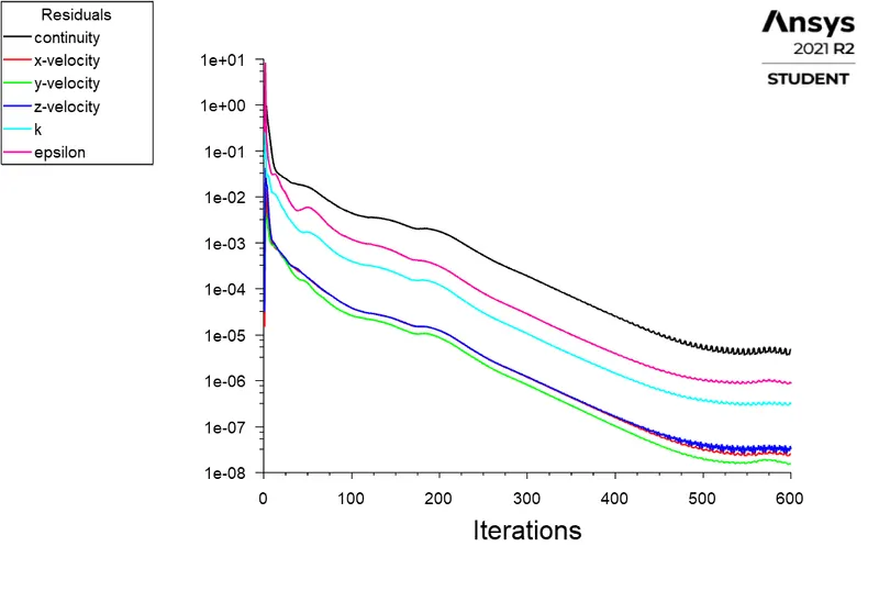
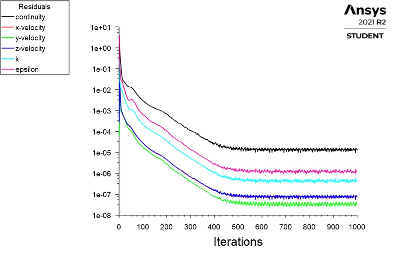
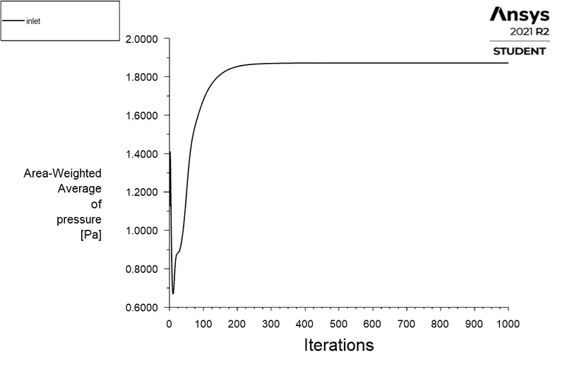
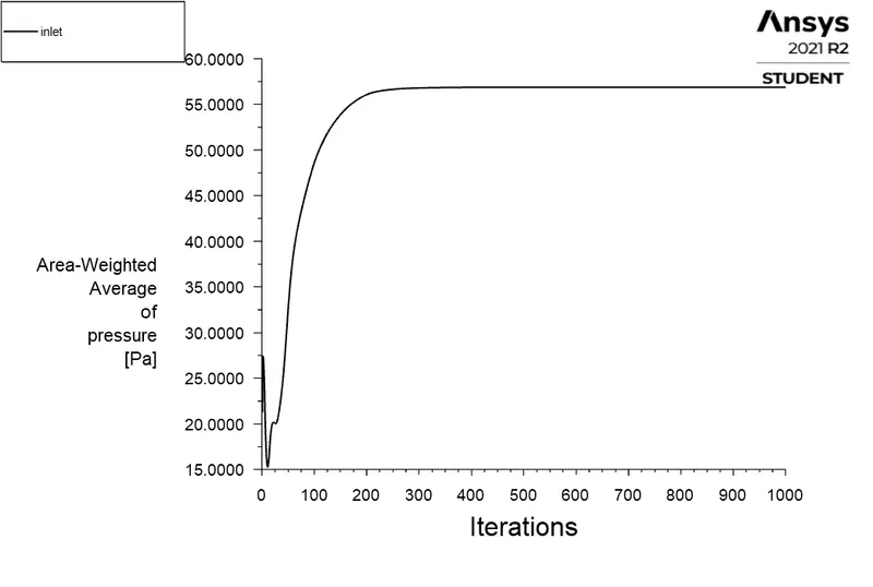
- Number of Iterations is set to 600 as the solution converges around 550 iterations (I did second case first which was done with 1000 iterations)
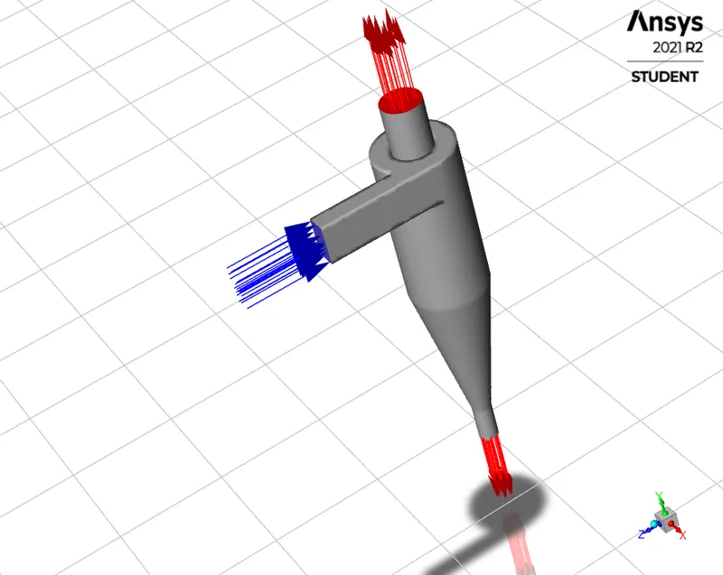
Outputs
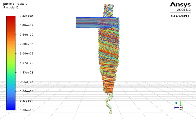
Case 1 - Particle size 1 micro metres
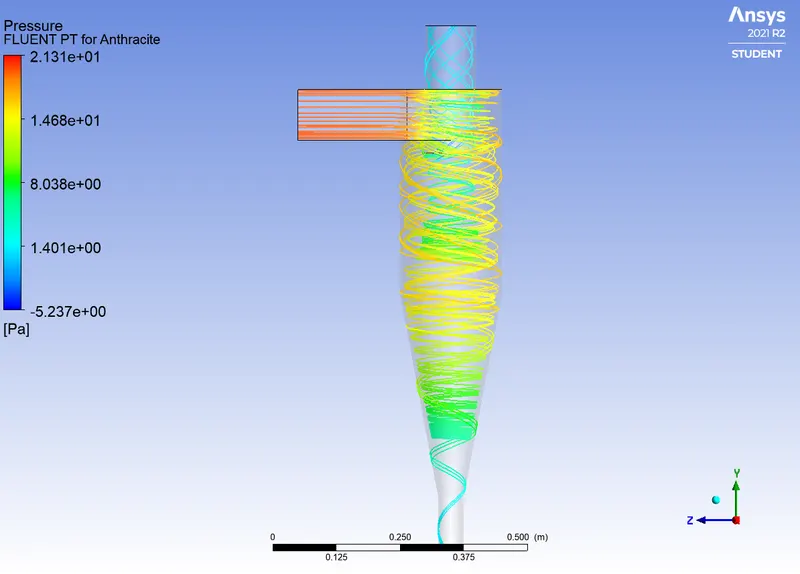
Number of particles tracked = 334
Number of particles escaped = 121
Number of particles trapped = 178
Number of incomplete particles = 35
Seperation efficiency = (178/334)*100 = 53.293 %
Case 1 - Particle size 2 micro metres
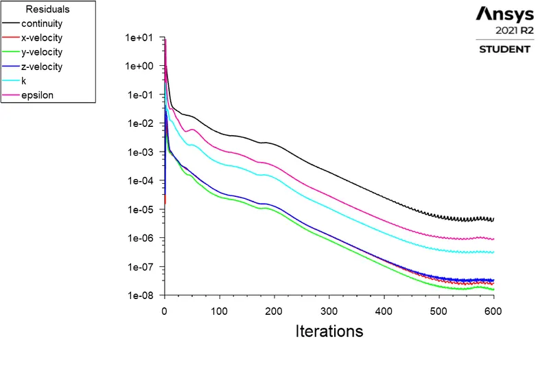
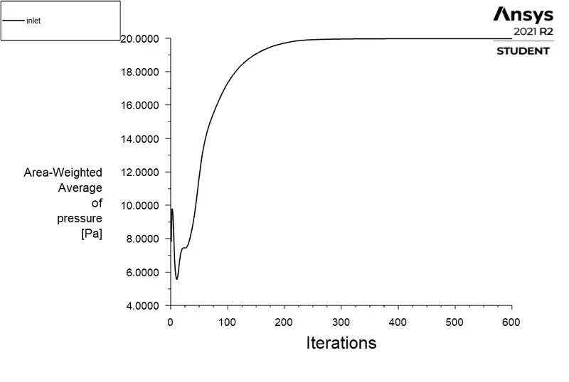
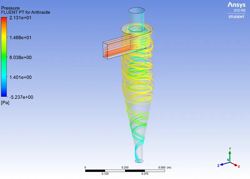
Number of particles tracked = 334
Number of particles escaped = 99
Number of particles trapped = 201
Number of incomplete particles = 34
Seperation efficiency = (201/334)*100 = 60.18 %
Case 1 - Particle size 3 micro metres
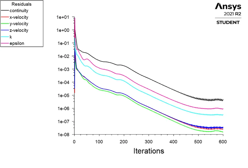
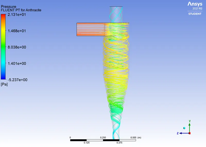
Number of particles tracked = 334
Number of particles escaped = 67
Number of particles trapped = 239
Number of incomplete particles = 28
Seperation efficiency = (239/334)*100 = 71.556 %
Case 1 - Particle size 4 micro metres
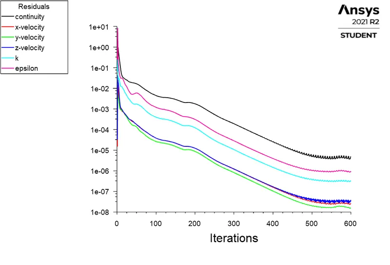
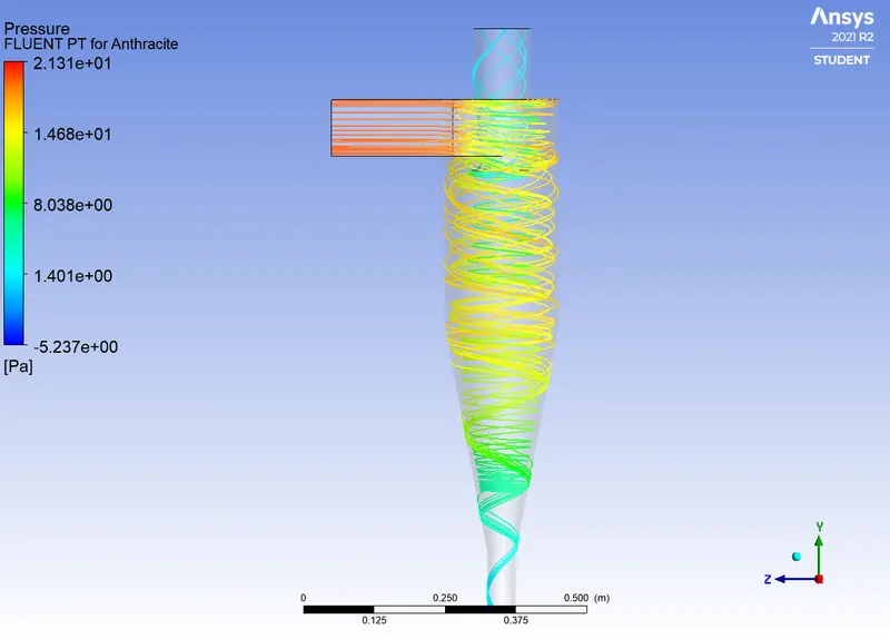
Number of particles tracked = 334
Number of particles escaped = 50
Number of particles trapped = 266
Number of incomplete particles = 18
Seperation efficiency = (266/334)*100 = 79.64 %
Case 1 - Particle size 5 micro metres
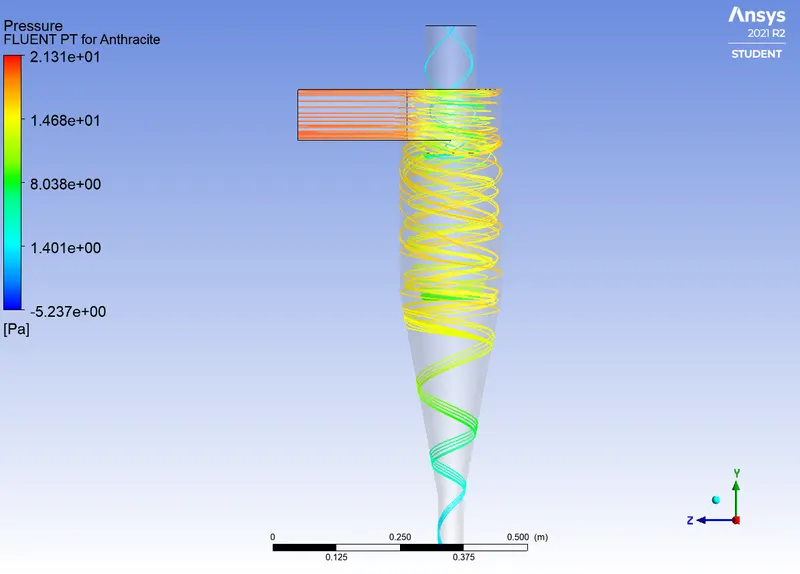
Number of particles tracked = 334
Number of particles escaped = 31
Number of particles trapped = 286
Number of incomplete particles = 17
Seperation efficiency = (286/334)*100 = 85.628 %
Case 2 - Velocity 1 m/s
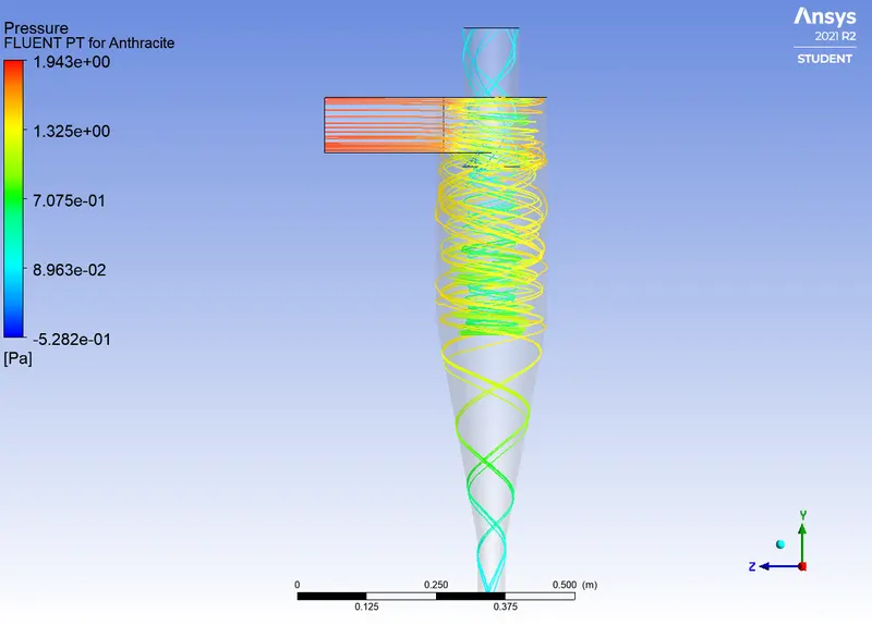
Number of particles tracked = 334
Number of particles escaped = 118
Number of particles trapped = 199
Number of incomplete particles = 17
Seperation efficiency = (199/334)*100 = 59.58 %
Case 2 - Velocity 2 m/s
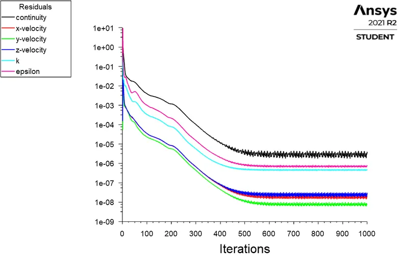
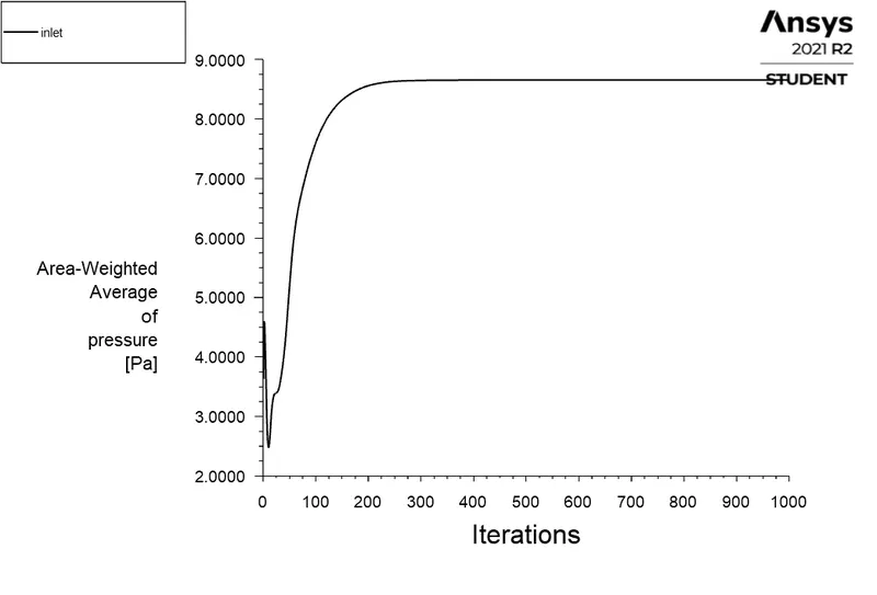
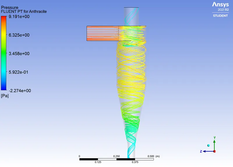
Number of particles tracked = 334
Number of particles escaped = 49
Number of particles trapped = 265
Number of incomplete particles = 20
Seperation efficiency = (265/334)*100 = 79.341 %
Case 2 - Velocity 3 m/s
Number of particles tracked = 334
Number of particles escaped = 31
Number of particles trapped = 286
Number of incomplete particles = 17
Seperation efficiency = (286/334)*100 = 85.628 %
Case 2 - Velocity 4 m/s
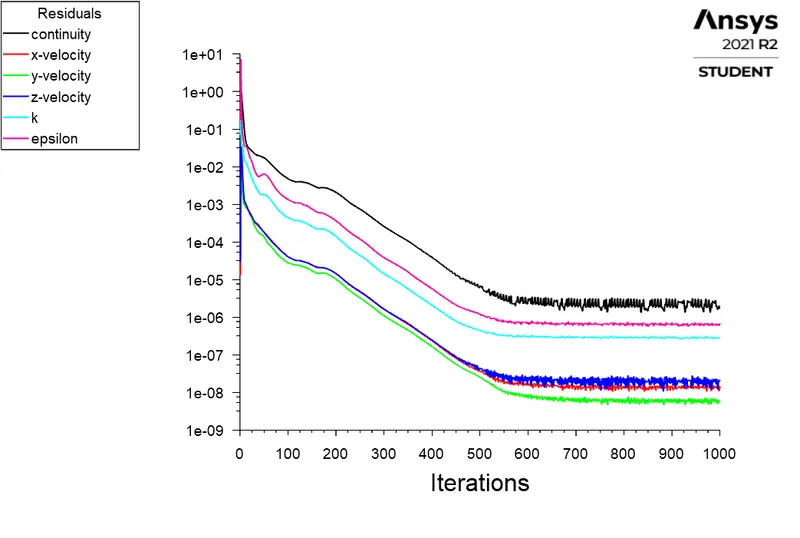
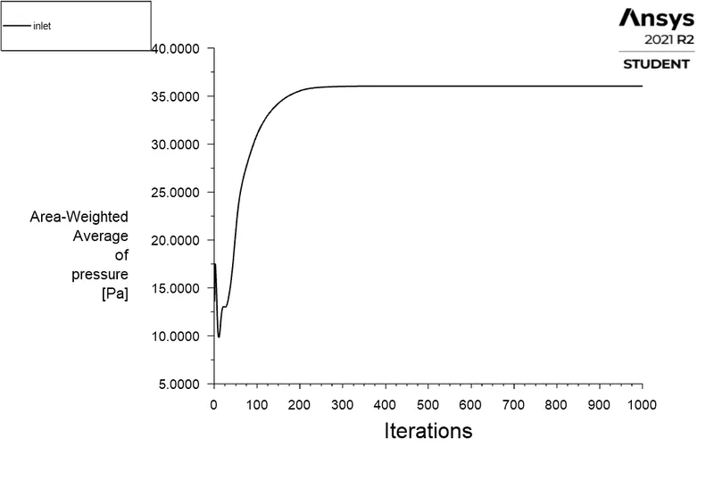
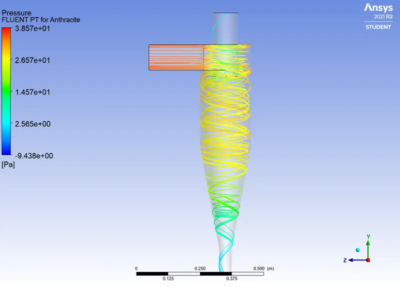
Number of particles tracked = 334
Number of particles escaped = 8
Number of particles trapped = 311
Number of incomplete particles = 15
Seperation efficiency = (311/334)*100 = 93.1137%
Case 2 - Velocity 5 m/s
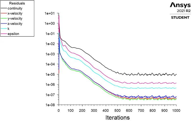
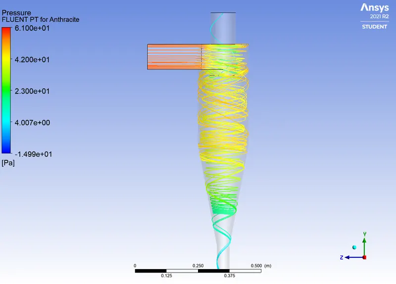
Number of particles tracked = 334
Number of particles escaped = 11
Number of particles trapped = 286
Number of incomplete particles = 37
Seperation efficiency = (286/334)*100 = 85.628%
Case 1
| Particle size(micro metres) | Tracked particles | Escaped Particles | Trapped particles | Incomplete particles | Seperator Efficiency (%) |
| 1 | 334 | 121 | 178 | 35 | 53.29 |
| 2 | 334 | 99 | 201 | 34 | 60.18 |
| 3 | 334 | 67 | 239 | 28 | 71.556 |
| 4 | 334 | 50 | 266 | 18 | 79.64 |
| 5 | 334 | 31 | 286 | 17 | 85.628 |
- From the above table we can conclude that the maximum seperating efficiency is shown when the particle size is of 5 micro metres
- It is also observed that when the particle size is increased we can trap more particles
- Also the number of incomplete particles is also lower when the particle size is increased
Case 2
| Velocity of particles and the fluid at Inlet (m/s) | Tracked particles | Escaped particles | Trapped particles | Incomplete particles | Seperator efficiency(%) |
| 1 | 334 | 118 | 199 | 17 | 59.58 |
| 2 | 334 | 49 | 265 | 20 | 79.341 |
| 3 | 334 | 31 | 286 | 17 | 85.628 |
| 4 | 334 | 8 | 311 | 15 | 93.1137 |
| 5 | 334 | 11 | 286 | 37 | 85.628 |
- A velocity of 4 m/s can be preffered for inlet fluid and particle velocity since it shows more efficiency for a 5 micro metre particle
- At a first glance the seperator efficiency seemed to be increasing with the increase in velocity but after a velocity of 4 m/s the efficiency seems decreasing
- Also less number of imcomplete particles occur at the same velocity (4 m/s)
Conclusions
- Explained the four emperical models to calculate the efficiency of a cyclone seperator
- Case 1 simulation was done where I changed the particle sizes from 1 to 5 micrometres with an Inlet velocity of 3m/s (also for particles)
- Case 2 simulation was done by changing the particle inlet and fluid inlet velocities from 1 to 5 m/s with a particle size of 5 micro metres
References