Week 8 Multi cell Battery Pack
Introduction :
Common to every battery system with series cells is the problem of cell imbalance. Cell balancing is a method of designing safer battery solutions that extends battery run time as well as battery life. The latest battery-protection and fuel-gauging ICs from.
What is cell imbalance?
If overheated or overcharged, Li-Ion cells are prone to accelerated cell degradation and can catch fire or even explode. Hardware and software protection is in place to mitigate these immediate dangers. In a multicell battery pack, which is commonly used in laptop computers and medical equipment, placing cells in series opens up the possibility of cell imbalance, a slower but persistent degradation of the battery.
No two cells are identical. There are always slight differences in the state of charge (SOC), self-discharge rate, capacity, impedance, and temperature characteristics, even for cells that are the same model from the same manufacturer and even from the same batch of production. When building multicell packs, manufacturers usually sort cells with similar SOCs by voltage. However, variations in an individual cell’s impedance, capacity, and self-discharge rate can still lead to a divergence in its voltage over time. Since most battery chargers detect full charge by checking whether the voltage of the entire string of cells has reached the voltage-regulation point, individual cell voltages can vary as long as they do not exceed the limits for overvoltage (OV) protection. However, weak cells—i.e., cells with lower capacity or higher internal impedance—tend to exhibit higher voltage than the rest of the series cells at full charge termination. These cells are weakened further by continuous overcharge cycles. The higher voltage of weak cells at charge completion causes accelerated capacity degradation.
On the other hand, in discharge, the weak cells tend to have lower voltage than the other cells, due to either higher internal resistance or the faster rate of discharge that results from their smaller capacity. This means that if any of the weak cells hits the cell undervoltage-protection limit while the pack voltage is still sufficient to power the system, the full capacity of the battery will not be used.
Cell-balancing techniques :
The impact of cell imbalance on run-time performance and battery life in applications using series-connected cells is certainly undesirable. The fundamental solution of cell balancing equalizes the voltage and SOC among the cells when they are at full charge. Cell balancing is usually categorized into two types—passive and active. The passive cell-balancing method, also known as “resistor bleeding balancing,” is simple and straightforward: Discharge the cells that need balancing through a dissipative bypass route. This bypass can be either integrated or external to the IC. Such an approach is favorable in low-cost system applications. The fact that 100% of the excess energy from a high energy cell is dissipated as heat makes the passive method less preferable to use during discharge because of the obvious impact on battery run time. Active cell balancing, which utilizes capacitive or inductive charge shuttling to transfer charge between battery cells, is significantly more efficient because energy is transferred to where it is needed instead of being bled off. Of course, the trade-off for this improved efficiency is the need for additional components at higher cost.
Passive cell balancing :
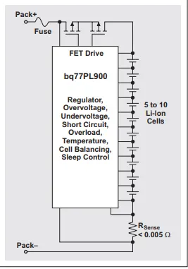
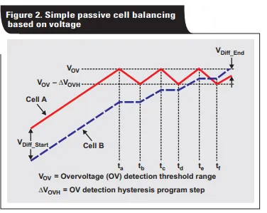
The easiest approach to cell balancing is to equalize cell voltages. For example, the bq77PL900, a battery-pack protector for 5 to 10 Li-Ion series cells, is used in cordless power tools, power-assisted bicycles and scooters, uninterruptible power supplies, and medical equipment. The bq77PL900 can act as a stand-alone battery-protection system (see Figure 1 ), comparing cell voltages with programmable thresholds to determine if cell balancing is needed. Figure 2 shows the operation principle. If any particular cell hits the threshold, charging is halted and an internal bypass is enabled. The charging is halted until the high-voltage cell hits the recovery limit, when the cell balancing will stop.
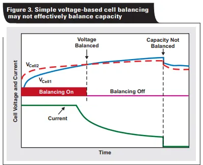
Cell-balancing algorithms that use only voltage divergence as a balancing criterion have the disadvantage of overbalancing or underbalancing because of the different impedance between cells (see Figure 3). The problem is that cell impedance also contributes to voltage divergence during charging. The pack protector using simple voltage based cell balancing cannot tell if the voltage difference is caused by the capacity or the impedance imbalance. Therefore, this type of balancing cannot guarantee that all cells will reach 100% capacity at full charge. The bq2084 is a fuel gauge with an improved version of voltage-based balancing. To minimize the effect of impedance differences between cells, the bq2084 balances only near the end of charge, where the current tapers off. In addition, the bq2084 is a more efficient implementation because it makes the balancing decision based on all cell voltages. Despite the improvements, this technique limits the balancing to high-SOC regions and can be performed only during charging.
Active cell balancing :
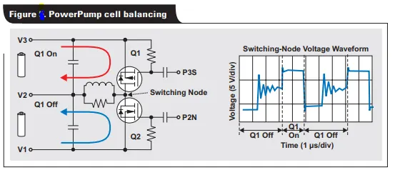
Active cell balancing overcomes the energy loss of the passive method by using capacitive or inductive charge storage and shuttling to deliver energy to where it is needed most, and with little loss. Thus it is preferable for efficiency-conscious designs and for applications where delivering maximum run time is top priority. The bq78PL114 PowerPump™ cell-balancing technology is TI’s latest implementation of active cell balancing using inductive charge transfer. PowerPump uses an n- and p-channel MOSFET pair and a power inductor to complete a charge-transfer circuit between an adjacent pair of cells. Shown in Figure 5, the MOSFETs and the power inductor form a buck/boost circuit. If the bq78PL114 determines that the top cell needs to transfer energy to the lower cell, the P3S signal, running at about 200 kHz with a duty cycle of 30%, triggers the energy to transfer from the top cell to the inductor through the top p-channel MOSFET, Q1. When the P3S signal resets, Q1 is turned off, and the energy stored in the inductor reaches a maximum.
Because the inductor current must flow continuously, the body diode of Q2 is forward-biased, completing the charge transfer from the inductor to the lower cell. In this process, energy is stored in the inductor with only minor loss due to the series resistance of the inductor and the ON resistance of the body diode. The bq78PL114 features three selectable balancing algorithms:
• Terminal-voltage pumping is just like the voltage based passive cell balancing described earlier.
• Open-circuit voltage (OCV) pumping compensates for impedance differences by estimating the OCV based on measurements of the pack current and cell impedance. •
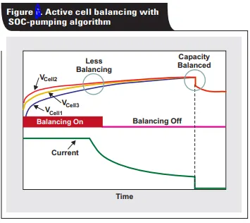
SOC pumping (predictive balancing) is like the bq20zxx family’s passive cell-balancing method based on SOC and capacity. The SOC-pumping algorithm determines the exact charge that needs to be transferred between cells so that cell capacities are balanced at the end of charge.This method therefore achieves the best active-balancing accuracy, as shown in Figure6.Because of the higher balancing current, PowerPump technology corrects cell imbalance much better than conventional integrated, passive balancing with internal bypass FETs. Adjustable by changing component values, the typical effective balancing current for a notebook PC is about 25 to 50 mA, which is about 12 to 20 times better than the internal IC bypass balancing. With this strength, most typical capacity imbalances (of less than 5%) can be overcome in one or two cycles. Apart from the obvious advantages, the beauty of the PowerPump cell-balancing technology is that balancing is achievable regardless of the individual cell voltages. Balancing can happen during any battery operation— charge, discharge, or rest—and even if the cell that provides the charge has a lower voltage than the cell that receives it! Compared with passive cell balancing, little energy is lost as heat.
Performance considerations for passive and active cell balancing :
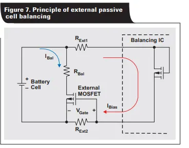
PowerPump cell balancing is fast by nature. A 2% capacity imbalance from a 2200-mAh cell can be balanced within a charge cycle or two. However, as previously mentioned, passive cell balancing using integrated FETs is limited by low balancing current and therefore may require multiple cycles to correct a typical imbalance. The balancing may even be overpowered by the rate of cell divergence/imbalance. To improve the speed of passive cell balancing, an external bypass can be established to utilize existing hardware. A typical implementation, shown in Figure 7, can be used with the bq77PL900, the bq2084, or the bq20zxx family. The internal balancing MOSFET for a particular cell is first turned on, creating a low-level bias current through the external filter resistors, RExt1 and RExt2, that connect the cell terminals to the IC. The gate-to-source voltage is thus established across RExt2, and the external MOSFET is turned on. The RDS(on) of the external MOSFET is negligible, and the external balancing current, IBal, is governed by cell voltage and RBal.
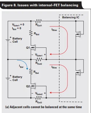
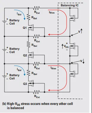
The drawback of this method is that balancing cannot be performed on adjacent cells at the same time (see Figure 8a). This is because, when adjacent internal FETs are turned on, there is no current flowing through RExt2, so Q1 remains off even when the internal switch is enabled. In practice, this is not an issue because the fast external cell balancing can quickly balance the cell associated with Q2, and then the cell associated with Q1 will be balanced. Another issue is the stress from the high drain-to-source voltage, VDS, that occurs when every other cell is balanced. In Figure 8b, the top and bottom cells are being balanced. Due to the cell-balancing bias, there is a high VDS at the middle internal switch that may exceed what the switch can sustain. The solution to this problem is to limit the maximum value of RExt or exclude simultaneous balancing of every other cell. Fast cell balancing is a new way of thinking about enhancing battery safety and performance. In passive balancing, the practical goal is to achieve capacity balance at the end of charge; but, due to the low balancing current, little can be done to also correct voltage imbalance at the end of discharge. In other words, overcharging weak cells can be avoided, but it may not be possible to improve battery run time because the extra energy is wasted in the bypass resistance as heat. With fast PowerPump active balancing, the two goals—achieving capacity balance at the end of charge, and minimizing voltage differences among cells at the end of discharge—can potentially be achieved at the same time. Energy is conserved and transferred to weaker cells, which increases discharge capacity.