Week 10 Thermal Management
why we need BTMS :
The main purpose of this master thesis is to develop a BTMS model for balancing the different cooling and heating circuits within the battery pack to fulfil the performance requirements.
Thermal Issues of Li-ion battery :
Lithium-ion cells performance depends on both the temperature and the operating voltage. Lithium-Ion cells work well when cells operate within limited voltage and temperature. Otherwise, damage will occur to the cells and will be irreversible.
In over-voltage situations the charging voltage exceeds the bearable cell voltage, resulting in excessive current flows and at the same time, it causes two problems.
At excessive currents the Lithium-ions are deposited more rapidly than intercalation to the anode layers, Lithium ions are then deposited on the surface of the anode as metallic Lithium. This is Lithium plating. It gives rise to the reduction in the free Lithium ions and an irreversible capacity loss. There are two types of metal lithium plating, namely homogeneous lithium plating and heterogeneous lithium plating, but the lithium plating is dendritic in form. Eventually it can result in a shortcircuit between the electrodes.
High temperature increases the reaction rate with higher power output, however, it also increases the heat dissipation and generates even higher temperatures. Unless heat is dissipated quicker than heat is generated, the temperature will be higher and finally a thermal runaway will result.
Thermal runaway consists of several stages and each stage will give rise to more irreversible damage to cells. First, the SEI layer is dissolved to electrolyte at round 80ºC. The primary overheating may result from excessive current or high ambient temperature. After breakdown of the SEI layer, electrolyte begins to react with the
anode. This reaction is exo-thermal which drives the temperature higher. Secondly, the higher temperature causes the organic solvents to break down with the release of hydrocarbon gases. Normally this starts at around 110 ºC. The pressure inside cells is built up by the gas and the temperature is beyond the flashpoint. However, the gas does not burn due to the lack of oxygen. A vent is needed to release the gas in order to keep cells under proper pressure and avoid a possible rupture. Then, the separator is melted and short-circuits occur between the anode and cathode at 135 ºC. Finally, the metaloxide cathode breaks down at 200 ºC and releases oxygen which allows the electrolyte and hydrogen gas to burn. This reaction is also exo-thermal and drives temperature and
pressure still further.
In addition, uneven temperature distribution is another problem of batteries. Typically, it is caused by the excessive local temperature, variable current in a cell and the thermal conductivity of the case, as well as the placement of positive and negative terminals and so on. It results in local deterioration and even thermal runaway with reducing the battery lifetime.
Operating Requirments :
The battery temperature should be controlled within temperature limits to avoid the thermal issues and improve the performance. The temperature range affects the battery power and battery cycle life, see Figure 2.2 and Figure 2.3. At the same time, the temperature distribution should be even to guarantee the battery performance and lifetime. That is also the reason why the battery thermal management system is necessary to the battery system.
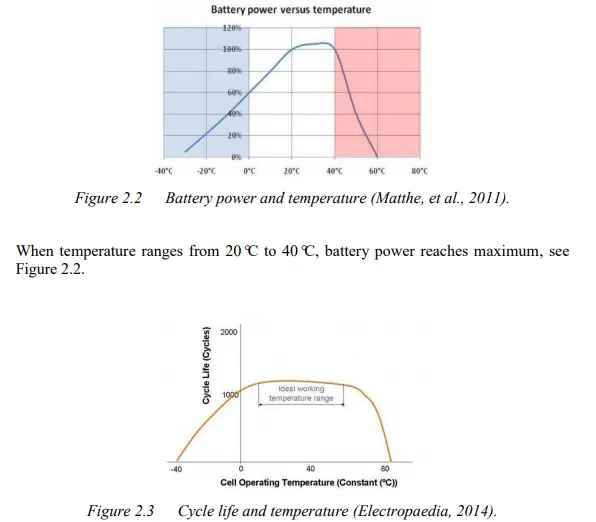
The cycle life goes down slowly below 10°C because of anode plating and drops off quickly above 60°C due to the breakdown of electrode materials, see Figure 2.3. Generally, the temperature must be controlled between 20°C and 40°C to ensure the performance and cycle life. Moreover, the temperature distribution is controlled under 5K to keep the safety and lifetime of battery (Pesaran, 2002). In addition, ventilation is also essential to the battery system and should be taken into account.
Battery Thermal Management Systems (BTMS) :
The battery pack for safety, performance (both power and capacity) and lifespan reasons should be stored in a controlled surrounding where the temperature is controlled and there is no risk of thermal runaway. According to a foundational research (Pesaran, 2001), the BTMS should be equipped with four essential functions to ensure the right operation conditions of the battery pack.
- Cooling: Due to inefficiency, battery cells will not only generate electricity but also heat. This heat should be moved from the battery pack when battery temperature reaches the optimum temperature or even in advance. Thus, a cooling function is required in BTMS.
- Heating: In cold climates, battery pack temperature probably falls below the lower temperature limit. Hence, a heating function, such as PTC heater, is required to assist the battery pack to reach the proper temperature range in a shorter time.
- Insulation: In extreme cold or hot weather, the temperature difference between the inside and outside of the battery pack is much larger than that in mild weather. Battery temperature will thus fall (cold) or rise (hot) sooner out of the proper temperature range. To prevent this, good insulation can slow down the falling or rising of battery temperature, especially when the vehicle is parked outdoors.
- Ventilation: Ventilation is required to exhaust the hazardous gases within battery pack. In some systems, such as air systems, this function is combined with cooling and heating functions.
Technologies of BTMS :
a)Air Cooling and Heating:
Air systems use air as the thermal medium. The intake air could be direct either from atmosphere or from the cabin and could also be conditioned air after a heater or evaporator of an air conditioner. The former is called passive air system and the latter is active air system. Active systems can offer additional cooling or heating power. A passive system can offer some hundreds of watts cooling or heating power and an active system power is limited to 1 kW. (Valeo, 2010) Because in both cases the air is supplied by a blower, they are also called forced air systems. The following figure shows a schematic description of systems.
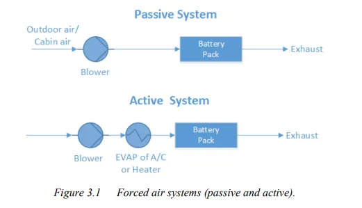
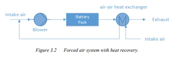
Note that the air system offers full functions of heating, cooling and ventilation. There is no need to build an additional ventilator, but it must be noted that the exhaust air cannot be returned to the cabin again. In some cases, a heat recovery unit (air-air heat exchanger) is mounted after the battery pack in order to recovery the heat from the exhaust air. It can prevent mixture of exhaust air with intake air and at the same time provide an extra saving potential. The forced air system with heat recovery is presented below .
Liquid Cooling and Heating :Besides air, liquid is another heat transfer fluid to transfer heat. There are generally two groups of liquids applied for thermal management systems. One is dielectric liquid (direct-contact liquid) which can contact the battery cells directly, such as mineral oil. The other is conducting liquid (indirect-contact liquid) which can only contact the battery cells indirectly, such as a mixture of ethylene glycol and water. Depending on the different liquids, different layouts are designed. For direct-contact liquid, the normal layout is to submerge modules in mineral oil. For indirect-contact liquid, a possible layout can be either a jacket around the battery module, discrete tubing around each module, placing the battery modules on cooling/heating plate or combining the battery module with cooling/heating fins and plates. (Pesaran, 2001) Between these two groups, indirect contact systems are preferred in order to achieve better isolation between battery module and surroundings and thus better safety performance.
By different heat-sinks for cooling, liquid systems can also be categorized into either passive systems or active systems. In passive liquid system, the heat-sink for cooling is a radiator. This system has no ability to heat. Figure 3.3 presents the systematic scheme of a passive liquid system. Heat transfer fluid is circulated by the pump within a closed system. The circulating fluid absorbs heat from battery pack and releases heat via a radiator. The cooling power depends strongly on the temperature between ambient air and battery. Fans behind the radiator can improve the cooling performance, but if ambient air is higher than the battery temperature or the difference between them is too small, the passive liquid system becomes ineffective.
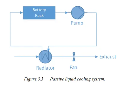
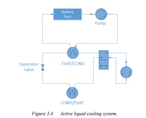
Figure 3.4 shows the systematic scheme of an active liquid system. There are two loops. The upper is called the primary loop and the lower the secondary loop. The primary loop is similar to the loop in a passive liquid system, where the heat transfer fluid is circulated by pump. The secondary loop is actually an air conditioning loop (A/C loop). The upper heat exchanger instead of being a radiator works as an evaporator (EVAP) for cooling operation and connects both loops. During heating operation, the 4 way valve will be switched, and the upper heat exchanger works as a condenser (COND) and the lower heat exchanger works as an evaporator. The heating operation loop is also called heat pump loop.
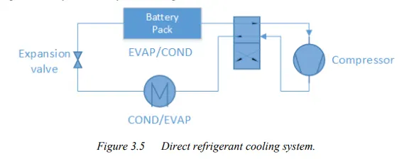
Direct Refrigerant Cooling and Heating :Similar to active liquid systems, a direct refrigerant system (DRS) consists of an A/C loop, but DRS uses refrigerant directly as heat transfer fluid circulating through battery pack. The systematic layout is in Figure 3.5.
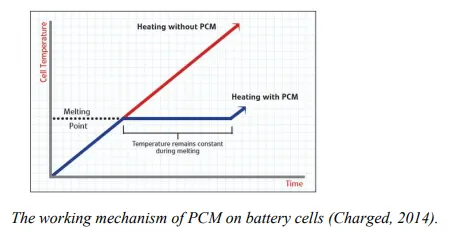
PCM: During melting, heat is absorbed by PCM and is stored as latent heat until the latent heat is up to the maximum. The temperature is kept at melting point for a period and the temperature increase is delayed. Therefore, PCM is used as conductor and buffer in battery thermal management systems. Figure 3.6 shows the working mechanism of PCM on battery cells. Also, a PCM is always combined with air cooling system or liquid cooling system to manage the battery temperature.
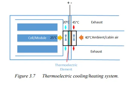
Thermo-electric Module: To improve cooling/heating power of passive air systems, there are two possible upgrades. One is through thermo-electric modules, which will be introduced here. The other is a heat pipe will be discussed in Section 3.2.6. Thermo-electric module can convert electric voltage to temperature difference and viceversa. Here the former effect is adopted. That means it transfers heat through the module by consuming electricity directly. The schematic structure is presented in Figure 3.7. Two fans are installed to improve heat transfer by forced convection. To combine a passive air system with thermo-electric module, the combined system is able to cool down the battery even lower than the intake air temperature, but the power is still limited to around some hundreds of watts and less than one kW. (Valeo, 2010) It’s easy to switch between cooling and heating operation. To achieve that, the poles of electrodes need to be reversed.
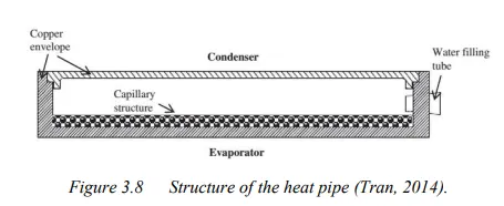
Heat Pipe: Besides thermo-electric modules, a heat pipe is another way to upgrade passive air systems. The structure of a heat pipe is shown in Figure 3.8. The flat copper envelope of the heat pipe was under partial vacuum. The capillary structure is made of sintered copper powder. The heat pipe uses water as the working fluid. Water on the evaporator side will absorb heat and become vapour lower 100°C due to low pressure inside. Water on the condenser will dissipate heat to the surrounding and become liquid again. This cycle repeats again and again.
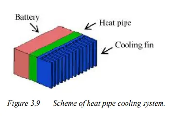
The following figure shows the schematic description of a heat pipe cooling system. A battery as heat source sits below the heat pipe (on the evaporating side). Cooling fins as heat sinks are on the heat pipe (on the condensing side). According to the conclusion of an experiment (Tran, 2014), heat pipe cooling system can reduce the thermal resistance by 30% under natural convection as compared to without heat pipe . A thermal resistance reduction of 20% under low air velocity convection is possible. Note that, in comparsion to thermo-electric, a heat pipe is more reliable, because there are no moving parts and no energy consumption. However, a heat pipe is unable to heat the battery due to its fixed structural layout.
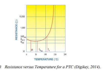
PTC Heater :PTC thermistors have many self-heated applications by utilizing their own voltagecurrent or current-time characteristics. One of the applications is as a self-regulating heater known as a PTC heater. The temperature of a PTC heater can be kept at a fixed point through adjusting the resistance of PTC heater automatically, see Figure 3.10.
Evaluation of Different Technologies :
Here the comparison of different battery thermal management systems has been made according to several item..
Forced-Air System :
Forced-air cooling system with a simple structure has the advantage of high reliability and low cost as well as easy maintenance, while it has poor thermal management, i.e. beyond operating temperature, uneven uniformity of temperature distribution and spread of thermal runaway.
In high ambient temperatures e.g. 45°C-50°C, the temperature inside the battery pack exceeds 55°C which is beyond the operating temperature and will result in thermal runaway. The uniformity of temperature distribution is also crucial due to the effect of degradation and cycle life. If one ignores the ambient temperature, the difference between cells is 2°C at the discharge current 2C-rate, and 4.8°C at the discharge current 6.67C-rate. The uniformity of temperature distribution is also affected by the flow rate. As the flow rate increase, cell maximum temperature difference will increase, e.g. 3K at Re=136 and 4.8K at Re=1347. With the increasing flow rate, the cell maximum temperature difference can be even over 5K. (Sabbah, et al., 2008) It will give rise to degradation and the decrease of cycle life because the heat transfer between cells is quicker than the heat transfer from battery pack to air. So if one cell fails, thermal runaway will spread over the battery pack. .
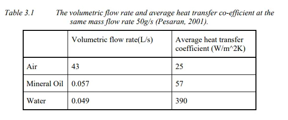
The following Table 3.1 shows that at the same flow rate the air volume is much bigger than the water volume, while the air heat transfer co-efficient is much lower than water heat co-efficient. So for air cooling to dissipate heat as much as water cooling, it requires higher volumetric flow rate which means more space and more power. Air cooling system takes up larger space and consumes much more energy comparing to liquid cooling system.
Liquid System:
There are three types of cooling systems, namely passive cooling system, active cooling system, and refrigerant cooling system.
The passive cooling system is affected by the ambient temperature, because the heat dissipation is dependent on the radiator and the radiator dissipates heat through the temperature difference between liquid and the ambient temperature. Under normal circumstances, it works well, but under high ambient temperature it is insufficient.
Active cooling systems have good thermal performance which can keep the battery pack within the operating temperature and keep temperature distribution between cells even because of high heat co-efficient of the coolant. Due to many auxiliaries and moving parts, the structure is complicated and difficult to maintain. It also has the tendency of leaking out.
Compared to active cooling systems, direct refrigerant cooling systems are more efficient because they use refrigerant directly to cool the system instead of using refrigerant to cool coolant first and then using coolant to cool the system. The weaknesses of refrigerant cooling system are complicated structure and difficult maintenance, as well as potential to leak out and so on.
PCM System
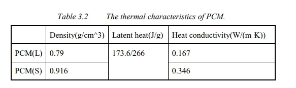
:PCM cooling systems perform well on thermal management. Even under high ambient temperatures from 45°C to 50°C, the temperature inside the cell pack is always below 55°C because of high thermal conductivity and latent heat. (Sabbah, et al., 2008) Table 3.2 shows the characteristics of PCMs. In the case of stressful situations e.g. at current discharge rate 6.67C-rate and ambient temperatures of 45°C, the cell maximum temperature difference doesn’t exceed 0.5K. And at normal conditions the difference of temperature between cells is negligible. (Sabbah, et al., 2008) If one cell fails, thermal runaway will not propagate because the PCM-graphite matrix absorbs and spreads the heat quickly.
The weakness of PCM is that it is more suitable for cold conditions or in space. When the temperature of the battery pack is higher than the temperature of the PCM melting point, heat is stored as latent heat and will be released to the module of battery when the ambient temperature is lower than the temperature of the PCM melting point. The structure of PCM without new components is simple, light and space-saving. But it still has the potential of flammability and electrical conductivity as well as volume change due to the characteristic of the PCM-graphite.
THERMO Electrics :
Thermo-electrics have small and lightweight structures and can turn a heating element to an efficient cooling element by reversing the polarity. Without moving parts to wear, thermo-electrics are reliable, durable and of low maintenance. And also easy to replace in case of failure. In addition, operation is quiet and vibration-free.
The weakness of thermo-electrics is low efficiency. The highest efficiency is up to 0.8 which means more power is needed than heat dissipated. (Huairui, 2014)The performance is associated with the required temperature difference. The greater the temperature difference is, the lower the pumping capacity is, until it stops working at 70K. So under high temperature the temperature difference is great and thermo-electrics perform badly. And there is one technical problem not solved: that the hot and cold sides are close to each other.
Recommended Cooling System :
Through the trade-off of the items mentioned above, two cooling systems are recommended, the performance of the items is described as a score and the importance of the items is described as a weighting factor. The product of score and weighting factor is the total score of the system,. The systems of the two highest scores are the recommended systems.
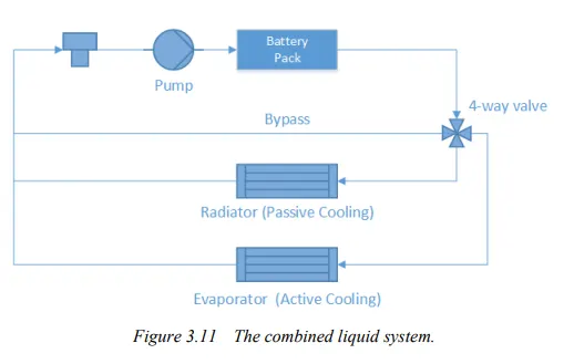
Combined Liquid System (CLS): The first is the liquid cooling system, which has four working modes: bypass with heater working; bypass without heater working; passive cooling system; and active cooling system (see Figure 3.11). The cooling system takes advantage of both passive cooling system and active cooling system. Passive cooling system has simple structure and is able to dissipate heat under normal conditions with low energy consumption. Under extreme condition, active cooling system has good thermal performance to keep battery temperature in the required range.
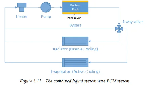
PCM Model (CLS+PCM): The other preferred system is the combination of PCM material and CLS. PCM layers are inserted into battery pack. It uses the advantage of PCM to have good thermal performance, and CLS compensates for the limited operating temperature of PCM, see Figure 3.12.